Page is loading ...

HA028908U180
Issue 3 Jly 10
HA028908U180
Issue 3 Jly 10
180 mm PAPERLESS GRAPHICS RECORDER: CIRCUIT BOARD RETROFIT INSTRUCTIONS 180 mm PAPERLESS GRAPHICS RECORDER: CIRCUIT BOARD RETROFIT INSTRUCTIONS
Circuit board retrofit instructions
180 mm Paperless graphic recorders
INTRODUCTION
These instructions are intended to help service engineers and others to add or replace 180
mm recorder circuit boards. The instructions apply to the power supply unit, as well as to
input boards and option boards, including serial comms. and USB options For all other
replacement and or retrofit instructions, including the main (micro) board and the display
inverter board, refer to HA028909U180.
WARNING!
Isolate the recorder from all hazardous voltage sources, both supply and signal.
Allow the recorder to cool for at least 10 minutes after powering off .
CAUTION
These procedures involve the handling of components which are sensitive to
static electrical discharge. All relevant personnel must be aware of static han-
dling procedures.
Note: The illustrations in this document show the addition of an eighth input
board, and the ninth option board to a recorder already fitted with seven input
boards and eight option boards. The procedure for fitting other boards is simi-
lar, the difference being in the organisation of the flexi-cable chain, and in the
setting of the switches and links which define board number.
BOARD LOCATION RULES
1. If Relay output boards are fitted, they must be located in the lowest numbered slots.
2. Relay board types must be fitted in the order: Change-over, Normally-closed; Nor-
mally-open.
3. If Event input boards are fitted, they must be fitted in the lowest numbered slots
which are available after all relay boards have been fitted.
4. If analogue output boards are fitted, they must be fitted in the lowest numbered
slots which are available after all relay and Event input boards have been fitted.
Specification subject to change without notice. ©Eurotherm Limited.
EUROTHERM LIMITED
Faraday Close, Durrington, Worthing, West Sussex, BN13 3PL
Telephone: +44 (0)1903 268500 Facsimile: +44 (0)1903 265982
e-mail: info.uk@eurotherm.com
Website: http://www.eurotherm.co.uk
HA028908U180/3 (CN26514)
Page 1

HA028908U180
Issue 3 Jly 10
HA028908U180
Issue 3 Jly 10
180 mm PAPERLESS GRAPHICS RECORDER: CIRCUIT BOARD RETROFIT INSTRUCTIONS 180 mm PAPERLESS GRAPHICS RECORDER: CIRCUIT BOARD RETROFIT INSTRUCTIONS
Page 19Page 2
18
USB OPTION RETROFIT
Following on from instruction 17:
If this is the first time a USB option has been fitted, peel off the self-
adhesive label ('e') covering the apertures, for the USB connectors,
in the rear panel.
If not already fitted, insert two plastic stand-off pillars ('b') to the
Battery/Ethernet/Serial comms board.
Fit the USB board onto the stand-off pillars, ensuring that the con-
nectors face the rear panel.
Secure the USB board using the four screws ('f') and sprung wash-
ers.
Connect the USB harness.
Re-assemble the recorder.
19
e
f
FLEXI CABLE ORGANISATION

HA028908U180
Issue 3 Jly 10
HA028908U180
Issue 3 Jly 10
180 mm PAPERLESS GRAPHICS RECORDER: CIRCUIT BOARD RETROFIT INSTRUCTIONS 180 mm PAPERLESS GRAPHICS RECORDER: CIRCUIT BOARD RETROFIT INSTRUCTIONS
d
Page 3Page 18
RELAY / EVENT INPUT BOARD SWITCH SETTINGS
Before fitting relay or event input boards, the two elements of
the switch located near the front edge of the board must be
set to define its board number. The figure below, and the ac-
companying tables give details. (Figure shows the relay board
- the event input board is similar).
INPUT BOARD LINK SETTINGS
Before fitting an input board, it is necessary to set the board address. The address is set by
positioning links, as shown below.
ANALOGUE OUTPUT BOARD LINK SETTINGS
Before fitting an analogue output board, it is necessary to set the board address according
to which output board it is. The address is set by positioning links, as shown below.
17
SERIAL COMMUNICATIONS RETROFIT
If a USB board is fitted, remove it by:
a. Unclipping the loom and disconnecting it from the micro board.
b. Removing the four securing screws ('a') and associated spring wash-
ers.
c. Compressing the top of the stand-off pillars ('b'), whilst easing the
USB board up and away.
a
a
b
b
c
c
Place the board and associated loom/harness in a
static safe area.
Disconnect the battery loom, and remove the bat-
tery.
Undo the two screws ('c') securing the Battery/Eth-
ernet board to the chassis, and remove the board.
Lever out the blanking panels, filling the 9-way D-
type apertures, in the same way as is described for
22-way connectors on page 4.
If a USB option is to be fitted, insert the two plastic standoff pillars ('b') into the new Serial
communications board.
Slide the new board into the card cage, and secure it using the four hex jacking screws (d)
and associated shake-proof washers, and the two screws 'c' previously removed. Fit either
the battery previously removed, or a new battery.
Connect the serial communications flexi cable and the
battery board harness to the serial communications
board. Clip to the circuit board retainer as shown.
If the USB option is to be fitted, see instruction 19,
otherwise, re-assemble the recorder.

HA028908U180
Issue 3 Jly 10
HA028908U180
Issue 3 Jly 10
180 mm PAPERLESS GRAPHICS RECORDER: CIRCUIT BOARD RETROFIT INSTRUCTIONS 180 mm PAPERLESS GRAPHICS RECORDER: CIRCUIT BOARD RETROFIT INSTRUCTIONS
Page 4
POLARISING PLUGS
In order to avoid accidental insertion of an incorrect board type, it is recommended that a
polarising plug be inserted into the board side of the connector in the locations indicated
in the table. Failure to do so may damage the recorder. As shown in the figure, the plug is
inserted into the connector and the 'handle' is then snapped off.
Notes:
1. All relay board types have the same polarising key position
2. Input boards do not require polarising plugs.
NC CNONCCNO NC CNO NC CNONCCNO NC CNO
V+ V- I V+ V- IV+V-I V+ V- IV+V-IV+ V- I
123456C 123456C
Reserved
Reserved
CNCCNC CNCCNC CNCCNC CNCCNC
CNOCNO CNOCNO CNOCNO CNOCNO
V+
-
I+ V+
-
I+V+
-
I+ V+
-
I+
CONNECTOR LABELS
A set of self-adhesive labels (depicted below) is supplied, for the user to apply to the connec-
tor.
Page 17
CJ Sensor cover
(for input boards only)
Fit EMC springs as
required and secure
with plastic rivets.
Remove both blanking panels
a
b
c
Fit polarising plug, then push
connector into slot
CONNECTOR FITTING
EMC springs must be fitted as shown.
Option boards require one EMC spring, fitted at the appropriate end of the connector slot.
Input boards require two EMC springs to be fitted, one at each end of the connector.
SERIAL COMMUNICATIONS AND USB OPTIONS
All recorders are fitted as standard with the 'Battery/Ethernet' board. To fit Serial communi-
cations, this Battery/Ethernet board is replaced by a similar board, which contains not only
the battery and RJ45 Ethernet connector, but also all the necessary components and con-
nectors for serial communications.
The USB option (if fitted) is mounted on plastic standoff pillars attached to the Battery/Eth-
ernet board.
The following procedure assumes a USB option board is fitted, but the Serial communica-
tions option is not fitted. Should this not be the case, the user should ignore any irrelevant
instructions.
With the recorder removed from the panel and isolated from supply power, remove the re-
corder top plate, by removing the four Torx-headed screws 'A' (two each side) and the pan-
head pozidriv screw 'B' at the rear, then lifting the cover up and out from under the gasket
'C'.
A
A
A
B
A
C
17
It is possible to carry out this procedure without
removing the card cage
For easier access, the card cage may be removed
by undoing the four screws 'L' which secure the
card cage to the chassis and then rotating and lift-
ing the card cage out of the chassis, disconnecting
all the relevant connectors as they become acces-
sible.
L
L
L
L
Note: It will be necessary to reset the time and date if the battery is disconnected.

HA028908U180
Issue 3 Jly 10
HA028908U180
Issue 3 Jly 10
180 mm PAPERLESS GRAPHICS RECORDER: CIRCUIT BOARD RETROFIT INSTRUCTIONS 180 mm PAPERLESS GRAPHICS RECORDER: CIRCUIT BOARD RETROFIT INSTRUCTIONS
Page 5Page 16
PSU REPLACEMENT
If the PSU is not to be replaced, please ignore this section, and start at instruction 7 instead.
With the recorder removed from the panel and isolated from supply power, remove
the recorder top plate, by removing the four Torx-headed screws 'A' (two each side)
and the pan-head pozidriv screw 'B' at the rear, then lifting the cover up and out from
under the gasket 'C'.
Avoiding any hot components, carefully discon-
nect all the Power Supply Board connectors (D). (If
the loom from the PSU to the micro board is to be
replaced, this can be done now, remembering to se-
cure the replacement using the clips 'F').
The PSU may be removed by undoing the four secur-
ing screws 'E'.
If the replacement PSU is of the same type as the
existing one (i.e. the supply voltage is not being
changed), the new PSU board can now be fitted, and
secured using screws E, previously removed.
Reconnect all the connectors ('D') previously re-
moved.
1
2
A
A
A
B
A
C
D
E
E
E
E
D
F
3
PSU
AUTOCONFIGURE ACCESS
Instrument
Groups
Channels
Views
Archive
Events
Event Buttons
Messages
User Linearisations
Batch
Maths
Totalisers
Counters
Timers
Connections
Master Comms
Output channels
Demand Writes
Emails
Reports
Options
Archive
System
Save/R..
Config
Security
Network
Trial Mode Disabled
Trial Time Remaining 30 day(s)
Fitted channels 6
Virtual channels 36
Maths 18
Totalisers 12
Counters 6
Groups 12
Batch Enabled
Security Manager Disabled
Auditor 21CFR11
Screen Builder Full
Bridge Level Full
Master Comms Devices 16
Relay Boards 2
Relays on Board 1 3
Relays on Board 2 4
Event Input Boards 1
Analogue Output Boards 1
(currently 1)
(currently 0)
(currently 0)
Apply Discard
Autoconfigure
Root Menu
Key
Root Menu
Home Operator
File
Cycle Goto Group
Remove Media
Note: Actual display depends on which op-
tions are fitted.
If the replacement PSU is of a different type (e.g. low voltage instead of standard), continue
at instruction 4.
If input or option boards are to be replaced, or retro-fitted, please continue at instruction 8.
If not, replace the recorder top and secure it using the 5 screws ('A' and 'B') previously re-
moved.

HA028908U180
Issue 3 Jly 10
HA028908U180
Issue 3 Jly 10
180 mm PAPERLESS GRAPHICS RECORDER: CIRCUIT BOARD RETROFIT INSTRUCTIONS 180 mm PAPERLESS GRAPHICS RECORDER: CIRCUIT BOARD RETROFIT INSTRUCTIONS
Page 15Page 6
Remove the power cord connector from the rear panel connector. Remove the existing
PSU as described in instruction 2, above and fit the replacement physically, but without
connecting it up.
SUPPLY VOLTAGE CHANGE
Two versions of the power supply unit (PSU) are available, viz, Standard and Low Voltage.
The standard unit accepts supplies of 85 to 265 Volts, 47 to 63 Hz ac, and 110 to 370Volts
dc. The low voltage unit accepts ac supplies of 20 to 42Volts, 45 to 400 Hz, and dc supplies
of 20 to 54 Volts.
When changing PSU versions, the existing supply voltage connector must be replaced with
one suited to the supply voltage. This procedure is detailed below, for changing from the
standard version to the low voltage version. The description should also be adequate for
the situation where it is required, instead, to change from the low voltage version to the
standard version.
If necessary remove the connectors (D) from the PSU.
Remove the old power harness by pulling off the push-
on connectors on the back of the IEC plug ('G') and of
the copper, 'U' shaped, bonding earth connection (H).
The IEC (mains) plug can now be removed from the
rear panel, by pressing on the securing 'clips' or latch-
es, on the top and on the underside of the connector.
Pass the rectangular connector and associ-
ated power leads through the support plate,
then through the aperture in the rear panel
and finally, through the backing plate. Se-
cure the assembly with screws J.
Make the earth connections, and connect the
power leads to the PSU.
Fit a new Supply Voltage label.
See 'Wiringdetails' on page 14 for dc wiring
details.
If input or option boards are to be replaced, or retro-fitted, please continue at instruction
8. If not, replace the recorder top and secure it using the 5 screws ('A' and 'B') previously
removed.
Support plate
Backing plate
J
4
D
G
H
5
6
12345678910111213141516171819202122
Relay 1
nc cno
Relay 2
nc cno
Relay 3
nc cno
Relay 1
nc cno
Relay 2
nc cno
Relay 3
nc cno
c
nc
no
Contacts shown in �
power off/alarm state
Three changeover relays
12345678910111213141516171819202122
Rly 1
cc
Rly 2
nc c
Rly 3
nc cncnc
Rly 4
c
nc
Contacts shown in �
power off/alarm state
Four normally closed relays
Rly 1
cc
Rly 2
nc c
Rly 3
nc cncnc
Rly 4
12345678910111213141516171819202122
Rly 1
cc
Rly 2
no c
Rly 3
no cnono
Rly 4
Four normally open relays
Rly 1
cc
Rly 2
no c
Rly 3
nocnono
Rly 4
c
no
Contacts shown in �
power off/alarm state
Relay outputs
12345678910111213141516171819202122
123 456C123456C
Event inputs (max 4 option boards)
Event input Number
C123456
+2 to +30 V
+0.8 to -30 V
User 0V
Input 6 shown; �
inputs 1 to 5 identical
Event input Number
C123456
Voltage inputsContact closure inputs
Behaviour undefined for
+0.8 < Vin < +2 V
Voltage
outputs
+-
V+
I+
+-
Current
outputs
V+
I+
12345678910111213141516171819202122
V+ I+ V+ I+ V+ I+ V+ I+
Channel
1
Channel
2
Channel
1
Channel
2
Analogue outputs (max 4 option boards)
12345678910111213141516171819202122
V+ V-
I
V+ V-
I
V+ V-
I
V+ V-
I
V+ V-
I
V+ V-
I
Channels �
1, 7, 13, 19, �
25, 31, 37, 43
Analogue inputs
Channels �
2, 8, 14, 20, �
26, 32, 38, 44
Channels �
3, 9, 15, 21, �
27, 33, 39, 45
Channels �
4, 10, 16, 22, �
28, 34, 40, 46
Channels �
5, 11, 17, 23, �
29, 35, 41, 47
Channels �
6, 12, 18, 24, �
30, 36, 42, 48
WIRING DETAILS
Pinouts

HA028908U180
Issue 3 Jly 10
HA028908U180
Issue 3 Jly 10
180 mm PAPERLESS GRAPHICS RECORDER: CIRCUIT BOARD RETROFIT INSTRUCTIONS 180 mm PAPERLESS GRAPHICS RECORDER: CIRCUIT BOARD RETROFIT INSTRUCTIONS
I/O3
I/O1
I/O
2
I/O0
Page 7Page 14
If necessary, remove the rear terminal cover, by
undoing the (captive) securing screw 'K'.
Undo the four screws 'L' which secure the card
cage to the chassis.
Rotate and lift the card cage out of the chassis,
disconnecting all the relevant connectors as they
become accessible.
With the recorder removed from the panel and isolated from supply power, remove
the recorder top plate, by removing the four Torx-headed screws 'A' (two each side)
and the pan-head pozidriv screw 'B' at the rear, then lifting the cover up and out from
under the gasket 'C'.
7
A
A
A
B
A
C
L
L
L
L
K
8
Micro board
9
Unclip the power loom , battery loom and (if fitted) the serial
comms and USB looms. Remove the circuit board retainer
by removing the plastic rivets 'M', undoing the two securing
screws 'N', and carefully lifting it away from the card cage,
ensuring that no damage is done to the various flexies.
M
M
WIRING DETAILS
Connector locations
Input channels 1 to 7
Input channels 1 to 6
Input channels 7 to 12
Input channels 1 to 7
Input channels 13 to 18
Input channels 19 to 24
Input channels 1 to 7
Input channels 25 to 30
Input channels 31 to 36
Input channels 1 to 7
Input channels 37 to 42
Input channels 43 to 48
Option board 3 Option board 4
Option board 1 Option board 2
Not used Option board 9
Option board 7 Option board 8
Option board 5 Option board 6
Serial comms (option)
L
N
E
Mains (supply)
connection
USB Ports (option)
Ethernet
RJ45
USB1 USB2
Port 1
Port 2
Safety Earth
(M4)
Supply power connection for dc supplies
N
N

HA028908U180
Issue 3 Jly 10
HA028908U180
Issue 3 Jly 10
180 mm PAPERLESS GRAPHICS RECORDER: CIRCUIT BOARD RETROFIT INSTRUCTIONS 180 mm PAPERLESS GRAPHICS RECORDER: CIRCUIT BOARD RETROFIT INSTRUCTIONS
Page 13Page 8
Before fitting a new input board, a link must be set to define the board number. Although
there can be up to eight input boards fitted, there are only two per I/O port on the micro-
board. It is thus necessary only to define the board as board 1 or board 2, as shown on
page 3 of this document. The figure below shows the slot numbers for all possible input
and option boards.
FITTING A FURTHER INPUT BOARD
If necessary, fit extra connectors* and associated EMC springs* at the rear of the recorder.
Select a label appropriate to the type of new board being added, and apply it to the con-
nector (see page 4).
Continue at instruction 11a, if one or more input boards are to be fitted, or at instruction
13, if only option boards are being fitted.
*Notes:
1. If required, insert polarising plugs in the appropriate place for the type of board being
fitted (see the table on page 4).
2. Input boards require an EMC spring at both ends of the connector. Option boards re-
quire one EMC spring each, fitted at the relevant end of the connector.
Note: The flexi-cables must be routed and fold-
ed as shown, otherwise, the unit will not be CE
compliant when re-assembled.
10
11a
Carefully re-assemble the recorder, ensuring that the flexi-cables are correctly rout-
ed through the appropriate slots in the board retainer, and that the retainer is cor-
rectly located, before attempting to secure it.
Ensure that all connections to the micro board are secure and that the flexi-cables
are securely retained. The figure below shows the relevant connector locations on
the micro board.
Wire the new connectors according to the information contained in the following pages
Apply power to the recorder. Once initialization is complete it is likely that a request to au-
toconfigure dialogue page will appear. This is only a reminder - pressing OK does not carry
out the Autoconfigure.
Autoconfigure
Autoconfigure is required. This is because the keycode or hardware fitted does not match the current
configuration. Goto the Operator-Config-Options menu.
Ok
Log in.
If necessary (i.e. if a new Serial Communications or other software option has been fitted),
enter the option key code as described under 'Option Enabling' in the reference section of
the Installation and Operation Manual.
From the Root key menu select Operator, then 'Config', then 'Options'. Press the Autocon-
figure key to complete installation (page 16).
15
16

HA028908U180
Issue 3 Jly 10
HA028908U180
Issue 3 Jly 10
180 mm PAPERLESS GRAPHICS RECORDER: CIRCUIT BOARD RETROFIT INSTRUCTIONS 180 mm PAPERLESS GRAPHICS RECORDER: CIRCUIT BOARD RETROFIT INSTRUCTIONS
To fit option board 5, fit the board, and connect it to
input board 4 (if fitted), or to input board 2 (if fitted),
using a 180 mm long flexi-cable. If neither input
board is fitted, fit a 270 mm length of flexi-cable into
the horizontal connector. On re-assembly, this flexi-
cable is connected to I/O 1 on the micro board.
If fitting a board into option slot 6, fit the board,
and connect it to input board 8 (if fitted), or to input
board 6 (if fitted), using a 180 mm long flexi-cable. If
neither input board is fitted, fit a 270 mm length of
flexi-cable into the horizontal connector. On re-as-
sembly, this flexi-cable is connected to I/O 3 on the
micro board.
Page 9Page 12
Notes:
1 Flexi-cable is not 'double sided'. At the ends, one face is 'live'; the other is
insulated. The insulated side of the flexi should always face the latching bar
of the connector.
2. It may be necessary to disconnect some flexi cables, that are not directly as-
sociated with the new board being fitted, in order to gain access to the board
slot more easily.
To fit input board 2. If option boards 5 and/or 7 are fitted, remove the flexi-cable which
previously connected the option boards with I/O 1 on the micro board. Fit 180 mm long
flexi-cables to both the vertical and horizontal connector of the new input board. Slide
the board into its slot, and connect it to the horizontal connector on option board 5 or 7,
whichever is physically the lower.
If neither option board is fitted, fit a 180 mm long flexi-cable to the input board horizontal
connector and slide the board into its slot.
To fit input board 3. Disconnect the flexi cable (if any) currently fitted to the vertical con-
nector of input board 1. Fit a 50 mm long flexi-cable to this connector. Take the new input
board, and slide it into its slot. Connect its horizontal connector to the vertical connector
of input board 1, using the 50 mm flexi-cable just fitted. Fit the flexi-cable (if any) previ-
ously fitted to the vertical connector of input board 1, and fit it to the vertical connector of
input board 3.
To fit input board 4. Disconnect the flexi cable (if any) currently fitted to the vertical con-
nector of input board 2. Fit a 50 mm long flexi-cable to this connector. Take the new input
board, and slide it into its slot. Connect its horizontal connector to the vertical connector
of input board 2, using the 50 mm flexi-cable just fitted. Fit the flexi-cable (if any) previ-
ously fitted to the vertical connector of input board 2, and fit it to the vertical connector of
input board 4.
(Continued)
Option slot 3
Option slot 4
Option slot 1
Option slot 2
Input board 7
Input board 5
Input board 3
Input board 1
Option slot 5
Option slot 6
Option slot 7
Option slot 8
Option slot 9
Input board 8
Input board 6
Input board 4
Input board 2
11b
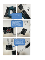
FITTING AN OPTION BOARD (CONT.)
Remove flexi from board
Fit 50 mm flexi to
board 9,
then insert board
Fit flexi to board 9
14 (cont.)
If fitting a board into option slot 7, re-
move the flexi-cable from the horizontal
connector of option board 5. Insert a
50 mm long flexi-cable into the vertical
connector of the new board. Slide the
option board into its slot, and connect
it to option board 5 using the 50 mm
flexi-cable just fitted. Take the flexi-cable previously
removed from option board 5, and fit it to the horizon-
tal connector of option board 7.
To fit option board 8, remove the flexi-cable from the
horizontal connector of option board 6 and insert it
into the horizontal connector of option board 8. Insert
a 50 mm long flexi-cable into the vertical connector
of option board 8 Slide the option board into its slot,
and use the 50 mm flexi-cable to connect to the hori-
zontal connector on option board 6.
To fit option board 9 (as shown), remove the flexi-ca-
ble from the horizontal connector of option board 8.
Insert a 50 mm long flexi-cable into the vertical con-
nector of option board 9. Slide the option board into
its slot, and use the 50 mm flexi-cable to connect to
the horizontal connector on option board 8.
Take the flexi-cable previously removed from option board 8, and insert it into the hori-
zontal connector of option board 9.

HA028908U180
Issue 3 Jly 10
HA028908U180
Issue 3 Jly 10
180 mm PAPERLESS GRAPHICS RECORDER: CIRCUIT BOARD RETROFIT INSTRUCTIONS 180 mm PAPERLESS GRAPHICS RECORDER: CIRCUIT BOARD RETROFIT INSTRUCTIONS
Page 11Page 10
FITTING A FURTHER INPUT BOARD (CONT.)
11b (cont.)
Fit new card
Connect 50 mm flexi
Fit 50mm
flexi
Disconnect flexi-cables
Re- connect flexi-cables
This cable disconnected
for ease of access
To fit input board 5. Fit a 270 mm long flexi-cable to
the input board's horizontal connector and slide it into
its slot.
If option boards 4 and/or 2 are fitted, remove the flexi-
cable which previously connected the option board(s)
with I/O 0 on the micro board. Use a 180 mm flexi-
cable to connect the horizontal connector on option
board 2 or 4 (whichever is physically the lower), to the
vertical connector of the new input board.
Connect the other end of the input board flexi to I/O 0
on the micro board.
To fit input board 6. Fit a 270 mm long flexi-cable to
the its horizontal connector and slide it into its slot.
12
FITTING AN OPTION BOARD
Continuing from instruction 10, set any relevant switches
or links, on the new board(s), as described on page 3.
See also the Board location rules on page 1. If necessary,
fit one or more circuit board support extensions. (The fig-
ure shows not only how to fit an extension, but also how
to fit a top support extrusion, which is necessary only when
fitting a board in option slot 1/2 or 5/6 for the first time.)
Notes:
1 Flexi-cable is not 'double sided'. At the ends, one face is 'live'; the other is insulated.
The insulated side of the flexi should always face the latching bar of the connector.
2. It may be necessary to disconnect some flexi cables, that are not directly associated
with the new board being fitted, in order to gain access to the board slot more easily.
3. See page 9 for a slot location drawing.
The following assumes that a new board is being fitted to a previously unused slot. If this
is not the case (e.g. a faulty board is being replaced), then the same length flexi-cables
should be used for the replacement board as were used on the board being replaced. It
is also assumed that only a single board is being fitted. If more than one board is being
fitted, the procedure is similar, but it must be ensured that the flexi-cable chains are ar-
ranged as shown electrically on page 2, and physically on page 8 or 9, according to ver-
sion.
If fitting a board into option slot 1, fit the board, and use a 180 mmm long flexi-cable to
connect it to input board 3 (if fitted), or to input board 1 (if fitted). If neither input board
is fitted, use a 270 mm long flexi-cable to connect the option board to I/O2 on the micro-
board.
If fitting a board into option slot 2, and neither input board 5 nor 7 is fitted, insert a 270
mm long flexi-cable into the horizontal connector and slide the board into its slot. Connect
the other end of this flexi to I/O 0 on the micro board. If either input board is fitted, con-
nect the horizontal connector of option board 2 to the vertical connector of input board 7
(if fitted) or board 5, using a 180 mm long flexi-cable.
If fitting a board into option slot 3, remove the flexi-cable fitted to the horizontal connec-
tor of Option board 1. Insert a 50 mm long flexi-cable into the vertical connector of the
new board. Slide the option board into its slot, and connect it to option board 1 using the
50 mm flexi-cable just fitted. Use a 180 mm long flexi-cable to connect the option board's
horizontal connector to the vertical connector of input board 3, if fitted, or input board 1 (if
fitted). If no input board is fitted, use a 270 mm flexi-cable to connect the option board to
I/O 2 on the microboard
To fit option board 4, remove the flexi-cable from option board 2, and insert it into the hor-
izontal connector of the new option board. Insert a 50 mm long flexi-cable into the vertical
connector. Slide the option board into its slot, and use the 50 mm flexi-cable to connect to
the horizontal connector on option board 2.
(Continued)
13
14
If option boards 6 and/or 8 and/or 9 are fit-
ted, remove the flexi-cable which previously
connected the option board(s) with I/O 3 on
the micro board. Use a 180 mm flexi-cable to
connect the horizontal connector on option
board 6, 8 or 9 (whichever is physically the
lowest), to the vertical connector of the new
input board.
Connect the other end of the input board flexi to I/O 3 on the
micro board.
To fit input board 7. Disconnect the flexi cable (if any) cur-
rently fitted to the vertical connector of input board 5. Fit a
50 mm long flexi-cable to this connector. Take the new input
board, and slide it into its slot. Connect its horizontal connec-
tor to the vertical connector of input board 5, using the 50
mm flexi-cable just fitted. Take the flexi-cable (if any) previ-
ously fitted to the vertical connector of input board 5, and fit
it to the vertical connector of input board 7.
To fit input board 8. Disconnect the flexi cable (if any) cur-
rently fitted to the vertical connector of input board 6. Fit a
50 mm long flexi-cable to this connector. Take the new input
board, and slide it into its slot. Connect its horizontal connector to the vertical connector of
input board 6, using the 50 mm flexi-cable just fitted. Take the flexi-cable (if any) previously
fitted to the vertical connector of input board 6, and fit it to the vertical connector of input
board 8. (If option slots 6, 8 or 9 are occupied, a flexi 180 mm long should be used.)
If option boards are also to be fitted, continue at instruction 13. If not, continue at instruc-
tion 15.
/