Page is loading ...


7451041 - V2.2
2
1. SCOPE .................................................................................................................................................. 3
2. WARNINGS AND HAZARDS .................................................................................................................. 3
3. AGENCY CERTIFICATIONS .................................................................................................................... 7
4. GENERAL DESCRIPTION ....................................................................................................................... 8
5. WV750 SERIES DESCRIPTION & INSTALLATION .................................................................................... 9
5.1 ANTENNA MOUNT - MAIN ASSEMBLIES ........................................................................................................ 9
5.2 WV750 INSTALLATION INFORMATION ........................................................................................................ 10
5.3 TRIA/E-TRIA ASSEMBLY ............................................................................................................................ 11
5.4 MAX CLEARANCES ................................................................................................................................... 16
6. CONTROLLER DESCRIPTION & CONFIGURATION................................................................................ 17
6.1 - FRONT PANEL CONNECTIONS & INTERFACES ............................................................................................... 18
6.2 - REAR PANEL CONNECTIONS ..................................................................................................................... 19
6.3 - MAIN MENU INTERFACE SCREEN .............................................................................................................. 20
6.4 - CONFIGURATION .................................................................................................................................... 20
6.5 - COMPASS SCREEN & FIXED HEADING MODE ............................................................................................... 32
6.6 - ADVANCED USER DATA ........................................................................................................................... 34
7. OPERATION ....................................................................................................................................... 38
7.1 - FIND SATELLITE...................................................................................................................................... 38
7.2 - STOWING ............................................................................................................................................. 42
8. SERVICE AND TROUBLESHOOTING .................................................................................................... 44
8.1 - THEORY OF OPERATION .......................................................................................................................... 44
8.2 - GLOBAL PROCEDURES ............................................................................................................................. 46
8.3 - MAINTENANCE PROCEDURES ................................................................................................................... 48
8.4 - CALIBRATION ........................................................................................................................................ 49
8.5 - SEARCH ROUTINE FLOWCHART ................................................................................................................. 52
8.6 - TROUBLESHOOTING ................................................................................................................................ 53
8.7 - MOTOR CONTROLS ................................................................................................................................ 55
8.8 - COMMUNICATIONS ................................................................................................................................ 60
9. REFERENCE MATERIALS ..................................................................................................................... 61
9.1 - UPPER AND LOWER CASE TRK .................................................................................................................. 61
9.2 - NULL MODEM ...................................................................................................................................... 61
9.3 - ON-SCREEN KEYPAD (WINDOWS CE) ........................................................................................................ 61
9.4 - WIRING DIAGRAM ................................................................................................................................. 62
10. WV750 TECHNICAL SPECIFICATIONS ................................................................................................ 63
11. INDOOR CONTROL UNIT TECHNICAL SPECIFICATIONS ..................................................................... 64
12. DECLARATION OF CONFORMITY ...................................................................................................... 65

7451041 - V2.2
3
1. Scope
The purpose of this document is to provide Installers, Technicians and End Users
with a complete Winegard WV750 Product manual which fulfills the roles of an
Installation Manual, Operation Manual and Service Manual.
2. Warnings and Hazards
Automated Machinery – The outdoor
antenna system may start moving
anytime the indoor controller is powered
on. Lock out/tag out procedures should
be followed before servicing. Servicing
should only be completed by trained,
authorized personnel.
There are no user serviceable parts inside
the unit.
Warning – Bodily Injury Hazard – The
antenna assembly may rotate around the
mount base. Keep fingers and other body
parts away.
Caution – Risk of Danger
Caution –
Crush Hazard

7451041 - V2.2
4
Warning – Pinch Hazard, Bodily Injury Hazard – Antenna support and lift
mechanism. Keep hands and other body parts away.
Warning – Pinch Hazard, Crush from Above, Bodily Injury Hazard –Feed arms and
mounting brackets. Keep hands and other body parts away.

7451041 - V2.2
5
Warning – Pinch Hazard, Crush from Above, Bodily Injury Hazard – Antenna support
brackets. Keep hands and other body parts away
Warning:
Automated machinery, the antenna may start moving at any time.
The antenna contains hazardous moving parts. Keep hands and other body parts
away. Follow lockout/tagout procedures before servicing equipment.

7451041 - V2.2
6
IDU Indoor Unit
The Winegard Indoor Electronics, or IDU, refers to the
2-Way Controller. The term IDU does not include the user
supplied modem or Ethernet distribution system.
Interchangeable words in the industry:
IDU
Controller
ACU
ODU Outdoor Unit
The Winegard Outdoor Electronics Unit, or ODU, refers to
The Outdoor electronics manufactured by Winegard which
are located on the antenna itself. It does not include the
TRIA/ETRIA (Viasat Radio) supplied by the user.
Interchangeable words in the industry:
ODU
Antenna Electronics
Antenna Winegard WV750 Antenna
Includes all physical components of the system except
the IDU. Motors, hardware links, ODU, Reflector and RF
Electronics are all components of the antenna.
Interchangeable words in the industry:
Antenna
Mount
System Winegard WV750 System
Includes all components supplied by Winegard. Motors,
hardware links, ODU, Reflector, RF Electronics and IDU are
all components of the System.
Interchangeable words in the industry:
System

7451041 - V2.2
7
3. Agency Certifications
FCC Part 15 Class B
The following model(s) have been tested and found to
be in compliance with Part 15 of the FCC rules for class
B devices. Operation of these devices is subject to the
following two conditions: (1) This device may not cause
harmful interference, and (2) this device must accept
any interference received, including interference that
may cause undesired operation.
Antenna Systems: WV750
Indoor Control Units: 7750190
CE Marking
The following model(s) have been tested and found to
be in compliance with all applicable EC directives.
(See Declaration of Conformity in Section 12 for
more details)
Antenna System: WV750
Indoor Control Unit: 7750190

7451041 - V2.2
8
4. General Description
Winegard manufactures several 2-Way Satellite Communication systems which can fill
different requirements in the satellite communication industry.
This manual covers the Winegard WV750 Antenna.
The Winegard WV750 series antenna is virtually maintenance free. Inspect the unit
regularly for physical damage, damaged wires and loose connections. Inspection intervals
will vary depending on usage and environment. Do not use the system if damage is
observed and contact Winegard for replacement parts.
The WV750 antenna systems are auto deploy, auto stow systems intended to be mounted
on the roof of a vehicle or mobile platform.
The WV750 antenna system consists of a high wind resistant mechanical antenna,
Outdoor Unit (ODU) and all wiring and motors required to point the system using the
Winegard 2-Way Controller. The model number for the appropriate controller is
OPT1018.
The WV750 series antenna accommodates the TRIA or E-TRIA supplied by Viasat.

7451041 - V2.2
9
5. WV750 Series Description & Installation
5.1 Antenna Mount - Main Assemblies
1. Reflector -
The WV750 antenna uses a Viasat reflector.
2. Elevation Motor -
The elevation motor is attached to the Reflector back plate and Main Drive
Mechanism
3. Main Drive Mechanism -
Houses the AZ motor, EL motor, ODU and wiring.
4. Installation Rail -
These are used to secure the antenna to the vehicle or mobile structure. Hole
patterns for installation are available in section 4.2.
5. Feed Arm -
Houses the TRIA/E-TRIA mounting plate which can be used to mount the user
supplied radio.
6. Wiring Plate -
The Power/Communication cable (from IDU) and Receive cable (from modem)
connect to the Antenna Mount Wiring Plate.

7451041 - V2.2
10
5.2 WV750 Installation Information
The Winegard WV750 antenna should be mounted to a secure platform using the
rails provided. The following diagrams show the mounting point dimensions as
well as the wiring panel at the base of the antenna.
1. Mounting points -
All mounting points should be connected to a cross member or secure mounting
point on the vehicle roof or mobile platform. Use 8 – 3 /8 inch x 1 inch (10 mm x
25 mm) Grade 8 bolts with washers and appropriate lock nut.
2. Wiring Bulkhead-
The RX cable is F connector terminated to go directly to the modem.
The ODU power/communication cable is F connector terminated and connects
the antenna to the Winegard 2-Way Controller ODU port. The picture below
shows the wiring plate.

7451041 - V2.2
11
5.3 Tria/E-Tria Assembly
1. Tria Assembly –

7451041 - V2.2
12

7451041 - V2.2
13

7451041 - V2.2
14
2. ETria Assembly –

7451041 - V2.2
15

7451041 - V2.2
16
5.4 Max Clearances
The Max Horizontal and Vertical clearances should be considered when deciding
where to install the antenna.

7451041 - V2.2
17
6. Controller Description & Configuration
The IDU controller is the central decision making center in the Winegard WV750 Satellite
Communications System.
The Controller sends commands to the ODU, which in turn moves the motors and keeps
records of the motor counts, states etc.
The control data is sent to the ODU thru the Power/Communications Cable which carries
the control data as well as power for the ODU.
Data about the antenna type, state, position and calibration is stored in the ODU.
The Winegard 2-Way controller is simple to configure and operate. The system works out
of the box with the Viasat modem.
The controller is simple to upgrade using a Flash drive and the built in touch screen.
The Indoor Control Unit (IDU) is rack mountable. It fits in a standard 19 inch rack and is 2
units (3.5 inches) tall.
If the IDU is mounted in a rack the operating ambient temperature of the rack
environment may be greater than the ambient room temperature. Care should be taken
not to exceed the max IDU operating temperature of 50˚C (120°F). Installation of the IDU
controller in a rack should be such that air flow required for safe operation is not
compromised.
If mounting the IDU in a rack, use the rack manufacturers recommended mounting
hardware. Ensure the mounting is such that a hazardous condition is not achieved due to
uneven loading.
Make sure the rear of the IDU is supported when rack mounted (P/N OPT1048).

7451041 - V2.2
18
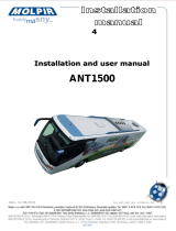
6.1 - Front Panel Connections & Interfaces
The front panel of the controller contains the following components:
1. Power Button -
The Power Button is dark when the controller is in stand by and will illuminate
bright green when the controller is powered on. This button does not completely
shut power off when in stand by mode. The AC power must be disconnected in
order to completely power the system down.
2. USB Host Connector -
The USB host is primarily utilized for firmware updates using a Flash (Thumb)
drive but can also host a keyboard or mouse. One additional USB Host Connector
is available on the rear panel. Information about updating the software on the
controller can be found in the “Update screen” section on page 37.
3. Touch Screen -
The Touch Screen is the main interface to the controller.
It is a fully interactive color screen which provides User Interaction, Configuration
and Troubleshooting screens dynamically depending on the current process.
Tapping the screen makes selection of functions and decision during configuration
a simple and effective process.
Power On/Standby
Symbol
Power On/Standby
Button
Touch Screen
Front Panel USB Port

7451041 - V2.2
19
6.2 - Rear Panel Connections
1. Ethernet Ports -
The controller features a 3 port 10/100 switch.
2. Mini USB Port -
The USB Mini Port is a client port utilized at the factory.
3. USB Host Port -
Available to connect USB devices such as a Keyboard, Memory Device or Mouse.
4. Serial RS232 Output Port -
The Serial port is used to output system information either while operational or
troubleshooting.
5. ODU Power/Communication Port (ODU) -
The Power/Communication Port is a Female F bulkhead connector. This connects
to the Power/Communication Port on the Antenna System.
6. AC Power Plug -
The system is supplied with a UL listed 120VAC power cord. See section 10 for
power cord specifications. The power cord must be connected to a grounded
socket-outlet protected by a 20 amp fuse or circuit breaker. The power cord is the
disconnecting device. The socket-outlet for the power cord shall be installed near
the equipment and be easily accessible. If the IDU is installed in a rack
accessibility must be provided to the power cord or to the fuse or circuit breaker
for disconnection.
7. Remote -
Connection for a remote status indicator.
8. Fuse -
5A 32V Fast Acting Type ATF. Winegard P/N 2320020
9. Model/Serial Number Label
This label contains the model number a serial number of the IDU.
This label contains logos for all agency certifications.
6
4
3
5
9
7
2
6
1
8

7451041 - V2.2
20
6.3 - Main Menu Interface Screen
The Winegard 2-Way Controller’s Main Menu Interface Screen is the primary means for
deploying and stowing the system.
It provides links at the top of the screen to the Authorized Installer menu (yellow
triangle) for configuration of the system as well as the Advanced User Data section
(wrench) to see live data, network configuration and firmware update screen.
At the bottom of the screen you can see the Signal Strength as well as the Compass
Heading and Mode.
The currently running version of the software is listed below the Authorized Installer
and Advanced User Data icons.
Deployment and Stow buttons are available in the middle section of the screen.
Below is a capture of the Main Menu Screen:
6.4 - Configuration
The Winegard 2-Way Controller is a versatile system that allows connection to and
operation of the WV750 Antenna System.
/