Page is loading ...

1
Equipped with AEM
®
Dryflow™ Filter
No Oil Required!
INSTALLATION INSTRUCTIONS
PART NUMBER
21-831C (GUN METAL GRAY FINISH)
2017 SUBARU FORESTER 2.5L

2
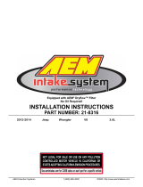
ITEM NO. PART NUMBER DESCRIPTION QTY.
1 21-2027DK Element; 2 3/4” flange 5 1/2” B, 4 3/4 L 1
2 2-1592-1C INTAKE TUBE; 2.75" OD X 49", 4" BR; 21-808 1
3 20-8606 HEAT SHIELD, SUBARU FORESTER 2017 2.5L, TB/PC 1
4 08185 Hose; 2-3/4" ID X 2-1/2" L Hump Reinforced 1
5 5-5008 Hose; 1/2" ID x 8" L 1
6 8-117 Connector , Plastic 1/2" Blk 1
7 1228599 Mount; Rubber 1" x 6mm 1
8 22224 Bolt; M6-1.00x12 Hex; Flg, Grade 10.9 1
9 444.460.04 Nut; M6 Hex Serrated 1
10 08160 Washer; 1" D x 1/4" Hole Fender 1
11 9444 HOSE CLAMP; 2.31-3.25" 2
12 9448 1/2" BNDHOSE CLAMP, 2.56" - 3.50" 1
13 1-2105 BOLT; SOCKET M4-.7 X 8MM 2
14 102466 Edge Trim; 1/16' Gap 12" 1
15 102496 EDGE TRIM; 3/4" BULB, TOP LOC, 39"L 1

3
Read and understand these instructions BEFORE attempting to install this product. Failure to follow installation
instructions and not using the provided hardware may damage the intake tube, throttle body and engine. If you
need any assistance please call1-800-858-3333 to speak with a representative in our Customer Service Center
before returning the product.
1. Preparing Vehicle
a. Make sure vehicle is parked on level surface.
b. Set the parking brake.
c. If engine has run in the past two hours, let it cool down.
d. Disconnect negative battery terminal.
e. Do not discard stock components after removal of the factory system.
f. Open the air intake kit package and make sure all parts are included.
2. Removal of stock system
a. Remove the factory air scoop by removing the two
push-in plasc fasteners.
b. Remove the push-in plasc fastener securing the in-
take resonator to the intake manifold.
c. Disconnect the PCV hose from the intake resonator
by releasing the pressure on the spring clamp.
d. Disconnect the Mass Air Flow (MAF) sensor harness
from the MAF sensor and the air box.
Tools Needed:
Screwdriver
10mm Socket
Socket Driver
Side Cuers
4mm Hex Key
Oponal:
Small Torque
Wrench

4
e. Loosen the hose clamp securing the factory intake to
the throle body.
f. Unlatch the air box lid and remove the air box lid and
intake resonator assembly out of the engine bay.
g. Remove the two nuts and the bolt securing the air
box base in the engine bay. The nuts will be reused in
step 3g.
h. Li the air box up and out of the engine bay. Tuck the
MAF sensor harness towards the engine so it is out of
the way.
i. Remove the MAF sensor from the air box lid assembly.
Replace the screws into the air box lid for safe keeping.
Do not discard any of your stock equipment.

5
3. Installation of AEM
®
intake system.
a. When installing the intake system, do not completely tighten the hose clamps or mounting hardware until
instructed to do so.
a. Install the MAF sensor into the AEM intake tube using
the provided hardware.
d. Install the edge trim onto the heat shield as shown.
Install the rubber mount using the provided hardware.
Leave the top nut and washer loose to aid in installaon
of the intake tube.
b. Aach the provided hose and hose ng to the in-
take tube nipple.
c. Install the provided coupler on to the throle body
using the provided hose clamps. Tighten the throle-
body-side hose clamp at this me.

6
e. Install the intake tube as shown, sliding the bracket
below the washer on the rubber mount. Do not fully
ghten the nut to allow some movement during installa-
on.
f. Install the AEM DryFlow lter using the provided hose
clamp onto the intake tube.
h. Insert the intake tube into the coupler. Posion the
tube for best t and ghten the hose clamp.
i. Connect the factory PCV hose to the supplied hose and
secure using the factory spring clamp.
j. Connect the MAF sensor harness to the MAF sensor
and secure the harness on the heatshield. Tighten the
nut on the bracket to secure the tube.
g. Carefully lower the assembly into the engine bay. It
will take some maneuvering to seat the heatshield as-
sembly into place. Fasten using the provided bolt and
the nuts removed in step 2g.

7
4. Reassemble Vehicle
a. Position all kit components for best fitment. Ensure that no components contact any unintended part of the vehicle.
b. Check for proper hood clearance. Re-adjust components if necessary and re-tighten them.
c. Inspect the engine bay for any loose tools and ensured that all fasteners that were moved or removed are properly
tightened.
d. Reconnect negative battery terminal and start engine. Let the vehicle idle for 3 minutes. Perform a final inspection
before driving the vehicle.
5. Service and Maintenance
a. AEM Induction Systems requires cleaning the intake system’s air filter element every 100,000 miles. When
used in dusty or off-road environments, our filters will require cleaning more often. We recommend that you
visually inspect your filter once every 25,000 miles to determine if the screen is still visible. When the screen
is no longer visible some place on the filter element, it is time to clean it. To clean, purchase our Synthetic air
filter cleaner, part number 1-1000 and follow the easy instructions.
b. Use window cleaner to clean your powder coated AEM
®
intake tube.
NOTE: DO NOT USE aluminum polish on powder coated AEM
®
intake tubes.
For technical inquiries
e-mail us at
sales@aemintakes.com
or
call us at
800.992.3000
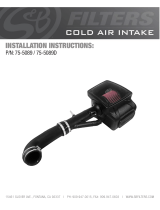
STOCK INTAKE INSTALLED
AEM INTAKE INSTALLED

8
AEM Air Intake System Warranty Policy
AEM
®
warrants that its intake systems will last for the life of your vehicle. AEM
®
will not honor this warranty due to me-
chanical damage (i.e. improper installation or fitment), damage from misuse, accidents or flying debris. AEM
®
will not
warrant its powder coating if the finish has been cleaned with a hydrocarbon-based solvent. The powder coating should
only be cleaned with a mild soap and water solution. Proof of purchase of both the vehicle and AEM
®
intake system is
required for redemption of a warranty claim.
This warranty is limited to the repair or replacement of the AEM
®
part. In no event shall this warranty exceed the original
purchase price of the AEM
®
part nor shall AEM
®
be responsible for special, incidental or consequential damages or cost
incurred due to the failure of this product. Warranty claims to AEM
®
must be transportation prepaid and accompanied
with dated proof of purchase. This warranty applies only to the original purchaser of product and is nontransferable. Im-
proper use or installation, use for racing, accident, abuse, unauthorized repairs or alterations voids this warranty. AEM
®
disclaims any liability for consequential damages due to breach of any written or implied warranty on all products manu-
factured by AEM
®
. Warranty returns will only be accepted by AEM
®
when accompanied by a valid Return Merchandise
Authorization (RMA) number. Credit for defective products will be issued pending inspection. Product must be received
by AEM
®
within 30 days of the date RMA is issued.
If you have a warranty issue, please call (800) 992-3000 and our customer service department will assist you. A
proof of purchase is required for all AEM
®
warranty claims.
10-119 10/06/17
/