Page is loading ...

Turbonetics, Inc. * 2255 Agate Court * Simi Valley, CA * 805-581-0333 * TurboneticsInc.com
INSTALLATION INSTRUCTIONS
TURBOCHARGER SYSTEMS:
2004- Scion TC
Manual Transmission Only
P/N 15152 (No Catalytic Converter)

60133 revG Page 2 of 38
READ THIS FIRST: Study these instructions completely before proceeding. Engine and/or turbocharger damage
may occur if any component within these instructions is improperly installed. Turbonetics, Inc or any of its
distributors cannot be held responsible for damages as a result of negligent or improper installation. This
complete turbocharger system can be installed using common tools and automotive procedures, but installer must
have a thorough knowledge of automotive engine operation and feel comfortable working on the vehicle. If in
doubt, contact Turbonetics’ technical support staff at 805-581-0333, between the hours of 8:00AM and 5:00PM
PST, Monday through Friday.
Remove the turbocharger system from its carton and inspect for any obvious physical damage. All kit
components are thoroughly inspected and carefully packaged prior to shipment from the factory. If any shipping
damage is evident, contact your supplier and request that they process a claim with the shipper involved. Be sure
to review the parts list on page 3 to verify that you have all necessary system components to proceed. If any
components in the parts list are missing, contact Turbonetics’ customer service staff.
Although this turbocharger system has been designed to use many of the factory emissions controls, it is not
currently “smog” legal in California, and therefore recommended for “off road” use only. In other states, check
local laws regarding aftermarket modification to emission controlled vehicles.
The information contained in this publication was accurate and in effect at the time the publication was approved
for printing and is subject to change without notice or liability. Turbonetics reserves the right to revise the
information presented herein or to discontinue the production of parts described at any time.
SAFETY REQUIREMENTS: It is recommended to follow these precautions.
• Always wear safety glasses & gloves.
• Turn the ignition switch to the OFF position & disconnect the battery.
• Always use properly rated jack stands when working under the vehicle.
• Prevent unexpected vehicle movement by using wheel chocks and/or parking brake.
• Operate the vehicle only in well ventilated areas.
• Do not smoke or use flammable items near or around the vehicle’s fuel system.
• Keep hands, clothing and other objects away from moving parts when engine is running.
SUPPLIES: It is recommended to have the following items before beginning installation.
• Toyota factory service manual, for your model year Scion TC
• A large table or bench, and plenty of adjacent available workspace
• Standard selection of automotive tools, primarily metric sizes
• An assortment of “zip ties” and/or thin-gauge steel wire
• The ability to securely lift the vehicle at least a few feet off the ground
• High temp. automotive RTV sealant
• NPT thread sealant
• Replacement engine oil and oil filter
• Hammer

60133 revG Page 3 of 38
TORQUE RECOMMENDATION: When removing and re-installing factory fasteners, refer to the Toyota / Scion
service manual for torque values. When installing fasteners included in this kit, refer to the following chart:
Fastener
Size
Torque
(Pound-Feet)
Torque
(Newton-Meters)
1/4" or 6mm 10 13
5/16” or 8mm 19 25
3/8” or 10mm 33 45
NPT fittings 2-3 turns past finger tight
TURBOCHARGER SYSTEM PARTS LIST:
QTY P/N DESCRIPTION P/N 15152
1 11118 Turbocharger, E50 / Stg.2 / Ball Bearing X
1 5-340 Air to Air Intercooler, Spearco X
1 10781 Wastegate, Evolution X
1 10843 Blow-off Valve, Raptor X
1 11124 Hardware Kit, Nuts / Bolts / Fittings / Misc. X
1 11126 Hardware Kit, Fuel Components X
1 21239 Tube, Turbocharger to Intercooler X
1 21240 Tube, Intercooler to Throttle Body – 1 X
1 21241 Tube, Intercooler to Throttle Body – 2 X
1 21242 Tube, Intercooler to Throttle Body – 3 X
1 21238 Tube, Air filter to Turbocharger X
1 21243 Tube, Exhaust, Downpipe X
1 21279 Manifold, Exhaust X
1 31040 Heat Shield, Tangential T3 housing X
1 31080 Air Filter, AEM Dry-Flow, 3.0” Inlet X
1 21286 Fuel Controller, UniChip X
1 60133 Install Instructions X

60133 revG Page 4 of 38
QTY P/N DESCRIPTION QTY P/N DESCRIPTION
HOSES / CLAMPS PARTS LIST:
2 30128-4 Silicone Hose Coupling, 2.0”
1 30162-4 Silicone Hose Coupling, 3.0”
1 30172-4 Silicone Hose Coupling, 2.50”
1 21364 Silicone Hose Coupling, 2.50”
x 6.50” long
1 30380-4 Silicone Hump Connector,
2.50”
1 30444-4 Silicone 45’ Elbow, 2.50”
3 ft. 30827 Hose, Oil Drain – 5/8”
1 31072-4 Silicone Hose Coupling, 1.50”
4 30275-200 T-Bolt Clamp – 2.0”
8 30275-250 T-Bolt Clamp – 2.50”
2 30275-300 T-Bolt Clamp – 3.00”
HARDWARE KIT# 11124 (NUTS / BOLTS / FITTINGS) PARTS LIST:
1 30133 Fitting, 3/8” NPT x 5/8” Hose,
Straight
4 30306 Fitting, 1/8” NPT x 5/32” Hose,
Straight
4 30307 Fitting, 1/8” NPT x 5/32” Hose,
Elbow
1 30544 Fitting, 1/8” NPT x -3, Straight
1 30551 Fitting, 1/8” NPT x -3, Elbow
1 30562 Fitting, 1/8” NPT, M x M x F
1 30244 Fitting, ½” NPT x 5/8” Hose,
Straight
1 31068 Fitting, Hose Tee - Nylon
2 30570 Hex Bolt, 5/16 -18 x 1.0" Lg.
4 30739 Hex Bolt, M8-1.25 x 25mm Lg.
3 30700 Hex Bolt, M8-1.25 x 20mm Lg.
2 30248 Hex Bolt, 1/4-20 x 5/8” Lg.
1 31003 Hex Bolt, M10-1.25 x 40mm Lg.
2 31071 Screw, M4-0.7 x 10mm, BHCS
9 30589 Flat Washer, 5/16” or M8
6 30804 Flat Washer, M10
1 30591 Flat Washer, 1/4" or M6
9 30593 Lock Washer, 5/16” or M8
5 30805 Lock Washer, M10
1 30586 Hex Nut, Nylon Lock
2 30653 Hex Nut, M8
5 30803 Hex Nut, M10-1.25
4 30806 Stud, M10-1.25 x 42mm Lg.
2 30860 Stud, M8-1.25 x 30mm Lg.
1 30862 Hex Plug for O2 Bung, M18-1.5
1 31067 Mount, Vibration Damping – Blk.
1 20259 Flange, Oil Drain – ½” NPT
1 21273 Tool, Center Punch
1 21376 O2 Sensor Ext. Boss
1 30808 Tap, 1/8 NPT
1 30809 Tap, 3/8 NPT
1 20142 Gasket, Wastegate
1 30468 O-Ring, Blow off Valve
2 30612 Clamp, Hose, Liner Style #020
4 30817 Clamp, Hose, Worm Drive, 5/8”
1 31014 Oil Supply Hose, -3 x 12”
1 31007 Heat Shield Wrap – 1.5” Wide x
7.5” Long
12 30542-
BK
Hose, Vacuum, Silicone – 5/32”
HARDWARE KIT #11126 (FUEL COMP’TS) PARTS LIST:
4 21382 Fuel Injector, Upgrade
4 31079 Pig Tail Harness, Fuel Injector

60133 revG Page 5 of 38
P/N 11118 P/N 5-340 P/N 10781
P/N 10843 P/N 11124
P/N 21238 P/N 11126 P/N 21241
P/N 21240 P/N 21242 P/N 21239

60133 revG Page 6 of 38
P/N 21243 P/N 31040 P/N 21279
P/N 21286 P/N 31080 P/N 60133

60133 revG Page 7 of 38
Prepping the Vehicle for Turbo Kit Installation
1. Jack up the vehicle to a workable height and secure vehicle with jack stands. SEE FIGURE 1
FIGURE 1
2. Using a 10mm socket, remove undercarriage plastics splash guard. SEE FIGURE 2 & 3
FIGURE 2 FIGURE 3
Removing the Front Fascia
1. Using a 10mm socket, remove the bolt inside the fender well. SEE FIGURE 4 & 5
FIGURE 4 FIGURE 5

60133 revG Page 8 of 38
2. Using a small flat head screwdriver, carefully insert the screwdriver in the indented slot on the plastic trim
clip and pry upwards. SEE FIGURES 6, 7, & 8
FIGURE 6 FIGURE 7
FIGURE 8
3. Remove front fasica by pulling it forward
4. Remove foam bumper reinforcement. SEE FIGURE 9
FIGURE 9
5. Remove plastic air dams on each side of the vehicle. Air dams are secured to the vehicle with the plastic
trim clips that can easily be removed by using a flat head screwdriver. SEE FIGURE 10

60133 revG Page 9 of 38
FIGURE 10
Exhaust Disassembly
1. Unplug O2 sensor and remove the plastic securing ring that holds the wire to the radiator hose. SEE
FIGURE 11
FIGURE 11
2. Remove the cosmetics plastic engine cover by unscrewing two 10mm nuts. SEE FIGURE 12
FIGURE 12

60133 revG Page 10 of 38
3. Remove the factory exhaust head shield by unscrewing the three 12mm bolts and one 12mm nut. SEE
FIGURE 13 & 14
FIGURE 13 FIGURE 14
Note: Careful while removing the heat shield, it tends to get caught up with the O2 sensor and other things in
the area.
4. Unscrew the O2 sensor with a 7/8” open end wrench or with a O2 sensor socket. SEE FIGURE 15
FIGURE 15
5. Using a 14mm socket, remove the stock catalytic converter support brackets. SEE FIGURE 16 & 17
FIGURE 16 FIGURE 17

60133 revG Page 11 of 38
6. Unbolt spring loaded bolts that connects the stock catalytic converter to the down pipe. SEE FIGURE 18
FIGURE 18
7. Save the exhaust crush ring gasket, this will be used when installing the new supplied down pipe.
8. Remove the five bolts that hold the stock exhaust manifolds to the head with a 12mm wrench. SEE
FIGURE 19
FIGURE 19
Stock Intake Disassembly
1. Unplug the mass air sensor and remove the two Phillips screws that mounts the sensor to the factory air
box. SEE FIGURE 20
FIGURE 20

60133 revG Page 12 of 38
2. Carefully lift the mass air sensor out of the factory air box and set it aside. You will be re-installing the
sensor on a supplied intake pipe at a later time.
3. Remove the engine breather hose by pinching the tabs on the hose clamps with your finger or a pair of
pliers and push the clamp away from the motor. SEE FIGURE 21
FIGURE 21
4. Loosen hose clamp that connects the intake tube to the air box. SEE FIGURE 22
FIGURE 22
5. Remove the factory intake tube that connects to the throttle body by pinching the tabs on the hose clamp
with a pair of pliers. SEE FIGURE 23
FIGURE 23

60133 revG Page 13 of 38
6. Remove the sensor that is mounted to the factory intake tube by inserting a small flat head screwdriver
between the sensor bracket and the intake tube bracket. SEE FIGURE 24
FIGURE 24
7. Remove the factory air box by unbolting the three 10mm bolts inside. SEE FIGURE 25
FIGURE 25
8. Remove the factory cold air intake tube by unscrewing the Phillips screw that mounts the factory cold air
intake tube to the body. There is another Phillips screw that holds the tube to the body, that screw does
not need to be removed, the tube bracket slides underneath that screw only. SEE FIGURE 26
FIGURE 26

60133 revG Page 14 of 38
Fuel System Upgrade
1. Cut the vacuum hose that connects to the throttle body in half and install the supplied T-fitting in the
orientation. SEE FIGURE 27 & 28
FIGURE 27 FIGURE 28
2. Unplug the four factory injectors by squeezing the tab on the side of the plugs and pulling upwards.
3. Disconnect the plug to the VVTi actuator by the passenger side of the fuel rail.
4. Unbolt both 12mm nuts that holds the fuel rail to the head. SEE FIGURE 29
FIGURE 29
5. Remove the fuel rail from the head and set the fuel rail on the top of the head. SEE FIGURE 30
FIGURE 30

60133 revG Page 15 of 38
6. Remove stock fuel injectors from the fuel rail. Careful not to lose any of the o-rings when removing them.
7. Connect the new supplied injector pig tails to the factory harness by cutting the stock injector connector
plugs off the factory harness. Cut wires around 2 ¾” from the edge of the connector, leaving enough wire
length to connect the new plugs. SEE FIGURE 31
FIGURE 31
8. Crimp the new supplied connectors to the factory harness. Make sure the polarities are correct. SEE
FIGURE 32 & 33
a. Wires colored blue, red, yellow, and white are positive (+)
b. Wires colored black are negative (-)
FIGURE 32 FIGURE 33

60133 revG Page 16 of 38
9. Remove the o-rings from both the top and bottom of the stock injector and install them on the new
supplied injectors (P/N 21382). SEE FIGURE 34, 35, & 36
FIGURE 34 FIGURE 35
FIGURE 36
10. Slightly coat the outside of both o-rings with grease to ease installation of the injectors to the head and
the rail.
11. Carefully insert the injector to the bungs on the head making sure the o-rings does not get kinked. Make
sure the injector plugs are facing toward the passenger side.
12. Re-install the factory fuel rail. Once the rail is on, tighten the bolts slightly with your finders. Do not
tighten the rail to the head yet; slightly twist the injectors back and forth to make sure all the injectors are
seated properly.
13. With all injector plugs facing the passenger side, plug the injector harness to the injectors.
14. Once all the injectors are plugged, slightly twist the injectors so all the injector plugs are facing toward the
rear of the vehicle. This will allow the injectors’ spray pattern to correctly match the factory spray pattern.
15. Tighten the two nuts that holds the rail to the head.
STOCK SUPPLIED
STOCK SUPPLIED
UPGRADE
INJECTOR
P/N #21382

60133 revG Page 17 of 38
Installing Turbo Oiling System
Turbo Oil Feed
1. Locate the oil sending unit on the driver’s side of the head. On top of the radiator hose connection. SEE
FIGURE 37
FIGURE 37
2. Unplug the wires that are connected to the sensor and using a 24mm socket, remove the sensor from the
head.
3. Re-tap the threaded hole using the supplied 1/8-27 NPT tap. Make sure you coat the tap with a lot of
grease so no chips from the re-thread will enter the motor.
4. Apply a small amount of thread sealant to the threads of the sensor and install the factory oil sensor to
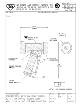
the supplied brass T fitting as shown in the picture below. It is recommended that you use a liquid thread
sealant. When using a tape style thread sealant, make sure the tape does not get into the oil passages.
5. Hand thread the brass T fitting to the head and use a 24mm socket to tighten.
6. Once the T fitting is tighten, make sure the threaded port of the fitting is facing toward you with a slight
angle upwards. SEE FIGURE 38
7. Install and tighten the supplied brass 1/8 NPT to -3AN fitting to the threaded port on the T- fitting. Apply a
small amount of thread sealant to the threads of the fitting. SEE FIGURE 38
FIGURE 38

60133 revG Page 18 of 38
Turbo Oil Drain
1. Using the supplied center punch (P/N #21273) and a hammer, punch a hole through the oil pan. Do not
use a drill, by using a center punch, the material that bends over is used for threading. SEE FIGURE 39,
40, & 41
FIGURE 39
FIGURE 40 FIGURE 41
2. Coat the supplied 3/8” NPT tap (P/N #30809) with grease to insure no metal debris will enter the pan and
tap the hole you just made. SEE FIGURE 42
FIGURE 42
~2.25”
~1.0”

60133 revG Page 19 of 38
3. Apply a small amount of high temp RTV to the threads of the supplied 3/8” NPT to 5/8” barb brass fitting
(P/N #30133) and the threads in the oil pan as shown in the picture below. Thread the fitting into the pan
and tighten. SEE FIGURES 43, 44, & 45
FIGURE 43 FIGURE 44
FIGURE 45
Assembling the Turbo and Mounting it to the Manifold
1. Thread the four supplied M10x1.25 studs (P/N #30806) onto the turbo mounting pad on the manifold.
SEE FIGURE 46
FIGURE 46
EXHAUST MANIFOLD P/N #21279
TURBO MOUNTING
FLANGE
FITTING P/N #30133

60133 revG Page 20 of 38
2. Slide the supplied turbo inlet gasket (P/N #30263) onto the four studs and mount turbocharger onto the
manifold as shown in picture 47.
3. Secure the turbocharger to the manifold using the supplied flat washer (P/N #30804), lock washer (P/N
#30805), and nut (P/N #30803), in those respective order. SEE FIGURE 47
FIGURE 47
4. Install the supplied oil drain flange (P/N #20259) to the turbocharger with a supplied oil drain gasket (P/N
# 30141)in the middle. Secure the flange to the turbocharger using the supplied M8-1.25 (P/N #30700)
bolt with a lock washer.
5. Apply a small amount of liquid thread sealant or thread tape to the supplied brass ½” NPT to 5/8” hose
barb fitting (P/N #30244) and thread onto the oil drain flange. Tighten fitting with a 7/8” open wrench or
socket.
6. Thread the two supplied M8 x 1.25 studs (P/N #30860) onto the wastegate mounting pad on the manifold.
SEE FIGURE 48
FIGURE 48
7. Mount the Evolution wastegate (P/N #10781) to the manifold using the supplied M8 lock washers (P/N
#30593) and M8 nuts (P/N #30653). Hand tight the nuts only.
8. Apply a thin layer of RTV high temp. silicone to the turbocharger side of the downpipe (P/N #21243).
SEE FIGURE 49 & 50
EXHAUST MANIFOLD #21279
WASTEGATE MOUNTING FLANGE
/