Campbell Scientific 27106T Owner's manual
- Category
- Measuring, testing & control
- Type
- Owner's manual

INSTRUCTION MANUAL
27106T Vertical Propeller
Anemometer
Revision: 4/16
Copyright © 1984- 2016
Campbell Scientific, Inc.


Limited Warranty
“Products manufactured by CSI are warranted by CSI to be free from defects in
materials and workmanship under normal use and service for twelve months
from the date of shipment unless otherwise specified in the corresponding
product manual. (Product manuals are available for review online at
www.campbellsci.com.) Products not manufactured by CSI, but that are resold
by CSI, are warranted only to the limits extended by the original manufacturer.
Batteries, fine-wire thermocouples, desiccant, and other consumables have no
warranty. CSI’s obligation under this warranty is limited to repairing or
replacing (at CSI’s option) defective Products, which shall be the sole and
exclusive remedy under this warranty. The Customer assumes all costs of
removing, reinstalling, and shipping defective Products to CSI. CSI will return
such Products by surface carrier prepaid within the continental United States of
America. To all other locations, CSI will return such Products best way CIP
(port of entry) per Incoterms ® 2010. This warranty shall not apply to any
Products which have been subjected to modification, misuse, neglect, improper
service, accidents of nature, or shipping damage. This warranty is in lieu of all
other warranties, expressed or implied. The warranty for installation services
performed by CSI such as programming to customer specifications, electrical
connections to Products manufactured by CSI, and Product specific training, is
part of CSI's product warranty. CSI EXPRESSLY DISCLAIMS AND
EXCLUDES ANY IMPLIED WARRANTIES OF MERCHANTABILITY
OR FITNESS FOR A PARTICULAR PURPOSE. CSI hereby disclaims,
to the fullest extent allowed by applicable law, any and all warranties and
conditions with respect to the Products, whether express, implied or
statutory, other than those expressly provided herein.”

Assistance
Products may not be returned without prior authorization. The following
contact information is for US and international customers residing in countries
served by Campbell Scientific, Inc. directly. Affiliate companies handle repairs
for customers within their territories. Please visit www.campbellsci.com to
determine which Campbell Scientific company serves your country.
To obtain a Returned Materials Authorization (RMA), contact CAMPBELL
SCIENTIFIC, INC., phone (435) 227-9000. After an application engineer
determines the nature of the problem, an RMA number will be issued. Please
write this number clearly on the outside of the shipping container. Campbell
Scientific’s shipping address is:
CAMPBELL SCIENTIFIC, INC.
RMA#_____
815 West 1800 North
Logan, Utah 84321-1784
For all returns, the customer must fill out a “Statement of Product Cleanliness
and Decontamination” form and comply with the requirements specified in it.
The form is available from our website at www.campbellsci.com/repair. A
completed form must be either emailed to repair@campbellsci.com or faxed to
(435) 227-9106. Campbell Scientific is unable to process any returns until we
receive this form. If the form is not received within three days of product
receipt or is incomplete, the product will be returned to the customer at the
customer’s expense. Campbell Scientific reserves the right to refuse service on
products that were exposed to contaminants that may cause health or safety
concerns for our employees.

Safety
DANGER — MANY HAZARDS ARE ASSOCIATED WITH INSTALLING, USING, MAINTAINING, AND WORKING ON OR AROUND
TRIPODS, TOWERS, AND ANY ATTACHMENTS TO TRIPODS AND TOWERS SUCH AS SENSORS, CROSSARMS, ENCLOSURES,
ANTENNAS, ETC. FAILURE TO PROPERLY AND COMPLETELY ASSEMBLE, INSTALL, OPERATE, USE, AND MAINTAIN TRIPODS,
TOWERS, AND ATTACHMENTS, AND FAILURE TO HEED WARNINGS, INCREASES THE RISK OF DEATH, ACCIDENT, SERIOUS
INJURY, PROPERTY DAMAGE, AND PRODUCT FAILURE. TAKE ALL REASONABLE PRECAUTIONS TO AVOID THESE HAZARDS.
CHECK WITH YOUR ORGANIZATION'S SAFETY COORDINATOR (OR POLICY) FOR PROCEDURES AND REQUIRED PROTECTIVE
EQUIPMENT PRIOR TO PERFORMING ANY WORK.
Use tripods, towers, and attachments to tripods and towers only for purposes for which they are designed. Do not exceed design limits.
Be familiar and comply with all instructions provided in product manuals. Manuals are available at www.campbellsci.com or by
telephoning (435) 227-9000 (USA). You are responsible for conformance with governing codes and regulations, including safety
regulations, and the integrity and location of structures or land to which towers, tripods, and any attachments are attached. Installation
sites should be evaluated and approved by a qualified engineer. If questions or concerns arise regarding installation, use, or
maintenance of tripods, towers, attachments, or electrical connections, consult with a licensed and qualified engineer or electrician.
General
• Prior to performing site or installation work, obtain required approvals and permits. Comply
with all governing structure-height regulations, such as those of the FAA in the USA.
• Use only qualified personnel for installation, use, and maintenance of tripods and towers, and
any attachments to tripods and towers. The use of licensed and qualified contractors is highly
recommended.
• Read all applicable instructions carefully and understand procedures thoroughly before
beginning work.
• Wear a hardhat and eye protection, and take other appropriate safety precautions while
working on or around tripods and towers.
• Do not climb tripods or towers at any time, and prohibit climbing by other persons. Take
reasonable precautions to secure tripod and tower sites from trespassers.
• Use only manufacturer recommended parts, materials, and tools.
Utility and Electrical
• You can be killed or sustain serious bodily injury if the tripod, tower, or attachments you are
installing, constructing, using, or maintaining, or a tool, stake, or anchor, come in contact with
overhead or underground utility lines.
• Maintain a distance of at least one-and-one-half times structure height, 20 feet, or the distance
required by applicable law, whichever is greater, between overhead utility lines and the
structure (tripod, tower, attachments, or tools).
• Prior to performing site or installation work, inform all utility companies and have all
underground utilities marked.
• Comply with all electrical codes. Electrical equipment and related grounding devices should be
installed by a licensed and qualified electrician.
Elevated Work and Weather
• Exercise extreme caution when performing elevated work.
• Use appropriate equipment and safety practices.
• During installation and maintenance, keep tower and tripod sites clear of un-trained or non-
essential personnel. Take precautions to prevent elevated tools and objects from dropping.
• Do not perform any work in inclement weather, including wind, rain, snow, lightning, etc.
Maintenance
• Periodically (at least yearly) check for wear and damage, including corrosion, stress cracks,
frayed cables, loose cable clamps, cable tightness, etc. and take necessary corrective actions.
• Periodically (at least yearly) check electrical ground connections.
WHILE EVERY ATTEMPT IS MADE TO EMBODY THE HIGHEST DEGREE OF SAFETY IN ALL CAMPBELL SCIENTIFIC PRODUCTS,
THE CUSTOMER ASSUMES ALL RISK FROM ANY INJURY RESULTING FROM IMPROPER INSTALLATION, USE, OR
MAINTENANCE OF TRIPODS, TOWERS, OR ATTACHMENTS TO TRIPODS AND TOWERS SUCH AS SENSORS, CROSSARMS,
ENCLOSURES, ANTENNAS, ETC.


i
Table of Contents
PDF viewers: These page numbers refer to the printed version of this document. Use the
PDF reader bookmarks tab for links to specific sections.
1. Introduction ................................................................ 1
2. Precautions ................................................................ 1
3. Initial Inspection ......................................................... 1
4. QuickStart ................................................................... 2
5. Overview ..................................................................... 4
6. Specifications ............................................................. 4
7. Installation .................................................................. 5
7.1 Siting .................................................................................................... 5
7.2 Assembly and Mounting ...................................................................... 5
7.3 Wiring .................................................................................................. 7
7.4 Programming ........................................................................................ 8
7.4.1 VoltSE Instruction ........................................................................ 8
7.4.2 Multiplier and Offset..................................................................... 8
8. Maintenance and Troubleshooting ........................... 9
8.1 Maintenance ......................................................................................... 9
8.1.1 Flange Bearing Replacement ........................................................ 9
8.1.2 Tach-Generator Replacement ..................................................... 10
8.2 Troubleshooting ................................................................................. 11
9. References ................................................................ 11
Appendices
A.
Importing Short Cut Code Into CRBasic Editor ... A-1
B. Example Program ................................................... B-1
Figures
7-1. 27106T Mounted to a Crossarm via the CM220 .................................. 6
7-2. 27106T Mounted to a Crossarm via a NU-RAIL Fitting ..................... 7
Tables
7-1. Wire Color, Wire Function, and Datalogger Connection ..................... 7
7-2. Wind Speed Multiplier ......................................................................... 9


1
27106T Vertical Propeller Anemometer
1. Introduction
The 27106T Vertical Propeller Anemometer is a low threshold precision air
velocity sensor that is especially suited for monitoring the vertical wind
component. It connects directly to a Campbell Scientific datalogger, which
measures the 27106T signal and converts the signal to engineering units (mph,
m/s, knots).
This manual provides information only for CRBasic dataloggers.
It is also compatible with most of our retired Edlog dataloggers.
For Edlog datalogger support, see an older manual at
www.campbellsci.com/old-manuals or contact a Campbell
Scientific application engineer for assistance.
2. Precautions
• READ AND UNDERSTAND the Safety section at the front of this
manual.
• The 27106T is a precision instrument. Please handle it with care.
• Make sure you have removed and accounted for all items from the
shipping carton before discarding the shipping foam and shipping carton.
The foam can hide some of the items.
• The black outer jacket of the cable is Santoprene® rubber. This compound
was chosen for its resistance to temperature extremes, moisture, and UV
degradation. However, this jacket will support combustion in air. It is rated
as slow burning when tested according to U.L. 94 H.B. and will pass
FMVSS302. Local fire codes may preclude its use inside buildings.
3. Initial Inspection
Upon receipt of your shipment, immediately open the shipping carton and
ensure that you have all of the 27106T’s components. If an item is not initially
visible, remove the foam from the shipping carton and thoroughly inspect both
sides of the foam for the item. Immediately contact Campbell Scientific if any
item is missing.
The shipping carton should include:
• 16-inch-by-2-inch-by-2-inch box labeled Propeller Anemometer,
which contains the propeller shaft
• 9-inch-by-9-inch-by-2-inch box labeled Carbon Fiber Propeller
• Cable (routed through the mounting pipe to mating connector)
• 3/4-inch IPS threaded pipe (pn 1180)
NOTE

27106T Vertical Propeller Anemometer
2
4. QuickStart
Short Cut is an easy way to program your datalogger to measure the 27106T
and assign datalogger wiring terminals. Short Cut is available as a download on
www.campbellsci.com and the ResourceDVD. It is included in installations of
LoggerNet, PC200W, PC400, or RTDAQ.
Use the following procedure to get started.
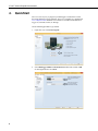
1. Open Short Cut. Click New Program.
2. Select Datalogger Model and Scan Interval (default of 5 seconds is OK
for most applications). Click Next.

27106T Vertical Propeller Anemometer
3
3. Under the Available Sensors and Devices list, select the Sensors |
Meteorological | Wind Speed & Direction folder. Select 27106T Wind
Speed Sensor and click to move the selection to the selected device
window. The units default to meters/second, which can be changed by
clicking the Wind Speed box and selecting one of the other options.
4. After selecting the sensor, click Wiring Diagram to see how the sensor is
to be wired to the datalogger. The wiring diagram can be printed now or
after more sensors are added.

27106T Vertical Propeller Anemometer
4
5. Select any other sensors you have, then finish the remaining Short Cut
steps to complete the program. The remaining steps are outlined in Short
Cut Help, which is accessed by clicking on Help | Contents |
Programming Steps.
6. If LoggerNet, PC400, RTDAQ, or PC200W is running on your PC, and the
PC to datalogger connection is active, you can click Finish in Short Cut
and you will be prompted to send the program just created to the
datalogger.
7. If the sensor is connected to the datalogger, as shown in the wiring
diagram in step 4, check the output of the sensor in the datalogger support
software data display to make sure it is making reasonable measurements.
5. Overview
The 27106T measures air velocity using a fast-response, four-blade helicoid
propeller that drives a high quality tech-generator transducer. The transducer
converts the propeller’s rotation to a dc voltage that is linearly proportional to
air velocity. The 27106T connects directly to a Campbell Scientific datalogger,
which measures the 27106T’s signal and converts the signal to engineering
units (mph, m s
-1
, knots).
The 27106T is manufactured by R.M. Young (Traverse City, MI) and cabled
by Campbell Scientific for use with our dataloggers. The R.M. Young
instruction manual includes additional information on the operating principles,
installation, and maintenance of the sensor.
6. Specifications
Features:
• Especially suited for monitoring vertical wind, but can be mounted to
monitor the wind in whatever direction is desired
• Carbon-fiber thermoplastic (CFT) propeller provides greater range
and durability than other propeller anemometers offered by R.M.
Young.
• Compatible with Campbell Scientific CRBasic dataloggers:
CR200(X) series, CR300 series, CR6 series, CR800 series, CR1000,
CR3000, CR5000, and CR9000(X)
Range
Axial Flow: 0 to 40 m/s (0 to 90 mph)
All Angles: 0 to 35 m/s (0 to 80 mph)
Threshold Sensitivity
1
: 0.4 m/s (0.8 mph)
Distance Constant
1
: <2.1 m (6.9 ft)
Pitch: 30.0 cm (11.8 in) air passage per
revolution
Signal Output: Analog dc voltage proportional to axial
wind component. Polarity reverses with
reverse rotation.
1800 rpm (500 mV) = 9.0 m/s (20.1 mph)

27106T Vertical Propeller Anemometer
5
Operating Temperature: –50 to 50 °C
Propeller Description: 4-blade helicoids propeller molded of
carbon fiber thermoplastic
Dimensions
Overall Length: 43 cm (17 in)
Propeller Diameter: 20 cm (8 in)
Housing Diameter: 2.5 cm (1 in)
1180 Mounting Pipe Description: 12-in. long, 3/4-in. IPS schedule 40 pipe
(1.05 in. OD)
Weight: 0.5 kg (1.2 lb)
1
Threshold and Distant Constant values are for axial flows.
7. Installation
If you are programming your datalogger with Short Cut, skip Section 7.3,
Wiring
(p. 7), and Section 7.4, Programming (p. 8). Short Cut does this work for
you. See Section 4, QuickStart
(p. 2), for a Short Cut tutorial.
7.1 Siting
The 27106T should be oriented with the propeller facing the predominant flow
of air being measured. No obstacle should interfere with the vertical air flow
from either the up or down direction.
The propeller responds only to the component of the air flow, which is parallel
to the axis of its rotation. Off-axis response closely approximates a cosine
curve with appropriate polarity. With perpendicular air flow, the propeller does
not rotate.
7.2 Assembly and Mounting
Tools Required:
• 1/2-inch open-end wrench for the CM220 Right-Angle Mount or 5/32-
inch Allen wrench for the 1049 NU-RAIL fitting
• UV resistant cable ties
• small pair of diagonal-cutting pliers
• 6-inch to 10-inch torpedo level
Mount the 27106T to a tripod or tower using the tools listed above:
1. Mount a Campbell Scientific crossarm to a tripod or tower.
2. Remove the nut that is on the top of the propeller shaft (FIGURE 7-1 or
FIGURE 7-2).
3. Place the propeller on top of the propeller shaft. Replace the nut and
tighten to secure the propeller to the shaft (FIGURE 7-1 or FIGURE 7-2).

27106T Vertical Propeller Anemometer
6
4. Remove the dust cap from the mating connector and mate it with the
sensor connector. The cable comes routed through the 3/4-inch IPS pipe
(pn 1180) to the mating connector.
5. Secure the pipe to the CM220 mount (FIGURE 7-1) or 1049 NU-RAIL
(FIGURE 7-2).
6. Route the sensor cable along the underside of the crossarm to the tripod or
tower, and to the instrument enclosure.
7. Secure the cable to the crossarm and tripod or tower using cable ties.
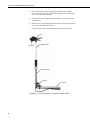
FIGURE 7-1. 27106T Mounted to a Crossarm via the CM220
Propeller Shaft
Nut
Mounting Pipe
CM220
Crossarm
Propeller
Cable Tie

27106T Vertical Propeller Anemometer
7
FIGURE 7-2. 27106T Mounted to a Crossarm via a NU-RAIL Fitting
7.3 Wiring
Connections to Campbell Scientific dataloggers are given in TABLE 7-1.
TABLE 7-1. Wire Color, Wire Function, and Datalogger Connection
Wire Color Wire Function Datalogger Connection Terminal
White Signal
U configured for single-ended analog
input
1
, SE (single-ended, analog-
voltage input)
Black Signal Reference
⏚
(analog ground)
Clear Shield
⏚
(analog ground)
1
U channels are automatically configured by the measurement instruction.
Propeller Shaft
Nut
Mounting Pipe
NU-RAIL Fitting
Crossarm
Propeller
Cable Tie

27106T Vertical Propeller Anemometer
8
7.4 Programming
Short Cut is the best source for up-to-date datalogger programming code.
Programming code is needed when:
• Creating a program for a new datalogger installation
• Adding sensors to an existing datalogger program
If your data acquisition requirements are simple, you can probably create and
maintain a datalogger program exclusively with Short Cut. If your data
acquisition needs are more complex, the files that Short Cut creates are a great
source for programming code to start a new program or add to an existing
custom program.
Short Cut cannot edit programs after they are imported and edited
in CRBasic Editor.
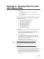
A Short Cut tutorial is available in Section 4, QuickStart (p. 2). If you wish to
import Short Cut code into CRBasic Editor to create or add to a customized
program, follow the procedure in Appendix A, Importing Short Cut Code Into
CRBasic Editor
(p. A-1). Programming basics for CRBasic dataloggers are in the
following section. Complete program examples for select CRBasic dataloggers
can be found in Appendix B, Example Program
(p. B-1). Programming basics
and programming examples for Edlog dataloggers are provided at
www.campbellsci.com\old-manuals.
7.4.1 VoltSE Instruction
The VoltSE() measurement instruction programs the datalogger to measure the
27106T.
VoltSE( Dest, Reps, Range, SEChan, MeasOff, SettlingTime,
Integ/f
notch
, Mult, Offset )
For Range, use mV2500 (CR300, CR1000) or mV5000 (CR3000, CR5000). If
the anemometer will be in electrically noisy environments, use 50 Hz or 60 Hz
rejection for Integ/f
notch
.
7.4.2 Multiplier and Offset
The expression for wind speed (U) is:
U = MX + B
Where,
M = multiplier
X = voltage measured by the datalogger
B = offset
TABLE 7-2 lists the multipliers to obtain miles/hour, meters/second, km/H,
and knots. The helicoid propeller has a calibration that passes through zero, so
the offset is zero.
NOTE

27106T Vertical Propeller Anemometer
9
TABLE 7-2. Wind Speed Multiplier
1
Unit Multiplier
Miles per Hour 0.04025
Meters/Second 0.01800
Kilometers/Hour 0.06480
Knots 0.03496
1
When the propeller is used for measuring the vertical wind component, users may
want to apply an additional multiplier of 1.25 to the output signal. This may be done
numerically in the data processing operations or electronically in the signal
conditioning. Using the additional multiplier brings the anemometer output signal
within ±3% of the cosine response for elevation angles between –30° and 30°. Since
the standard deviation of wind elevation angle in open terrain rarely exceeds 12°,
98% (2.5 standard deviations) of observations will be within ±30°. Using the
multiplier is not necessary when the anemometer is used in a UVW configuration
with R.M. Young model 26601UVW Translator.
8. Maintenance and Troubleshooting
All factory repairs and replacements require a returned material
authorization (RMA) and completion of the “Declaration of
Hazardous Material and Decontamination” form. Refer to the
Assistance page at the beginning of this manual for more
information.
8.1 Maintenance
Given proper care, the 27106T should provide years of service. Components
are conservatively rated and require little maintenance. The only parts likely to
need replacement due to normal wear are the precision ball bearings and the
tach-generator.
Campbell Scientific recommends returning the sensor to the
factory and having our qualified technicians replace the
bearings and tach-generator. When available, a qualified
technician can replace the bearings and/or generator by
following the procedures included in this document. These
replacement procedures are from R.M. Young 27106T
Operational Manual.
8.1.1 Flange Bearing Replacement
If anemometer bearings become noisy or wind speed threshold increases above
an acceptable level, bearings may need replacement. You can check bearing
condition using a Model 18310 Anemometer Bearing Torque Disk (available
from R.M. Young). If, after replacing bearings, the torque is still too high,
check the tach-generator.
NOTE
CAUTION

27106T Vertical Propeller Anemometer
10
If the bearings need to be replaced, have either Campbell Scientific or a
qualified technician replace them by using the following procedure:
1. Remove old bearings:
a. Remove propeller from anemometer.
b. Unthread and separate shaft housing assembly from generator
housing.
c. Loosen set screw on shaft collar/coupling disk and remove from
propeller shaft.
d. Slide propeller shaft through both bearings and out of housing.
e. Pull front bearing dust shield off housing.
f. Using the edge of a pocket knife, gently pry front and rear bearings
out of housing.
2. Install new bearings:
a. Gently insert front bearing into housing.
b. Push front bearing dust shield back onto housing.
c. Carefully slide propeller shaft through front bearing and into housing.
d. Slide rear bearing over propeller shaft and gently push it into housing.
e. Place shaft collar/coupling disk on propeller shaft.
f. Allow 0.010 inch (0.25 mm) end play gap between shaft
collar/coupling disk and bearing. Tighten set screw (80 oz in, 5600
gm-cm max torque).
g. Thread shaft housing assembly into generator housing. Tighten firmly.
h. Check bearing torque to confirm it is within specifications.
8.1.2 Tach-Generator Replacement
When the tach-generator output becomes erratic (usually due to brush failure)
or begins to show signs of bearing failure (high torque), the entire generator
assembly should be removed and replaced. Before replacing the tach-generator
due to excessive torque, ensure it is caused by a worn tach-generator, and not
the anemometer flange bearings.
If the tach-generator needs to be replaced, have either Campbell Scientific or a
qualified technician replace it by using the following procedure:
1. Remove old generator assembly:
a. Remove propeller from anemometer.

27106T Vertical Propeller Anemometer
11
b. Unthread generator housing collar. Pull generator housing away from
sensor connector and generator assembly.
c. Note position of generator wires on sensor connector pins. Unsolder
wires from pins and remove old generator assembly.
2. Install new generator assembly:
a. Solder wires from new generator assembly onto proper sensor
connector pins. Verify correct polarity; CCW rotation produces
negative output voltage.
b. Slide generator housing over generator assembly. Firmly tighten
housing collar onto connector threads.
c. Check bearing torque to confirm it is within specification.
8.2 Troubleshooting
Symptom: No wind speed
1. Check that the sensor is wired to the single-ended channel specified by the
VoltSE instruction.
2. Disconnect the sensor from the datalogger and use an ohm meter to check
the tach-generator. The resistance between the white and black wires
should be about 32 Ω. Infinite resistance indicates an open coil; low
resistance indicates a shorted coil.
3. Verify that the Range parameter for the VoltSE instruction is correct for
the datalogger type.
9. References
References containing additional information about the 207106T are listed
below in chronological order.
Holmes, R.M., Gill, G.C., and Carson, H.W., “A Propeller Type Vertical
Anemometer”, Journal of Applied Meteorology, Vol 3, 1964, pp. 802-804
Drinkow, R., “A Solution to the Paired Gill-Anemometer Response Function”,
Journal of Applied Meteorology, Vol 11, 1972, pp. 7-80.
Hicks, B. B., “Propeller Anemometers as Sensors of Atmospheric Turbulence”,
Boundary-Layer Meteorology, Vol 3, 1972, pp. 214-228
Fichtl, G. H., and Kumar, P., “The Response of Propeller Anemometer to
Turbulent Flow with the Mean Wind Vector Perpendicular to the Axis of
Rotation”, Boundary-Layer Meteorology, Vol 6, 1974, pp. 363-379.
McMichael, J.M., and Klebanoff, P. S., “The Dynamic Response of Helicoid
Anemometers”, NBSIR 75-772, National Bureau of Standards, 1975.
R.M Young Model 27106 Gill Propeller Anemometer Manual PN: 27106-90,
Rev: D030106

27106T Vertical Propeller Anemometer
12
Page is loading ...
Page is loading ...
Page is loading ...
Page is loading ...
Page is loading ...
Page is loading ...
-
 1
1
-
 2
2
-
 3
3
-
 4
4
-
 5
5
-
 6
6
-
 7
7
-
 8
8
-
 9
9
-
 10
10
-
 11
11
-
 12
12
-
 13
13
-
 14
14
-
 15
15
-
 16
16
-
 17
17
-
 18
18
-
 19
19
-
 20
20
-
 21
21
-
 22
22
-
 23
23
-
 24
24
-
 25
25
-
 26
26


Campbell Scientific 27106T Owner's manual
- Category
- Measuring, testing & control
- Type
- Owner's manual
Ask a question and I''ll find the answer in the document
Finding information in a document is now easier with AI
Related papers
-
Campbell Scientific 05103, 05108, 05108-45, and 05305 Wind Monitors Owner's manual
-
-
-
-
-
-
-
-
-
Other documents
-
 SEAV LG 2183 GB User guide
-
CMA ML90s User guide
-
AcuRite Wind Cup Assembly for 5-in-1 Weather Sensor User manual
-
Campbell HMP60 User manual
-
 Nature Power 70500 Owner's manual
-
Hummer HUMMER-10KW User manual
-
Gill 1086-PS-0050 User manual
-
Biral Thies 3D Ultrasonic Anemometer Owner's manual
-
Kondator 435-4491 Datasheet
-
Vaisala WAA252 User manual

