Page is loading ...

MuMaker-PFM-M487KM
APR 30, 2020 Page 1 of 44 Rev 1.00
NUMAKER-PFM-M487KM USER MANUAL
Maker Nu-mbed NUC472 User Manual
ARM® Cortex®- M
32-bit Microcontroller
NuMaker-PFM-M487KM
User Manual
NuMicro® M480 Series
The information described in this document is the exclusive intellectual property of
Nuvoton Technology Corporation and shall not be reproduced without permission from Nuvoton.
Nuvoton is providing this document only for reference purposes of NuMicro microcontroller based system
design. Nuvoton assumes no responsibility for errors or omissions.
All data and specifications are subject to change without notice.
For additional information or questions, please contact: Nuvoton Technology Corporation.
www.nuvoton.com

MuMaker-PFM-M487KM
APR 30, 2020 Page 2 of 44 Rev 1.00
NUMAKER-PFM-M487KM USER MANUAL
Maker Nu-mbed NUC472 User Manual
Table of Contents
1 Overview ............................................................................................. 6
M487 Series MCU Features ......................................................................... 6 1.1
NuMaker-PFM-M487KM Board Features .......................................................... 7 1.2
2 NuMaker-PFM-M487KM Board Overview ...................................................... 8
Front View ............................................................................................... 8 2.1
Rear View ............................................................................................... 9 2.2
Arduino UNO Compatible Interface ................................................................ 10
2.3
Pin Assignment for Extended Connectors ........................................................ 12 2.4
System Configuration ................................................................................ 17 2.5
2.5.1 5V Power Source ............................................................................................. 17
2.5.2 3.3V Power Source ........................................................................................... 17
2.5.3 USB Connectors .............................................................................................. 18
2.5.4 Ethernet Connectors ......................................................................................... 18
2.5.5 Arduino UNO Compatible Interface Connectors ......................................................... 18
2.5.6 Extended Connectors ........................................................................................ 18
2.5.7 Phone Jack .................................................................................................... 18
2.5.8 MicroSD Card Slot ............................................................................................ 18
2.5.9 Push-Buttons .................................................................................................. 18
2.5.10 LEDs ............................................................................................................ 18
2.5.11 Heartbeat Sensor Pads ...................................................................................... 18
2.5.12 Power Connectors ............................................................................................ 18
Audio .................................................................................................... 19 2.6
Heartbeat Sensor ..................................................................................... 20 2.7
Nu-Link2-Me ........................................................................................... 22 2.8
PCB Placement ....................................................................................... 23 2.9
3 Quick Start ........................................................................................ 24
Toolchains Supporting ............................................................................... 24 3.1
Nuvoton Nu-Link Driver Installation ................................................................ 24 3.2
BSP Firmware Download ............................................................................ 26 3.3
Hardware Setup ....................................................................................... 26 3.4
Find the Example Project ............................................................................ 28 3.5
Execute the Project under Toolchains ............................................................. 28 3.6
3.6.1 Keil MDK ....................................................................................................... 28

MuMaker-PFM-M487KM
APR 30, 2020 Page 3 of 44 Rev 1.00
NUMAKER-PFM-M487KM USER MANUAL
Maker Nu-mbed NUC472 User Manual
3.6.2 IAR EWARM ................................................................................................... 32
3.6.3 NuEclipse ...................................................................................................... 33
4 NuMaker-PFM-M487KM Schematics ......................................................... 34
Nu-Link2-Me ........................................................................................... 34 4.1
M487KMCAN .......................................................................................... 35 4.2
Power Supply .......................................................................................... 36 4.3
Arduino UNO Compatible Interface ................................................................ 37 4.4
MicroSD Card ......................................................................................... 38 4.5
USB 2.0 HS OTG and USB 1.1 FS OTG ......................................................... 39 4.6
Ethernet ................................................................................................ 40 4.7
24-bit Stereo Audio Codec .......................................................................... 41 4.8
Heartbeat Sensor ..................................................................................... 42 4.9
5 REVISION HISTORY ............................................................................ 43

MuMaker-PFM-M487KM
APR 30, 2020 Page 4 of 44 Rev 1.00
NUMAKER-PFM-M487KM USER MANUAL
Maker Nu-mbed NUC472 User Manual
List of Figures
Figure 1-1 NuMaker-PFM-M487KM Board ...................................................................................... 6
Figure 2-1 Front View of NuMaker-PFM-M487KM Board ................................................................ 8
Figure 2-2 Rear View of NuMaker-PFM-M487KM Board ................................................................ 9
Figure 2-3 Arduino UNO Compatible Interface .............................................................................. 10
Figure 2-4 NuMaker-PFM-M487KMCAN Extended Connectors ................................................... 12
Figure 2-5 3.5mm Phone Jack Diagram ........................................................................................ 19
Figure 2-6 Heartbeat Sensor Block Diagram ................................................................................. 20
Figure 2-7 Front Placement ........................................................................................................... 23
Figure 2-8 Rear Placement ............................................................................................................ 23
Figure 3-1 Nu-Link USB Driver Installation Setup .......................................................................... 24
Figure 3-2 Nu-Link USB Driver Installation .................................................................................... 25
Figure 3-3 Open VCOM Function .................................................................................................. 26
Figure 3-4 ICE USB Connector ...................................................................................................... 26
Figure 3-5 Device Manger .............................................................................................................. 27
Figure 3-6 PuTTY Session Setting................................................................................................. 27
Figure 3-7 Template Project Folder Path ....................................................................................... 28
Figure 3-8 Warning Message of “Device not found” ...................................................................... 28
Figure 3-9 Project File Migrate to Version 5 Format ...................................................................... 29
Figure 3-10 Debugger Setting in Options Window......................................................................... 29
Figure 3-11 Programming Setting in Options Window ................................................................... 30
Figure 3-12 Compile and Download the Project ............................................................................ 30
Figure 3-13 Keil MDK Debug Mode ............................................................................................... 31
Figure 3-14 Debug Message on Serial Port Terminal Windows .................................................... 31
Figure 3-15 IAR EWARM Window ................................................................................................. 32
Figure 3-16 Compile and Download the Project ............................................................................ 32
Figure 3-17 IAR EWARM Debug Mode ......................................................................................... 33
Figure 3-18 Debug Message on Serial Port Terminal Windows .................................................... 33
Figure 4-1 Nu-Link2-Me Circuit ...................................................................................................... 34
Figure 4-2 M487KMCAN Pin Assignment ...................................................................................... 35
Figure 4-3 Power Circuit and Configurations ................................................................................. 36
Figure 4-4 Arduino UNO Compatible Interface .............................................................................. 37
Figure 4-5 MicroSD Card Circuit .................................................................................................... 38
Figure 4-6 USB HS OTG and FS OTG Circuits ............................................................................. 39
Figure 4-7 Ethernet Circuit ............................................................................................................. 40
Figure 4-8 Audio Codec Circuit ...................................................................................................... 41
Figure 4-9 Heartbeat Sensor Circuits ............................................................................................ 42

MuMaker-PFM-M487KM
APR 30, 2020 Page 5 of 44 Rev 1.00
NUMAKER-PFM-M487KM USER MANUAL
Maker Nu-mbed NUC472 User Manual
List of Tables
Table 2-1 Arduino UNO Interface Mapping with M487KMCAN GPIO ........................................... 11
Table 2-2 Extended Connector JP6 Interface with M487KMCAN GPIO ....................................... 13
Table 2-3 Extended Connector JP8 Interface with M487KMCAN GPIO ....................................... 14
Table 2-4 Extended Connector JP7 Interface with M487KMCAN GPIO ....................................... 15
Table 2-5 Extended Connector JP9 Interface with M487KMCAN GPIO ....................................... 16
Table 2-6 NAU88L25 Mapping with NuMaker-PFM-M487KMCAN ............................................... 19
Table 2-7 Pin Usage of Heartbeat Sensor ..................................................................................... 21
Table 2-8 ICESW2 VCOM function ................................................................................................ 22

MuMaker-PFM-M487KM
APR 30, 2020 Page 6 of 44 Rev 1.00
NUMAKER-PFM-M487KM USER MANUAL
Maker Nu-mbed NUC472 User Manual
1 OVERVIEW
This user manual is aimed to give users a fast introduction to the use of NuMaker-PFM-M487KM
board.
The NuMaker-PFM-M487KM consists of two parts, a M487KM platform and an on-board Nu-Link2-Me
debugger and programmer. The NuMaker-PFM-M487KM allows users to quickly develop and easily
program and debug application.
The NuMaker-PFM-M487KM offers M487KMCAN full pins extension connectors and Arduino UNO
compatible extension connectors. It is an easy-to-develop platform for user to expand the functionality
and build the applications. The NuMaker-PFM-M487KM also provides an ammeter connector, allows
user to monitor the microcontroller’s power consumption during development.
The Nu-Link2-Me is a debugger and programmer that supports on-line programming and debugging
through SWD interface. The on-board 16 Mbit SPI Flash allows it able to off-line programming the
target microcontroller. Nu-Link2-Me provides virtual COM port (VCOM) function to print out messages
on PC. Nu-Link2-Me can be separated from NuMaker-PFM-M487KM, allowing user to use as a mass
production programming tool.
Figure 1-1 NuMaker-PFM-M487KM Board
M487 Series MCU Features 1.1
M487KMCAN in LQFP128 package
ARM® Cortex®-M4 core running up to 192 MHz with DSP extensions and FPU (Floating
Point Unit)
2560 Kbytes Flash
160 Kbytes SRAM
External Bus Interface (EBI)
GPIO
Peripheral DMA (PDMA)
Timer
PWM and BPWM

MuMaker-PFM-M487KM
APR 30, 2020 Page 7 of 44 Rev 1.00
NUMAKER-PFM-M487KM USER MANUAL
Maker Nu-mbed NUC472 User Manual
Quadrature Encoder Interface (QEI)
WDT and WWDT
RTC
UART
Smart Card (ISO-7816-3) Host Interface
I2C
SPI
SPIM
I2S
Universal Serial Control Interface (USCI)
USB 2.0 High-Speed OTG / Host / Device
USB 1.1 Full-Speed OTG / Host / Device
CAN 2.0
Ethernet MAC
SD Host
Cryptographic Accelerator
CRC
ADC
DAC
Comparator
NuMaker-PFM-M487KM Board Features 1.2
On-board Nu-Link2-Me debugger and programmer:
Debug through SWD interface
On-line/off-line programming
Virtual COM port function
Arduino UNO compatible interface
M487 extended interface connectors
Audio codec (NAU88L25) with Microphone In and Headphone Out
Ethernet for network application
USB 2.0 High-Speed OTG / Host / Device
USB 1.1 Full-Speed OTG / Host / Device
External SPI Flash which can be regarded as ROM module
MicroSD Card slot for T-Flash
Three push-buttons: one is for reset and the other two are for user-defined
Four LEDs: one is for power indication and the other two are for user-defined

MuMaker-PFM-M487KM
APR 30, 2020 Page 8 of 44 Rev 1.00
NUMAKER-PFM-M487KM USER MANUAL
Maker Nu-mbed NUC472 User Manual
2 NUMAKER-PFM-M487KM BOARD OVERVIEW
Front View 2.1
Figure 2-1 shows the main components and connectors from the front side of NuMaker-PFM-M487KM
board.
The following lists components and connectors from the front view:
Target Chip: M487KMCAN (U1)
Audio: Audio Codec NAU88L25 (U8), Headphone (CN2)
Arduino UNO compatible interface connectors (NU1, NU2, NU3, NU4 and NU5)
M487 extended interface connectors (JP6, JP7, JP8 and JP9)
USB: USB 2.0 High-Speed OTG connector (CON1) and USB 1.1 OTG connector (CON2)
Ethernet Transceivers: IP101GR (U5)
Push-buttons (SW2, SW3)
LEDs (LEDR and LEDG)
Nu-Link2-Me
VCOM Switch
ICE Chip: M48SSIDAE(ICEU1)
ICE USB Connector(ICEJ3)
ICE Status LED(ICES0,ICES1, ICES2, ICES3)
Off-line Program Button(ICESW1)
Figure 2-1 Front View of NuMaker-PFM-M487KM Board

MuMaker-PFM-M487KM
APR 30, 2020 Page 9 of 44 Rev 1.00
NUMAKER-PFM-M487KM USER MANUAL
Maker Nu-mbed NUC472 User Manual
Rear View 2.2
Figure 2-2 shows the main components and connectors from the rear side of NuMaker-PFM-M487KM
board.
The following lists components and connectors from the rear view:
MicroSD Card Slot: T-Flash slot (U9)
Nu-Link2-Me
MCUVCC Power Switch (ICEJPR1)
ICEVCC Power Switch (ICEJPR2)
Figure 2-2 Rear View of NuMaker-PFM-M487KM Board


MuMaker-PFM-M487KM
APR 30, 2020 Page 11 of 44 Rev 1.00
NUMAKER-PFM-M487KM USER MANUAL
Maker Nu-mbed NUC472 User Manual
Table 2-1 Arduino UNO Interface Mapping with M487KMCAN GPIO
Header
NuMaker-PFM-M487KM
Header
NuMaker-PFM-M487KM
Compatible to
Arduino UNO
GPIO Pin of M487
Compatible to
Arduino UNO
GPIO Pin of M487
N
U
1
NU1.1
NC
-
N
U
4
NU4.10
SCL
PC.5
NU1.2
IOREF
NU4.9
SDA
PC.4
NU1.3
RESET
RESET
NU4.8
VREF
-
NU1.4
3VCC
-
NU4.7
GND
NU1.5
5VCC
NU4.6
D13
PA.2
NU1.6
GND
NU4.5
D12
PA.1
NU1.7
GND
NU4.4
D11
PA.0
NU1.8
VIN
NU4.3
D10
PA.3
N
U
2
NU2.1
A0
PB.6
NU4.2
D9
PA.4
NU2.2
A1
PB.7
NU4.1
D8
PE.15
NU2.3
A2
PB.8
N
U
3
NU3.8
D7
PE.5
NU2.4
A3
PB.9
NU3.7
D6
PE.3
NU2.5
A4
PB.0
NU3.6
D5
PC.12
NU2.6
A5
PB.1
NU3.5
D4
PC.11
NU3.4
D3
PC.10
NU3.3
D2
PC.9
NU3.2
D1
PB.3
NU3.1
D0
PB.2
Header
NuMaker-PFM-M487KM
Header
NuMaker-PFM-M487KM
Compatible to
Arduino UNO
GPIO Pin of M487
Compatible to
Arduino UNO
GPIO Pin of M487
N
U
5
NU5.1
MISO
PG.4
N
U
5
NU5.2
VCC
-
NU5.3
CLK
PA.10
NU5.4
MOSI
PA.8
NU5.5
NC
-
NU5.6
GND
-
NU5.7
SS
PA.11
NU5.8
NC
-

MuMaker-PFM-M487KM
APR 30, 2020 Page 12 of 44 Rev 1.00
NUMAKER-PFM-M487KM USER MANUAL
Maker Nu-mbed NUC472 User Manual
Pin Assignment for Extended Connectors 2.4
The NuMaker-PFM-M487KM provides the M487KMCAN target chip onboard and extended
connectors (JP6, JP7, JP8 and JP9) for LQFP128-pin. The Figure 2-4 shows the NuMaker-PFM-
M487KMCAN extended connectors.
Figure 2-4 NuMaker-PFM-M487KMCAN Extended Connectors

MuMaker-PFM-M487KM
APR 30, 2020 Page 13 of 44 Rev 1.00
NUMAKER-PFM-M487KM USER MANUAL
Maker Nu-mbed NUC472 User Manual
Table 2-2 Extended Connector JP6 Interface with M487KMCAN GPIO
Header
NuMaker-PFM-M487KM
Header
NuMaker-PFM-M487KM
Pin No.
Function
Pin No
Function
JP6
JP6.1
1
PB.5
JP6
JP6.2
2
PB.4
JP6.3
3
PB.3
JP6.4
4
OPA0_O
JP6.5
5
PC.12
JP6.6
6
PC.11
JP6.7
7
PC.10
JP6.8
8
PC.9
JP6.9
9
OPA0_N
JP6.10
10
OPA0_P
JP6.11
11
GND
JP6.12
12
3VCC
JP6.13
13
PA.11
JP6.14
14
OPA1_O
JP6.15
15
OPA1_N
JP6.16
16
OPA1_P
JP6.17
17
JKDET
JP6.18
18
OPA2_O
JP6.19
19
OPA2_N
JP6.20
20
OPA2_P
JP6.21
21
PG.2
JP6.22
22
PG.3
JP6.23
23
PG.4
JP6.24
24
SW3
JP6.25
25
I2S0_BCLK
JP6.26
26
I2S0_MCLK
JP6.27
27
I2S0_DI
JP6.28
28
I2S0_DO
JP6.29
29
I2S0_LRCK
JP6.30
30
3VCC
JP6.31
31
XT32_IN
JP6.32
32
XT32_OUT

MuMaker-PFM-M487KM
APR 30, 2020 Page 14 of 44 Rev 1.00
NUMAKER-PFM-M487KM USER MANUAL
Maker Nu-mbed NUC472 User Manual
Table 2-3 Extended Connector JP8 Interface with M487KMCAN GPIO
Header
NuMaker-PFM-M487KM
Header
NuMaker-PFM-M487KM
Pin No.
Function
Pin No
Function
JP7
JP7.1
33
LED_R
JP7
JP7.2
34
LED_G
JP7.3
35
PH.6
JP7.4
36
PH.7
JP7.5
37
XT1_IN
JP7.6
38
XT1_OUT
JP7.7
39
GND
JP7.8
40
3VCC
JP7.9
41
EMAC_MDC
JP7.10
42
EMAC_MDIO
JP7.11
43
EMAC_TXD0
JP7.12
44
EMAC_TXD1
JP7.13
45
EMAC_TXEN
JP7.14
46
JKEN#
JP7.15
47
EMAC_REFCLK
JP7.16
48
EMAC_RXD0
JP7.17
49
EMCAC_RXD1
JP7.18
50
EMAC_RXDV
JP7.19
51
EMAC_RXERR
JP7.20
52
GND
JP7.21
53
3VCC
JP7.22
54
LDO_CAP
JP7.23
55
SD1_CMD
JP7.24
56
PA.4
JP7.25
57
PA.3
JP7.26
58
PA.2
JP7.27
59
PA.1
JP7.28
60
PA.0
JP7.29
61
VDDIO
JP7.30
62
SD1_nCD
JP7.31
63
PE.15
JP7.32
64
nRESET

MuMaker-PFM-M487KM
APR 30, 2020 Page 15 of 44 Rev 1.00
NUMAKER-PFM-M487KM USER MANUAL
Maker Nu-mbed NUC472 User Manual
Table 2-4 Extended Connector JP7 Interface with M487KMCAN GPIO
Header
NuMaker-PFM-M487KM
Header
NuMaker-PFM-M487KM
Pin No.
Function
Pin No
Function
JP8
JP8.1
65
ICEDAT
JP8
JP8.2
66
ICECLK
JP8.3
67
I2C2_SCL
JP8.4
68
I2C2_SDA
JP8.5
69
I2C1_SCL
JP8.6
70
I2C1_SDA
JP8.7
71
PC.3
JP8.8
72
PC.2
JP8.9
73
PC.1
JP8.10
74
PC.0
JP8.11
75
GND
JP8.12
76
3VCC
JP8.13
77
SD1_DAT3
JP8.14
78
SD1_DAT2
JP8.15
79
NC
JP8.16
80
SD1_DAT0
JP8.17
81
NC
JP8.18
82
SD1_CLK
JP8.19
83
SW2
JP8.20
84
PD.13
JP8.21
85
USB_VBUS
JP8.22
86
USB_D-
JP8.23
87
USB_D+
JP8.24
88
USB_ID
JP8.25
89
HSUSB_VRES
JP8.26
90
HSUSB_VDD33
JP8.27
91
HSUSB_VBUS
JP8.28
92
HSUSB_D-
JP8.29
93
HSUSB_VSS
JP8.30
94
HSUSB_D+
JP8.31
95
HSUSB_VDD12_CAP
JP8.32
96
HSUSB_ID

MuMaker-PFM-M487KM
APR 30, 2020 Page 16 of 44 Rev 1.00
NUMAKER-PFM-M487KM USER MANUAL
Maker Nu-mbed NUC472 User Manual
Table 2-5 Extended Connector JP9 Interface with M487KMCAN GPIO
Header
NuMaker-PFM-M487KM
Header
NuMaker-PFM-M487KM
Pin No.
Pin Name
Pin No
Pin Name
JP9
JP9.1
97
NC
JP9
JP9.2
98
NC
JP9.3
99
PE.5
JP9.4
100
NC
JP9.5
101
PE.3
JP9.6
102
NC
JP9.7
103
GND
JP9.8
104
3VCC
JP9.9
105
PE.1
JP9.10
106
PE.0
JP9.11
107
PH.8
JP9.12
108
PH.9
JP9.13
109
PH.10
JP9.14
110
PH.11
JP9.15
111
PD.14
JP9.16
112
GND
JP9.17
113
LDO_CAP
JP9.18
114
3VCC
JP9.19
115
USB_VBUS_ST
JP9.20
116
USB_VBUS_EN
JP9.21
117
EADC0_CH14
JP9.22
118
TXD
JP9.23
119
RXD
JP9.24
120
AVDD
JP9.25
121
VREF
JP9.26
122
ADAVSS
JP9.27
123
HSUSB_VBUS_ST
JP9.28
124
HSUSB_VBUS_EN
JP9.29
125
PB.9
JP9.30
126
PB.8
JP9.31
127
PB.7
JP9.32
128
PB.6

MuMaker-PFM-M487KM
APR 30, 2020 Page 17 of 44 Rev 1.00
NUMAKER-PFM-M487KM USER MANUAL
Maker Nu-mbed NUC472 User Manual
System Configuration 2.5 2.5.1 5V Power Source
ICEJ: USB connector in Nu-Link-Me to program code and supplies 5V power from PC
Host.
CON1: USB 2.0 High-Speed OTG connector on NuMaker-PFM-M487KM board to supply
5V power from PC Host when this USB is a device that be decided by the ID pin of OTG
cable and this ID pin is low.
CON2: USB 1.1 OTG connector on NuMaker-PFM-M487KM board to supply 5V power
from PC Host when this USB is a device that be decided by the ID pin of OTG cable and
this ID pin is low.
NU1 pin5: VDD5V voltage connector on NuMaker-PFM-M487KM board to supply 5V
power from external power source.
Power
Source
Connector
Comment
ICE_USB_VBUS
ICEJ3
ICEJ supplies the 5V power from PC Host.
Note: L2 should be shorted 0ohm
HSUSB_VBUS
CON1
CON1 supplies the 5V power from PC Host.
Note: L11 should be shorted 0ohm.
USB_VBUS
CON2
CON2 supplies the 5V power from PC Host.
Note: L12 should be shorted 0ohm.
External 5V Source
NU1 pin5
NU1 pin5 supplies the 5V power from external power source.
Note: L10 should be shorted 0ohm.
2.5.2 3.3V Power Source
ICEUP1: The voltage regular converts the 5V source to 3.3V and supplies it to NuMaker-
PFM-M487KM board.
U4: The voltage regular converts the 5V source to 3.3V and supplies it to NuMaker-PFM-
M487KM board.
Voltage
Regular
5V
Source
Comment
ICEUP1
ICE_USB_VBUS
ICEU1 convert ICE_USB_VBUS to 3.3V and supplies it to
M487 platform board.
Note: L4 should be shorted 0ohm
U4
HSUSB_VBUS
U4 convert HSUSB_VBUS to 3.3V and supplies it to M487
platform board.
Note: L5 should be shorted 0ohm.
U4
USB_VBUS
U4 convert USB_VBUS to 3.3V and supplies it to M487
platform board.
Note: L5 should be shorted 0ohm.

MuMaker-PFM-M487KM
APR 30, 2020 Page 18 of 44 Rev 1.00
NUMAKER-PFM-M487KM USER MANUAL
Maker Nu-mbed NUC472 User Manual
2.5.3 USB Connectors
ICEJ3: USB connector (ICE) in Nu-Link-Me that connects to a PC’s USB Host port to
program code and supply power.
CON1: USB 2.0 High-Speed connector (OTG) on NuMaker-PFM-M487KM board for USB
OTG application use.
CON2: USB 1.1 connector (OTG) on NuMaker-PFM-M487KM board for USB OTG
application use.
2.5.4 Ethernet Connectors
CN1: Ethernet connector (RJ-45) on NuMaker-PFM-M487KM board for application use.
2.5.5 Arduino UNO Compatible Interface Connectors
NU1, NU2, NU3, NU3 and NU5: Arduino UNO compatible pins on the NuMaker-PFM-
M487KM board.
2.5.6 Extended Connectors
JP6, JP7, JP8 and JP9: Extended connectors interface pins on the NuMaker-PFM-
M487KM board.
2.5.7 Phone Jack
CN2: Phone jack connector on NuMaker-PFM-M487KM for audio application use.
2.5.8 MicroSD Card Slot
U9: MicroSD card slot for application use.
2.5.9 Push-Buttons
SW1: Reset button to reset the target chip on NuMaker-PFM-M487KM board.
SW2, SW3: Only for application use.
2.5.10 LEDs
POWER: The power LED indicates that the NuMaker-PFM-M487KM board is powered.
I/O1, I/O2 and I/O3: Only for application use.
2.5.11 Heartbeat Sensor Pads
Heartbeat L: The heartbeat sensor pad on the left hand.
Heartbeat R: The heartbeat sensor pad on the right hand.
2.5.12 Power Connectors
JP2, JP3: 3VCC connectors on the NuMaker-PFM-M487KM board.
JP4, JP5, JP10 and JP11: GND connectors on the NuMaker-PFM-M487KM board.

MuMaker-PFM-M487KM
APR 30, 2020 Page 19 of 44 Rev 1.00
NUMAKER-PFM-M487KM USER MANUAL
Maker Nu-mbed NUC472 User Manual
Audio 2.6
NuMaker-PFM-M487KM features a Nuvoton NAU88L25 audio codec which is an ultra-low power high
performance audio codec designed for headphone or headset application. It includes one I2S/PCM
interface, one high quality stereo DACs, one mono ADC, a Class G stereo headphone amplifier, and
industry leading advanced headset features.
The NAU88L25 connects to the NuMaker-PFM-M487KM via I2C bus (M487 is I2C master) for control,
the I2C address of NUA88L25 is 0x1A by default, and via I2S bus (M487 is I2S slave) for audio digital
data. The Table 2-6 shows the pin mapping between NUC88L25 and M487KMCAN.
Table 2-6 NAU88L25 Mapping with NuMaker-PFM-M487KMCAN
NuMaker-PFM-
M487KM
NAU88L25
Comment
I2C2_SCL
SCLK
I2C clock output
Note: The I2C address of NAU88L25 is 0x1A by default.
I2C2_SDA
SDIO
I2C data input/output
Note: The I2C address of NAU88L25 is 0x1A by default.
I2S0_BCLK
BCLK
I2S bit clock output from NAU88L25
I2S0_MCLK
MCLK
I2S master clock output from M487
I2S0_DI
ADCOUT
I2S data input to NAU88L25
I2S0_DO
DACIN
I2S data output from M487
I2S0_LRCK
FS
I2S left right channel clock output from NAU88L25
PC.13
JKDET
To detect phone jack insertion and ejection
PE.13
JKEN#
To control phone jack output
The 3.5mm phone jack CN2 is used to attach the headset with microphone, the Figure 2-5 shows the
phone jack diagram.
Figure 2-5 3.5mm Phone Jack Diagram

MuMaker-PFM-M487KM
APR 30, 2020 Page 20 of 44 Rev 1.00
NUMAKER-PFM-M487KM USER MANUAL
Maker Nu-mbed NUC472 User Manual
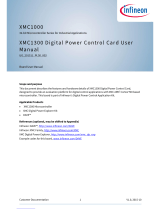
Heartbeat Sensor 2.7
NuMaker-PFM-M487KM features an on-board heartbeat sensor, it can detect the tiny electrical signal
between human’s right and left hand during each heartbeat. The tiny electrical signal passes through
three stages of operational amplifiers which are built in M487KMCAN to amplify the differential
electrical signal and filter the noise of environment. The Figure 2-6 shows the heartbeat sensor block
diagram.
Heartbeat R/L Sensor Pads
The heartbeat sensor pads are used to detect the tiny electrical signal between human’s right
and left hand during each heartbeat.
OPA0 (Differential Amplifier and Filter)
OPA0 is used to amplify the differential electrical signal between right and left sensor pads and
filter the DC bias then passes it to OPA1.
OPA1 (Bypass Filter and Input Buffer)
OPA1 is a bypass filter which is used to suppress 60Hz noise and pass the signal without the
noise to OPA2.
OPA2 (Amplifier)
OPA2 is used to amplify the signal comes from OPA1 then passes it to the ADC channel of
M487KMCAN to convert the analog signal to the digital signal.
Figure 2-6 Heartbeat Sensor Block Diagram
/