Dynisco IPX II Series User manual
- Category
- Measuring, testing & control
- Type
- User manual

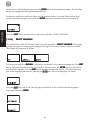
OPERATING MANUAL
IPX II SeriesIPX II Series
IPX II SeriesIPX II Series
IPX II Series
SmSm
SmSm
Smarar
arar
artt
tt
t Pr Pr
Pr Pr
Pree
ee
ess
ss
sss
ss
surur
urur
ure e
e e
e
TT
TT
Trr
rr
ranan
anan
ansmittsmitt
smittsmitt
smitterer
erer
erss
ss
s
ff
ff
for High Pror High Pr
or High Pror High Pr
or High Pree
ee
ess
ss
sss
ss
surur
urur
uree
ee
ess
ss
s and High and High
and High and High
and High TT
TT
Temperemper
emperemper
emperatat
atat
aturur
urur
uree
ee
ess
ss
s
P/N 974100
05/05 Rev. F
ECO # 29918
II 1 GII 1 G
II 1 GII 1 G
II 1 G
AA
AA
ATEX100aTEX100a
TEX100aTEX100a
TEX100a

OPERATING MANUAL

OPERATING MANUAL
TT
TT
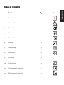
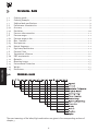
TABLEABLE
ABLEABLE
ABLE
OFOF
OFOF
OF C C
C C
C
ONTENTSONTENTS
ONTENTSONTENTS
ONTENTS
ContentContent
ContentContent
Content PP
PP
Pagag
agag
agee
ee
eIconIcon
IconIcon
Icon
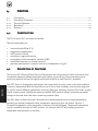
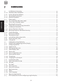
1. General 4
2. Notes on safety 6
3. Technical data 8
4. Function 22
5. Transport/delivery 26
6. Assembly 27
7. Commissioning 34
8. Maintenance 66
9. Accessories 68
10. Troubleshooting 69
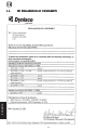
11. CE-Declaration of conformity 72
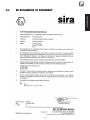
12. Ex-Declaration of conformity 73

4
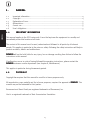
GENERAL
1.1.
1.1.
1. GG
GG
GENERALENERAL
ENERALENERAL
ENERAL
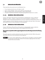
1 . 1 Important information .......................................................................................................... 4
1.2 Copyright ............................................................................................................................. 4
1.3 Explanation of icons ............................................................................................................ 5
1.4 Abbreviations....................................................................................................................... 5
1.5 Correct use .......................................................................................................................... 5
1.6 User’s obligations ................................................................................................................. 5
1.11.1
1.11.1
1.1 II
II
IMPORMPOR
MPORMPOR
MPORTT
TT
TANTANT
ANTANT
ANT
INFORMAINFORMA
INFORMAINFORMA
INFORMATIONTION
TIONTION
TION
This manual applies to the IPX II series only. It must be kept near the equipment in a readily and
immediately accessible location at all times.
The content of this manual must be read, understood and followed in all points by all relevant
people. This applies in particular to the notes on safety. Following the safety instructions will help to
prevent accidents, defects and malfunctions.
DD
DD
DYNISCYNISC
YNISCYNISC
YNISCOO
OO
O will not be held liable for any injury, loss or damage resulting from failure to follow the
instructions in this manual.
If malfunctions occur in spite of having followed the operating instructions, please contact the
DD
DD
DYNISCYNISC
YNISCYNISC
YNISCOO
OO
O customer service department (see chapter 8, Maintenance).
This applies in particular during the warranty period.
1.21.2
1.21.2
1.2 CC
CC
COPYRIGHTOPYRIGHT
OPYRIGHTOPYRIGHT
OPYRIGHT
Copyright law requires that this manual be used for in-house purposes only.
All reproduction, even partially and for in-house purposes, requires the approval of DD
DD
DYNISCYNISC
YNISCYNISC
YNISCOO
OO
O. This
manual may not be forwarded to third parties.
Rosemount and Smart Family are registered trademarks of Rosemount, Inc.
Hart is a registered trademark of Hart Comunication Foundation.

5
GENERAL
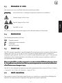
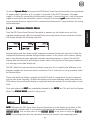
1.31.3
1.31.3
1.3 EE
EE
EXPLANAXPLANA
XPLANAXPLANA
XPLANATIONTION
TIONTION
TION
OFOF
OFOF
OF
ICIC
ICIC
ICONSONS
ONSONS
ONS
The manual uses icons to indicate information pertaining to safety:
Risk of destruction or damage to equipment, machines or installations
General danger to life or limb
Specific danger to life or limb
You MUST do this
The safety instructions are provided again in the individual chapters of the manual.
1.41.4
1.41.4
1.4 AA
AA
ABBREVIABBREVIA
BBREVIABBREVIA
BBREVIATIONSTIONS
TIONSTIONS
TIONS
The following abbreviations are used:
OMOM
OMOM
O M Operating manual
IPXIPX
IPXIPX
IPX Intelligent pressure transmitter
f.s.f.s.
f.s.f.s.
f.s. of full scale
PTPT
PTPT
PT pressure transmitter
1.51.5
1.51.5
1.5 CC
CC
CORRECTORRECT
ORRECTORRECT
ORRECT
USEUSE
USEUSE
USE
The IPX II pressure transmitter is specially designed for measuring pressure in explosive atmospheres
(safety class, EEx ia IIC T4, Ta=-20°C to +80°C) as part of a larger overall system. It contains an
integrated signal amplifier. The IPX II can be used in media temperatures up to 350°C. If the pressure
transmitter is used in other applications, the safety and accident prevention regulations specific to
that application must be followed.
When uWhen u
When uWhen u
When uss
ss
sinin
inin
ing the IPXg the IPX
g the IPXg the IPX
g the IPX II a II a
II a II a
II ass
ss
s a s a s
a s a s
a safaf
afaf
afetyety
etyety
ety c c
c c
componentomponent
omponentomponent
omponent in ac in ac
in ac in ac
in accc
cc
coror
oror
ordd
dd
dancanc
ancanc
ance we w
e we w
e with the Eith the E
ith the Eith the E
ith the ECC
CC
C M M
M M
Macac
acac
achine Dirhine Dir
hine Dirhine Dir
hine Directivectiv
ectivectiv
ective, Annee, Anne
e, Annee, Anne
e, Annexx
xx
x
IIc, the equipmentIIc, the equipment
IIc, the equipmentIIc, the equipment
IIc, the equipment m m
m m
manufanuf
anufanuf
anufactact
actact
acturur
urur
urer muer mu
er muer mu
er muss
ss
stt
tt
t t t
t t
takak
akak
ake ane an
e ane an
e anyy
yy
y nec nec
nec nec
necee
ee
ess
ss
sss
ss
sarar
arar
aryy
yy
y pr pr
pr pr
precec
ecec
ecautionaution
autionaution
autionss
ss
s t t
t t
to eno en
o eno en
o enss
ss
surur
urur
ure the th
e the th
e thatat
atat
at m m
m m
malfalf
alfalf
alfuu
uu
unctionnction
nctionnction
nctionss
ss
s
ofof
ofof
of the P the P
the P the P
the PTT
TT
Tcc
cc
cannotannot
annotannot
annot c c
c c
cauau
auau
ause dse d
se dse d
se damam
amam
amagag
agag
age or injure or injur
e or injure or injur
e or injuryy
yy
y..
..
.
The IPX II is also designed for explosion proof areas approved by factory mutual for Class I, Division
1, Groups B, C & D, Class II/III, Division 2, Group E, F & G.
1.61.6
1.61.6
1.6 UU
UU
USS
SS
SERER
ERER
ER’’
’’
’SS
SS
S
OBLIGAOBLIGA
OBLIGAOBLIGA
OBLIGATIONSTIONS
TIONSTIONS
TIONS
The operator or owner of the larger overall system, e.g. a machine, is responsible for following the
safety and accident prevention regulations that apply to the specific application.

6
SAFETY
2.2.
2.2.
2. NN
NN
NOTESOTES
OTESOTES
OTES
ONON
ONON
ON
SAFETYSAFETY
SAFETYSAFETY
SAFETY
The operator or owner of the larger overall system is responsible for following the safety
and accident prevention regulations that apply to the specific application.
TT
TT
Too
oo
oxx
xx
xicic
icic
ic h h
h h
hazaz
azaz
azarar
arar
ard!d!
d!d!
d!
The IPX II contains a small amount of mercury (Hg) as its transmission medium. If the
diaphragm is damaged, mercury may escape.
Never transport or store the IPX II without the protective cap. Remove the cap shortly
before installation.
IfIf
IfIf
If mer mer
mer mer
mercc
cc
curur
urur
uryy
yy
y i i
i i
iss
ss
s inh inh
inh inh
inhalal
alal
aled or swed or sw
ed or swed or sw
ed or swalal
alal
allolo
lolo
loww
ww
wed, seeked, seek
ed, seeked, seek
ed, seek medic medic
medic medic
medicalal
alal
al att att
att att
attention immediention immedi
ention immediention immedi
ention immediatat
atat
ately!ely!
ely!ely!
ely!
Mercury is hazardous waste and must be disposed of in accordance with applicable
laws. DD
DD
DYNISCYNISC
YNISCYNISC
YNISCOO
OO
O will accept defective PTs.
If mercury escapes, use airtight packaging!
When planning machinery and using the IPX II, follow the safety and accident
prevention regulations that apply to your application, e.g.:
• EN 60204, Electrical equipment in machines.
• EN 292, Machine safety, general design guidelines.
• DIN 57 100 Part 410, Protection against electric shock.
• EN 50 014:1997, General Requirements
• EN 50 020:1994, Intrinsic safety apparatus
• EN50284:1999, Speical requirements for Group II Category 1G
Mounting and electrical connection of the PT must be done by specialists with EMC training,
following all applicable regulations, and in pressureless, voltage-free, intrinsically safepressureless, voltage-free, intrinsically safe
pressureless, voltage-free, intrinsically safepressureless, voltage-free, intrinsically safe
pressureless, voltage-free, intrinsically safe
condition with the machine switched offmachine switched off
machine switched offmachine switched off
machine switched off.
The mThe m
The mThe m
The macac
acac
achine muhine mu
hine muhine mu
hine muss
ss
stt
tt
t be sec be sec
be sec be sec
be securur
urur
ured aged ag
ed aged ag
ed againain
ainain
ainss
ss
stt
tt
t bein bein
bein bein
being swg sw
g swg sw
g switit
itit
itcc
cc
ched bhed b
hed bhed b
hed bacac
acac
ackk
kk
k on! on!
on! on!
on!
Ambient temperature for the electronics housing mm
mm
max. +80°Cax. +80°C
ax. +80°Cax. +80°C
ax. +80°C (safety class T4 max.).
Higher temperatures can result in damage and malfunction. Do not install the pressure
transmitter in places where this temperature is exceeded.
ExpExp
ExpExp
Explolo
lolo
loss
ss
sion hion h
ion hion h
ion hazaz
azaz
azarar
arar
ard!d!
d!d!
d!
Deviation of the supply voltage from the value given in the technical specifications, or
false polarity, can damage the pressure transmitter and cause malfunctions that can
pose a risk of explosion.

7
SAFETY
Operate only with an intrinsically safe, EMC compliant power supply with the following
specifications when employing the pressure 4-20mA output:
Supply voltage max. 30 V DC
Current output max. 125 mA
Power output max. 900 mW
Inductivity max. 0.26 mH
Capacity max. 9.7 nF
Operate only with an intrinsically safe, EMC compliant power supply with the following
specifications when employing the temperature 4-20mA output:
Supply voltage max. 30 V DC
Current output max. 125 mA
Power output max. 900 mW
Inductivity max. 0 mH
Capacity max. 52 nF
For PT that are explosion proof Class I, Division 1, Groups B, C & D, Class II/III, Division
2, Groups E, F and G. Power supply rating is 12-42 Vdc.
ExpExp
ExpExp
Explolo
lolo
loss
ss
sion hion h
ion hion h
ion hazaz
azaz
azarar
arar
ard!d!
d!d!
d!
The pressure transmitter must be connected using a 2x2-core, twisted cable (blue cable
sheath).
Do not lay connecting cables in the direct vicinity of cables carrying higher voltage orDo not lay connecting cables in the direct vicinity of cables carrying higher voltage or
Do not lay connecting cables in the direct vicinity of cables carrying higher voltage orDo not lay connecting cables in the direct vicinity of cables carrying higher voltage or
Do not lay connecting cables in the direct vicinity of cables carrying higher voltage or
used to switch inductive or capacitive loads.used to switch inductive or capacitive loads.
used to switch inductive or capacitive loads.used to switch inductive or capacitive loads.
used to switch inductive or capacitive loads.

8
TECHNICAL DATA
3.3.
3.3.
3. TT
TT
TEE
EE
ECHNICALCHNICAL
CHNICALCHNICAL
CHNICAL D D
D D
D
AA
AA
ATT
TT
TAA
AA
A
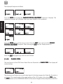
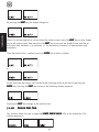
3.1 Ordering guide .................................................................................................................... 8
3.2 Ordering example................................................................................................................ 9
3.3 Safety related specifications ................................................................................................. 9
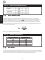
3.4 Performance characteristics ................................................................................................. 9
3.4.1 Accuracy ............................................................................................................................. 9
3.4.2 Resolution .......................................................................................................................... 10
3.5 Pressure side connection ................................................................................................... 1 1
3.6 Pressure ranges .................................................................................................................. 1 1
3.6.1 Pressure ranges in bar ........................................................................................................ 1 1
3.6.2 Max. Overload .................................................................................................................. 1 1
3.6.3 Burst pressure .................................................................................................................... 1 1
3.6.4 Natural frequency .............................................................................................................. 1 1
3.7 Rigid stem/flexible stem .....................................................................................................11
3.8 Electrical Data ................................................................................................................... 1 1
3.9 Temperature influence ....................................................................................................... 12
3.10 EMC requirements ............................................................................................................. 1 2
3.11 Materials ............................................................................................................................ 1 3
3.12 Mounting torque ................................................................................................................ 13
3.13 Environmental Protection ................................................................................................... 13
3.14 Weight ............................................................................................................................... 13
3.15 Dimensions........................................................................................................................ 1 3
3.13.1
3.13.1
3.1 OO
OO
ORDERINGRDERING
RDERINGRDERING
RDERING
GUIDEGUIDE
GUIDEGUIDE
GUIDE
The exact meanings of the letter/digit combinations are given in the corresponding sections of
chapter 3.

9
TECHNICAL DATA
3.23.2
3.23.2
3.2 EE
EE
EXAMPLEXAMPLE
XAMPLEXAMPLE
XAMPLE
FORFOR
FORFOR
FOR
ORDERINGORDERING
ORDERINGORDERING
ORDERING
3.33.3
3.33.3
3.3 SS
SS
SAFETAFET
AFETAFET
AFETYY
YY
Y
RELARELA
RELARELA
RELATEDTED
TEDTED
TED
SS
SS
SPEPE
PEPE
PECIFICACIFICA
CIFICACIFICA
CIFICATIONSTIONS
TIONSTIONS
TIONS
ATEX certificate No.: SIRA 02ATEX2244X
EX-Safety class EEx ia IIC T4 (Ta = -20°C to +80°C)
FM approvals Class I, Division 1 Groups B, C & D
Class II / III, Division 2 Groups E, F & G
CC
CC
Cerer
erer
ertified mtified m
tified mtified m
tified maxax
axax
aximum imum
imum imum
imum vv
vv
valuealue
aluealue
aluess
ss
s f f
f f
for EExor EEx
or EExor EEx
or EEx i i
i i
ia IICa IIC
a IICa IIC
a IIC
T4T4
T4T4
T4
Associated electrical equipment must satisfy the following conditions:
PrPr
PrPr
Pree
ee
ess
ss
sss
ss
surur
urur
ure:e:
e:e:
e:
Supply voltage max. 30 V DC
Current output max. 125 mA
Power output max. 900 mW
Inductivity max. 0.26 mH
Capacity max. 9.7 nF
TT
TT
Temperemper
emperemper
emperatat
atat
aturur
urur
ure:e:
e:e:
e:
Supply voltage 30 V DC
Current output max. 125 mA
Power output max. 900 mW
Inductivity max. 0 mH
Capacity max. 52 nF
3.43.4
3.43.4
3.4 PP
PP
PERFORMANCERFORMANC
ERFORMANCERFORMANC
ERFORMANCEE
EE
E
CHARACHARA
CHARACHARA
CHARACTERISCTERIS
CTERISCTERIS
CTERISTICTIC
TICTIC
TICSS
SS
S
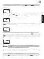
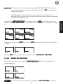
xx19xx - xx - x - xx - xx / xx - x - x - x - @xxx - xxxx
3.4.13.4.1
3.4.13.4.1
3.4.1 AA
AA
ACC
CC
CCC
CC
CURAURA
URAURA
URACYCY
CYCY
CY
(Linearity and repeatability)

10
TECHNICAL DATA
3.4.13.4.1
3.4.13.4.1
3.4.1AA
AA
AXX
XX
X11921192
11921192
1192XX
XX
X, ,
, ,
, XX
XX
X11941194
11941194
1194XX
XX
X
±0.15% (20% to 100% f.s.)
±0.25% (0% to 20% f.s.)
(0-3000 psi and above)
±0.25% (20% to 100% f.s.)
±0.50% (0% to 20% f.s.)
(0-1500 psi)
3.4.13.4.1
3.4.13.4.1
3.4.1BB
BB
BX1193X, X1193X,
X1193X, X1193X,
X1193X, XX
XX
X11951195
11951195
1195XX
XX
X
±0.15% (20% to 100% f.s.)
±0.25% (0% to 20% f.s.)
(0-1500 psi and above)
±0.25% (20% to 100% f.s.)
±0.50% (0% to 20% f.s.)
(0-750 psi)
3.4.13.4.1
3.4.13.4.1
3.4.1CC
CC
CXX
XX
X21922192
21922192
2192XX
XX
X, ,
, ,
, XX
XX
X21942194
21942194
2194XX
XX
X
±0.25% (20% to 100% f.s.)
±0.50% (0% to 20% f.s.)
(0-3000 psi and above)
±0.50% (20% to 100% f.s.)
±1.00% (0% to 20% f.s.)
(0-1500 psi)
3.4.13.4.1
3.4.13.4.1
3.4.1DD
DD
DX2193X, X2193X,
X2193X, X2193X,
X2193X, XX
XX
X21952195
21952195
2195XX
XX
X
±0.25% (20% to 100% f.s.)
±0.50% (0% to 20% f.s.)
(0-1500 psi and above)
±0.50% (20% to 100% f.s.)
±1.00% (0% to 20% f.s.)
(0.750 psi and above)
3.4.23.4.2
3.4.23.4.2
3.4.2 RR
RR
RESOLUTIONESOLUTION
ESOLUTIONESOLUTION
ESOLUTION
0.035% f.s. or better

11
TECHNICAL DATA
3.3.
3.3.
3.55
55
5PP
PP
PRERE
RERE
RESS
SS
SSURESURE
SURESURE
SURE
SIDESIDE
SIDESIDE
SIDE
CC
CC
CONNEONNE
ONNEONNE
ONNECTIONCTION
CTIONCTION
CTION
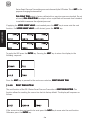
2 = 1/2" 20 UNF 2A (xx192x-x . . . )
3 = M18 x 1.5 (xx193x-x . . .)
4 or 5 = flange (xx194x-x . . . ) or (xx195x-x . . . )
3.63.6
3.63.6
3.6 PP
PP
PRESSURERESSURE
RESSURERESSURE
RESSURE
RANGESRANGES
RANGESRANGES
RANGES ( (
( (
(XXXX
XXXX
XX1919
1919
19XXXX
XXXX
XX))
))
)
3.6.13.6.1
3.6.13.6.1
3.6.1 PP
PP
PRESSURERESSURE
RESSURERESSURE
RESSURE
RANGESRANGES
RANGESRANGES
RANGES
ININ
ININ
IN
PSIPSI
PSIPSI
PSI
Model numberModel number
Model numberModel number
Model number PP
PP
Permittermitt
ermittermitt
ermitted pred pr
ed pred pr
ed pree
ee
ess
ss
sss
ss
surur
urur
ure re r
e re r
e ranan
anan
angg
gg
ge in Pe in P
e in Pe in P
e in PSISI
SISI
SI
xx19xx-xx-x-7.5c-x 0-750 (xx193xx & xx195xx only)(xx193xx & xx195xx only)
(xx193xx & xx195xx only)(xx193xx & xx195xx only)
(xx193xx & xx195xx only)
xx19xx-xx-x-1.5c-xm 0-1500
xx19xx-xx-x-3c-xm 0-3000
xx19xx-xx-x-5c-xm 0-5000
xx19xx-xx-x-7.5c-xm 0-7500
xx19xx-xx-x-10c-xm 0-10000
3.6.23.6.2
3.6.23.6.2
3.6.2 MM
MM
MAXAX
AXAX
AX. O. O
. O. O
. OVERLVERL
VERLVERL
VERLOO
OO
OADAD
ADAD
AD ( (
( (
(
WITHOUTWITHOUT
WITHOUTWITHOUT
WITHOUT
INFLINFL
INFLINFL
INFLUENCINGUENCING
UENCINGUENCING
UENCING
OPERAOPERA
OPERAOPERA
OPERATINGTING
TINGTING
TING
DD
DD
DAA
AA
ATT
TT
TAA
AA
A))
))
)
xx19xx 1.5 x full scale pressure up to 10,000 psi
3.6.33.6.3
3.6.33.6.3
3.6.3 BB
BB
BURSTURST
URSTURST
URST
PRESSUREPRESSURE
PRESSUREPRESSURE
PRESSURE
3 x nominal value, max. 30,000 psi
3.6.43.6.4
3.6.43.6.4
3.6.4 NN
NN
NAA
AA
ATURALTURAL
TURALTURAL
TURAL
FREFRE
FREFRE
FREQUENCYQUENCY
QUENCYQUENCY
QUENCY
50 Hz [-3db]
3.73.7
3.73.7
3.7 RR
RR
RIGIDIGID
IGIDIGID
IGID
STEMSTEM
STEMSTEM
STEM//
//
/FLEXIBLEFLEXIBLE
FLEXIBLEFLEXIBLE
FLEXIBLE
STEMSTEM
STEMSTEM
STEM ( (
( (
(
XXXX
XXXX
XX1919
1919
19XXXX
XXXX
XX-)-)
-)-)
-)
6 = 152 mm standard length for rigid version
6/18 = 152 mm stem length / 457 mm flexible stem
Other lengths on request
3.83.8
3.83.8
3.8 EE
EE
ELELE
LELE
LECTRICALCTRICAL
CTRICALCTRICAL
CTRICAL
DD
DD
DAA
AA
ATT
TT
TAA
AA
A
Configuration 4-arm Wheatstone bridge strain gauge with int. amplifier
Output signal 2-wire 4 - 20 mA, optional 2nd 2-wire 4 - 20 mA

12
TECHNICAL DATA
Supply voltage 12-30 VDC for EEx ia IIC T4 12-42 for FM approved explosion proof
models
Power consumption -20 mA
Zero balance (xx192x and xx194x)
0.25% for 3000 psi and above
0.5% for 1500 psi
(xx193x and xx195x)
0.25% for 1500 psi and above
0.5% for 750 psi
3.93.9
3.93.9
3.9 TT
TT
TEMPERAEMPERA
EMPERAEMPERA
EMPERATURETURE
TURETURE
TURE
INFLINFL
INFLINFL
INFLUENCUENC
UENCUENC
UENCEE
EE
E
ElEl
ElEl
Electrectr
ectrectr
ectroniconic
oniconic
onicss
ss
s hou hou
hou hou
houss
ss
sinin
inin
ingg
gg
g
Max. housing temperatures
Safety class T4 -20°C to +80°C
Compenstated +25°C to +300°C (option to 350°C) - snout
temperature range +25°C to +80°C - electronics
Zero and sensitivity shift due to temperature change on electronics housing
xx19xx ±0.15% f.s./55°C
DiDi
DiDi
Diaphraphr
aphraphr
aphragm (in cagm (in c
agm (in cagm (in c
agm (in contont
ontont
ontactact
actact
act w w
w w
with mediith medi
ith mediith medi
ith media)a)
a)a)
a)
Maximum temperature at the diaphragm
xx19xx 350°C
Zero shift due to temperature change on the diaphragm
xx19xx ±0.01 psi / 100°C
3.103.10
3.103.10
3.10 EMCEMC
EMCEMC
EMC
RERE
RERE
REQUIREMENTQUIREMENT
QUIREMENTQUIREMENT
QUIREMENTSS
SS
S
Conforming to CE in accordance with EMC directive.
Electromagnetic Interference DIN EN 550223 1995
Immunity DIN EN 61000-4-2 1995
Radiated, Radio Freq, etc. DIN EN 61000-4-3 1995 +A1:1998+A2:2000
Pulse Magnetic Field DIN EN 61000-4-9 1993 + A1:2001

13
TECHNICAL DATA
Surge Immunity DIN EN 61000-4-5 1995 + A1:2000
Conducted Disturbences DIN EN 61000-4-6 1996 + A1:2000
Power Frequency Magnetic Field DIN EN 61000-4-8 1993 + A1:2001
3.113.11
3.113.11
3.11 MM
MM
MAA
AA
ATERIALSTERIALS
TERIALSTERIALS
TERIALS
Diaphragm 15-5PH Mat. No. 1.4545 DyMax™ coated
Stem 17-4PH Mat. No. 517400
3.123.12
3.123.12
3.12 TT
TT
TORQUEORQUE
ORQUEORQUE
ORQUE
xx192x xx193x xx194x xx195x
max. 56.5 Nm max. 56.5 Nm max. 5.6 Nm max. 14.1 Nm
(500 inch-lbs.) (500 inch-lbs.) (50 inch-lbs.) (125 inch-lbs.)
min. 11.3 Nm min. 11.3 Nm min. 4.5 Nm min. 11.3 Nm
(100 inch-lbs.) (100 inch-lbs.) (40 inch-lbs.) (100 inch-lbs.)
3.133.13
3.133.13
3.13 EE
EE
ENVIRONMENTNVIRONMENT
NVIRONMENTNVIRONMENT
NVIRONMENTALAL
ALAL
AL
PROPRO
PROPRO
PROTETE
TETE
TECTIONCTION
CTIONCTION
CTION
TT
TT
TOO
OO
O IE IE
IE IE
IECC
CC
C 5 5
5 5
5
22
22
299
99
9
Electronics housing min. IP66, nema 4x
3.143.14
3.143.14
3.14 WW
WW
WEIGHTEIGHT
EIGHTEIGHT
EIGHT
5-10 lbs.
3.153.15
3.153.15
3.15 DD
DD
DIMENSIONSIMENSIONS
IMENSIONSIMENSIONS
IMENSIONS

14
TECHNICAL DATA
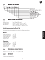
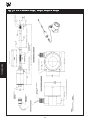
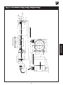
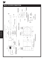
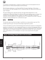
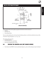
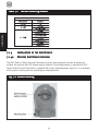
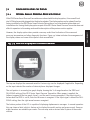
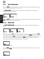
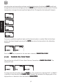
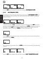
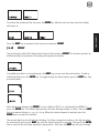
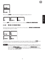
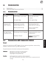
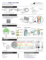
Fig. 3-1Fig. 3-1
Fig. 3-1Fig. 3-1
Fig. 3-1 IPX II Models S1192, S2192, N1192 & N2192IPX II Models S1192, S2192, N1192 & N2192
IPX II Models S1192, S2192, N1192 & N2192IPX II Models S1192, S2192, N1192 & N2192
IPX II Models S1192, S2192, N1192 & N2192

15
TECHNICAL DATA
3.88
( 98.6 )
2.09
( 53.1 )
2x
O
.312 (
O
7.9 ) MOUNTING HOLES
5.21
( 132.3 )
NOMINAL
4.70
( 119.4 )
4.88
( 122 )
M18X1.5THREAD 45
v
30'
44
v
30'
.80
20.3
.236
.227
5.99
5.77
.550
13.97
.630
.627
16.00
15.93
O
.394
.392
10.01
9.96
O
SNOUT
HEX
.62
( 15.8 )
.50
O
(
O
12.7 )
SST BRAIDED FLEXIBLE
PRESSURE HOSE
BENDIX CONNECTOR
PT1H-14-15P OR EQUIVALENT
LOCKING PROTECTIVE GROUND TERMINAL
4.08
( 103.6 )
2.00
O
(
O
.51 )
SPECIFIED FLEX
LENGTH
u
.12 (3mm)
TRANSDUCER/SENSOR
FLEX
RIGID
STEM CONFIGURATIONSSTEM CONFIGURATIONS
SPECIFIED RIGID LENGTH
SPECIFIED SNOUT LENGTH
u
.02 ( .51 mm )
6.78 ( 172 mm ) + SNOUT LENGTH + STEM LENGTH
u
.25(6.4mm)
10 ft ( 2.54 meters )
CABLE TO ELECTRONICS MODULE
BENDIX CONNECTOR
PT06W-14-15S
OR EQUIVALENT
LIQUIDTIGHT CABLE CONNECTOR
IP66 SUITABILITY
NOMINAL
NOMINAL
ELECTRONICSMODULE
3/4 -14 NPT PORT FOR
CUSTOMER CONNECTION
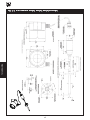
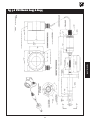
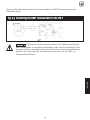
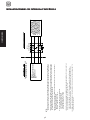
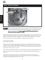
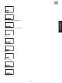
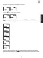
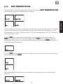
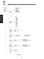
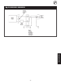
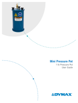
Fig. 3-2Fig. 3-2
Fig. 3-2Fig. 3-2
Fig. 3-2 IPX II Models S1193, S2193, N1193 & N2193IPX II Models S1193, S2193, N1193 & N2193
IPX II Models S1193, S2193, N1193 & N2193IPX II Models S1193, S2193, N1193 & N2193
IPX II Models S1193, S2193, N1193 & N2193

16
TECHNICAL DATA
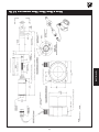
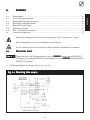
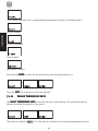
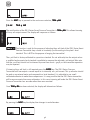
Fig. 3-3Fig. 3-3
Fig. 3-3Fig. 3-3
Fig. 3-3 IPX II Models S1194, S2194, N1194 & N2194IPX II Models S1194, S2194, N1194 & N2194
IPX II Models S1194, S2194, N1194 & N2194IPX II Models S1194, S2194, N1194 & N2194
IPX II Models S1194, S2194, N1194 & N2194

17
TECHNICAL DATA
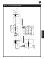
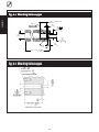
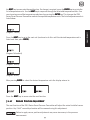
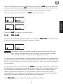
Fig. 3-4Fig. 3-4
Fig. 3-4Fig. 3-4
Fig. 3-4 IPX II Models S1195, S2195, N1195 & N2195IPX II Models S1195, S2195, N1195 & N2195
IPX II Models S1195, S2195, N1195 & N2195IPX II Models S1195, S2195, N1195 & N2195
IPX II Models S1195, S2195, N1195 & N2195

18
TECHNICAL DATA
Fig. 3-5Fig. 3-5
Fig. 3-5Fig. 3-5
Fig. 3-5 IPX II Models E1192 & E2192IPX II Models E1192 & E2192
IPX II Models E1192 & E2192IPX II Models E1192 & E2192
IPX II Models E1192 & E2192

19
TECHNICAL DATA
M18X1.5THREAD 45
v
30'
44
v
30'
.80
20.3
.236
.227
5.99
5.77
.550
13.97
.630
.627
16.00
15.93
O
.394
.392
10.01
9.96
O
SNOUT
HEX
.62
( 15.8 )
.50
O
(
O
12.7 )
SST BRAIDED FLEXIBLE
PRESSURE HOSE
LOCKING PROTECTIVE GROUND TERMINAL
4.08
( 103.6 )
2.00
O
(
O
.51 )
SPECIFIED FLEX
LENGTH
u
.12 (3mm)
TRANSDUCER/SENSOR
FLEX
RIGID
STEM CONFIGURATIONSSTEM CONFIGURATIONS
SPECIFIED RIGID LENGTH
SPECIFIED SNOUT LENGTH
u
.02 ( .51 mm )
6.78 ( 172 mm ) + SNOUT LENGTH + STEM LENGTH
u
.25(6.4mm)
10 ft ( 2.54 meters )
CABLE TO ELECTRONICS MODULE
FLATS
1.25
(32)
CONDUIT FITTING
3/4-14 NPT THREAD
3/4 -14 NPT PORT FOR
CUSTOMER CONNECTION
ELECTRONICSMODULE
NOMINAL
NOMINAL
LIQUIDTIGHT CABLE CONNECTOR
IP66 SUITABILITY
4.88
( 122 )
4.70
( 119.4 )
NOMINAL
5.21
( 132.3 )
2x
O
.312 (
O
7.9 ) MOUNTING HOLES
2.09
( 53.1 )
3.88
( 98.6 )
.40
10.2
1.72
43.8
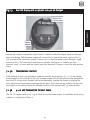
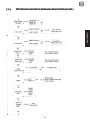
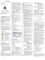
Fig. 3-6Fig. 3-6
Fig. 3-6Fig. 3-6
Fig. 3-6 IPX II Models E1193 & E2193IPX II Models E1193 & E2193
IPX II Models E1193 & E2193IPX II Models E1193 & E2193
IPX II Models E1193 & E2193

20
TECHNICAL DATA
Fig. 3-7Fig. 3-7
Fig. 3-7Fig. 3-7
Fig. 3-7 IPX II Models E1194 & E2194IPX II Models E1194 & E2194
IPX II Models E1194 & E2194IPX II Models E1194 & E2194
IPX II Models E1194 & E2194
Page is loading ...
Page is loading ...
Page is loading ...
Page is loading ...
Page is loading ...
Page is loading ...
Page is loading ...
Page is loading ...
Page is loading ...
Page is loading ...
Page is loading ...
Page is loading ...
Page is loading ...
Page is loading ...
Page is loading ...
Page is loading ...
Page is loading ...
Page is loading ...
Page is loading ...
Page is loading ...
Page is loading ...
Page is loading ...
Page is loading ...
Page is loading ...
Page is loading ...
Page is loading ...
Page is loading ...
Page is loading ...
Page is loading ...
Page is loading ...
Page is loading ...
Page is loading ...
Page is loading ...
Page is loading ...
Page is loading ...
Page is loading ...
Page is loading ...
Page is loading ...
Page is loading ...
Page is loading ...
Page is loading ...
Page is loading ...
Page is loading ...
Page is loading ...
Page is loading ...
Page is loading ...
Page is loading ...
Page is loading ...
Page is loading ...
Page is loading ...
Page is loading ...
Page is loading ...
Page is loading ...
Page is loading ...
Page is loading ...
Page is loading ...
Page is loading ...
Page is loading ...
-
 1
1
-
 2
2
-
 3
3
-
 4
4
-
 5
5
-
 6
6
-
 7
7
-
 8
8
-
 9
9
-
 10
10
-
 11
11
-
 12
12
-
 13
13
-
 14
14
-
 15
15
-
 16
16
-
 17
17
-
 18
18
-
 19
19
-
 20
20
-
 21
21
-
 22
22
-
 23
23
-
 24
24
-
 25
25
-
 26
26
-
 27
27
-
 28
28
-
 29
29
-
 30
30
-
 31
31
-
 32
32
-
 33
33
-
 34
34
-
 35
35
-
 36
36
-
 37
37
-
 38
38
-
 39
39
-
 40
40
-
 41
41
-
 42
42
-
 43
43
-
 44
44
-
 45
45
-
 46
46
-
 47
47
-
 48
48
-
 49
49
-
 50
50
-
 51
51
-
 52
52
-
 53
53
-
 54
54
-
 55
55
-
 56
56
-
 57
57
-
 58
58
-
 59
59
-
 60
60
-
 61
61
-
 62
62
-
 63
63
-
 64
64
-
 65
65
-
 66
66
-
 67
67
-
 68
68
-
 69
69
-
 70
70
-
 71
71
-
 72
72
-
 73
73
-
 74
74
-
 75
75
-
 76
76
-
 77
77
-
 78
78


Dynisco IPX II Series User manual
- Category
- Measuring, testing & control
- Type
- User manual
Ask a question and I''ll find the answer in the document
Finding information in a document is now easier with AI
Related papers
-
Dynisco 290 Series User manual
-
-
-
-
-
-
-
-
-
Other documents
-
 Nivetec UNICOMM SAT-504 User manual
-
Novus Submersible Hydrostatic Level Transmitter User manual
-
Novus WL420 User manual
-
Ashcroft GC55 User manual
-
 aFe Power 50-70111D User manual
-
 Simex XMD Owner's manual
-
 Sensor QSx-G2 HAZ User guide
-
 MIXX FreeStand Pro User guide
-
 dymax 1 Lb Pressure Pot Owner's manual
-
 Simex DMD 331 Owner's manual


