Page is loading ...

Service Guide 9968
9968-A
SER 9968
Alemite Corporation
PO Box 473515, Charlotte, North Carolina 28247-3515
www.alemite.com
Copyright © 2000 by Alemite Corporation9
This document contains confidential information that is the property of Alemite Corporation
670789 and is not to be copied, used, or disclosed to others without express written permission. Revision (4-00)
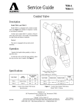
Figure 1 Medium-Pressure Stub Pump
Model 9968 Series - Model 9968 Shown
Description
The major components of stub pump model 9968 and
9968-A consists of an air-operated motor and a pump tube. The
air motor connects directly to a double-acting reciprocating
pump tube.
These medium-pressure stub pumps (5:1 ratio) are designed
to deliver all grades of oil.
Pump Extensions
Extensions that screw directly into the pump’s fluid inlet
allow the pump to accommodate different size drums and tanks.
Extensions are accessory items and are not included with the
pump. See Table 2.
Models 9968 and 9968-A
Model 9968 includes a 2 " NPTF (m) bung adapter that
allows installation directly onto original containers or bulk
tanks. The bung adapter is not included with model 9968-A.
Specifications
Air Motor
Pump Tube
Piston Diameter x Stroke Air Inlet
Maximum Air
Pressure
Inches Centimeters psi Bars
3 x 3-5/16 7.6 x 8.4 1/4 " NPTF (f) 150 10.3
For details on the air motor, refer to Service Guide SER 339413
Fluid Inlet Fluid
Outlet
Max. Fluid
Pressure Delivery/Minute
(Approximate)* Displacement
per Cycle
psi Bars Gallons Liters In 3Cm 3
1-1/2 " NPTF 1/2 " NPTF 750 52 7 26.5 7.2 118
* For detailed information, refer to Figure 3
Table 1 Medium-Pressure Stub Pump Specifications
Medium-Pressure Stub Pump
Pump Model Bung Adapter
9968 Included
9968-A Not Included

SER 9968 Medium-Pressure Stub Pump
Revision (4-00) 2 Alemite Corporation
Figure 2 Medium-Pressure Stub Pump Model 9968 and 9968-A- Exploded View

Medium-Pressure Stub Pump SER 9968
Alemite Corporation 3 Revision (4-00)
Repair Kits
Part No. Kit Symbol Description
393715 Kit, Repair (Includes tube of 393590 Teflon lubricant)
393708 Kit, Repair, Air Motor Keeper
393530-22 Kit, Seal [includes five (5) of item number 13]
393530-23 Kit, Seal [includes five (5) of item number 15]
Item
No. Part No. Description Qty Notes Numeric Order
Part # (Item #)
1 Motor Assembly, Air 1 See SER 339413 14536 (5)
1a Bolt, Carriage, 1/4 " -20 x 7-1/2 " 4 Included w/
Motor Assembly X171000-14 (10)
1b Nut, Serrated Flange, 1/4 " -20 4 X171003-10 (8)
2 328034 Connector, 1/4 " NPTF (m) 1 X171008-37 (7)
3 328030 Coupler, Air, 1/4 " NPTF (f) 1 171009-31 (28)
4 Screw, 3/8 " -24 x 3/4 " 1 171009-51 (21)
5 Washer, 3/8 " 1 171700-36 (19)
6 339429 Piston, Air 1 172190-22 (13)
7 X171008-37 Quad-Ring, 2-5/8 " ID x 3 " OD 1 Pack of Ten (10) 172190-23 (15)
8 X171003-10 O-Ring, 2-3/4 " ID x 3 " OD 1 172270-13 (27)
9 338089 Body 1 172409 (4)
10 X171000-14 O-Ring, 3/4 " ID x 15/16 " OD 1 Pack of Ten (10) 323693 (x)
11 338057 Adapter, Outlet 1 323707 (20)
12 339412 Keeper 4 323713 (30)
13 Seal, 1-5/16 " ID x 1-9/16 " OD 1 323778 (29)
14 338060 Bearing (Brass) 1 326750-B1 (24)
15 Seal, 1-5/16 " ID x 1-11/16 " OD 1 328030 (3)
16 338059 Spacer 1 328034 (2)
17 338106 Rod 1 335481 (26)
18 338120 Piston (Nylon) 1 335483 (25)
19 Ball, 9/16 " Dia. 1 338057 (11)
20 323707 Seat, Valve 1 338059 (16)
21 O-Ring, 1-7/8 " ID x 2 " OD 1 338060 (14)
22 Ring, Back-Up 1 338089 (9)
23 338090 Tube 1 338090 (23)
24 326750-B1 Adapter, Bung, 2 " NPTF (m) 1 Model 9968 338091 (22)
25 Washer, 1-1/8 " OD 1 338106 (17)
26 Spring, Tapered 1 338120 (18)
27 172270-13 Ball, 1-1/16 " Dia 1 339375 (1b)
28 O-Ring, 1-11/16 " ID x 1-7/8 " OD 1 339412 (12)
29 323778 Valve, Foot 1 339413 (1)
30 323713 Pin, 1/4 " Dia. x 1-25/32 " Long 1339425 (1a)
Kit Component for Early Model 9668 Pump 339429 (6)
x 323693 Gasket (Aluminum) 1
Legend:
Part numbers left blank (or in italics) are not available separately
designates a repair kit item

SER 9968 Medium-Pressure Stub Pump
Revision (4-00) 4 Alemite Corporation
700
SAE No. 10W -40 at 77 F (25 C)
600
500
400
300
200
100
001 2 34 5 6 7
800
5
10
15
20
25
30
35
0
40
100 psi (6.9 Bars)
150 psi (10.3 Bars) 150 psi (10.3 Bars)
50 psi (3.4 Bars)
50 psi (3.4 Bars)
Legend:
Air Pressure
Material Discharge Pressure
Air Consumption
Gallons per Minute
Liters per Minute
Delivery
510 15 20 25
100
200
300
400
500
600
700
800
900
Air Consumption
lpm
cfm
psi
1000
1100
Bars
Material Discharge Pressure (psi)
5
10
15
20
25
30
35
40
45
50
55
100 psi (6.9 Bars)
Accessories
Performance Curves
A pump’s ability to deliver fluid is based on the pressure (psi/Bars) and quantity
(cfm/lpm) of air supplied to the motor and the amount of fluid discharge [back] pressure to be
overcome within the system.
This chart contains curves based on three different air pressures. The curves relate delivery
in gallons (liters) per minute (X axis) to air consumption in cubic feet (liters) per minute (right
Y axis) and to fluid discharge pressure in psi/Bars (left Y axis).
Extension Description
Drum Tank
16-Gallon 55-Gallon 200/205 liter 250-Gallon
Bench-Top 275-Gallon
Obround
V-Cut 338147-1 338147-2 338147-3 338147-7
Threaded at both ends * 338246-1 338246-2 338246-3 338246-6
* NOTE: For use with low level cut-off valve part number 321206
Cover Assembly Description Drum
5-Gallon 16-Gallon 55-Gallon
Bolt-On - 338145 * -
w/ 2-Inch Bung Adapter Fitting 327817-4 338977 * 318040-4
* w/ sealing gasket
Table 2 Medium-Pressure Stub Pump Model 9968 and 9968-A Accessories
Figure 3 Delivery versus Discharge Pressure and Air Consumption

Medium-Pressure Stub Pump SER 9968
Alemite Corporation 5 Revision (4-00)

SER 9968 Medium-Pressure Stub Pump
Revision (4-00) 6 Alemite Corporation
Overhaul
NOTE: Refer to Figures 2 and 3 for compo-
nent identification on all overhaul proce-
dures.
Prior to performing any maintenance procedure, the
following safety precautions must be observed. Personal
injury may occur.
WARNING
Do not use halogenated hydrocarbon sol-
vents such as methylene chloride or 1,1,1-trichlo-
roethane in this pump. An explosion can result
when aluminum and/or zinc-plated parts in the
pump come in contact with halogenated hydrocar-
bon solvents.
Release all pressure within the system prior to
performing any overhaul procedure.
• Disconnect the air supply line from the pump
motor.
• Into an appropriate container, operate the
control valve to discharge remaining pressure
within the system.
Never point a control valve at any portion of your
body or another person. Accidental discharge of
pressure and/or fluid can result in injury.
Read each step of the instructions carefully. Make
sure a proper understanding is achieved before
proceeding.
Disassembly
Separate Air Motor from Pump Tube
1. Clamp the pump assembly in a soft-jaw vise at
Bung Adapter (24) or Body (9).
2. Remove Nuts (1b) that secure Body (9) to Air Motor
Assembly (1).
NOTE: The bottom end cap (339416) of the
Air Motor Assembly remains on the pump
tube during the next procedure.
3. With a side-to-side motion, pull the Air Motor
Assembly from the Body.
4. Remove Keepers (12) from the Body.
5. Remove the bottom end cap from the Body.
Pump Tube Assembly
Tube and Body
6. Unscrew Adapter (11) from the Body.
7. Remove O-Ring (10) from the Adapter.
8. Unscrew Tube (23) from the Body.
Step for Model 9968 Only
9. Remove the Bung Adapter from the Tube as required.
10. Remove O-Ring (21) and Back-Up Ring (22) from the
Tube.
Air Piston
11. Remove Screw (4) that secures Air Piston (6) to
Rod (17).
• Remove the Air Piston from the Rod.
12. Remove Washer (5) and Quad-Ring (7) from the Air
Piston.
13. Remove O-Ring (8) from the Body.
Rod
14. Pull the Rod assembly from the bottom of the Body.
15. Unscrew Valve Seat (20) from the Rod.
• Remove Ball (19) and Nylon Piston (18).
16. Remove Spacer (16) and Seal (15) from the Body.
17. Remove Bearing (14) and Seal (13) from the Body.
Foot Valve
18. Unscrew Foot Valve (29) from Tube (23).
19. Remove O-Ring (28) from the Foot Valve.
20. Remove Pin (30) from the Foot Valve.
21. Remove Washer (25), Spring (26), and Ball (27) from
the Foot Valve.

Medium-Pressure Stub Pump SER 9968
Alemite Corporation 7 Revision (4-00)
3. Install Pin (30) into the Foot Valve.
• Make sure the Pin retains the Washer properly and is
flush with the Foot Valve.
Body
4. Install O-Ring (8) onto the upper groove of Body (9).
5. Install and seat Seal (13) [heel end first] into the
bottom of the Body.
6. Install and seat Bearing (14) [small diameter first] into
the Body.
7. Install and seat Seal (15) [heel end first] into the Body.
CAUTION
Make sure the hole in the Spacer aligns with the
hole in the Body. Damage to components can
occur.
8. Install Spacer (16) [small diameter first] into the Body.
9. Install O-Ring (10) onto Adapter (11).
10. Screw the Adapter assembly into the Body.
• Tighten the Adapter securely.
Tube and Rod
11. Install and seat Nylon Piston (18) [openings upward]
onto the bottom of Rod (17).
12. Install Ball (19) into the Rod.
IMPORTANT: Do not tighten the Valve Seat
more than 1/4-turn once it contacts the Ny-
lon Piston. Distortion of the Nylon Piston
can occur which causes excessive drag on
the Tube.
Clean and Inspect
NOTE: Use the appropriate repair kit for
replacement parts. Make sure all the compo-
nents are included in the kit before discard-
ing used parts.
1. Clean all metal parts in cleaning solvent. The solvent
should be environmentally safe.
2. Inspect all parts for wear and/or damage.
• Replace as necessary.
3. Inspect Air Piston (6) for fatigue cracks.
• Replace as necessary.
4. Inspect Nylon Piston (18) and Rod (17) closely. Use a
magnifying glass to detect any score marks on the Rod.
• Replace as necessary.
5. Closely inspect the mating surfaces of all check valve
components for any imperfections. Ensure a smooth
and clean contact is obtained when assembled.
EXAMPLE: Place Ball (27) into Foot Valve
(29). Fill the Foot Valve with solvent. Make
sure no leakage occurs.
Assembly
NOTE: Prior to assembly, certain compo-
nents require lubrication. Refer to Table 3
for details.
NOTE: Refer to Figure 4 for a section view
of the pump tube assembly.
Foot Valve
1. Install O-Ring (28) onto Foot Valve (29).
2. Install Ball (27), Spring (26) [small diameter first], and
Washer (25) into the Foot Valve.
Item No. Description Item No. Description
Clean Oil
7 Quad-Ring, 2-5/8 " ID x 3 " OD 15 Seal, 1-5/16 " ID x 1-11/16 " OD
8 O-Ring, 2-3/4 " ID x 3 " OD 21 O-Ring, 1-7/8 " ID x 2 " OD
10 O-Ring, 3/4 " ID x 15/16 " OD 28 O-Ring, 1-11/16 " ID x 1-7/8 " OD
13 Seal, 1-5/16 " ID x 1-9/16 " OD
Magnalube-G Teflon Grease *
Coat the Bore of the Air Motor Assembly
* Part number 393590 is a 0.75 ounce (21.8 gm) tube of Magnalube-G Teflon grease
Table 3 Lubricated Components

SER 9968 Medium-Pressure Stub Pump
Revision (4-00) 8 Alemite Corporation
B
14
21
8
9
12
10
11
13
15
16
17
18
19
20
22
25
27
26
29
28
Detail B
A
Detail A
Lower Seal
Weep Hole
23
30
13. Screw Valve Seat (20) [with Loctite 222] into
the Rod. See Figure 2.
• Follow the thread sealant manufacturer’s
recommendations.
CAUTION
Install the Rod into the Body with a twist-
ing motion. Use care not to damage the
Seals.
14. Install the Rod assembly into the bottom of
the Body.
• Position the Nylon Piston flush with the
bottom of the Body.
15. Install Back-Up Ring (22) [concave upward]
onto Tube (23).
16. Install O-Ring (21) on top of the Back-Up
Ring.
17. Screw and seat the Tube assembly into the
Body.
• Make sure both Rings are not visible.
Step for Model 9968 Only
18. Slide Bung Adapter (24) onto the Tube.
19. Screw the Foot Valve assembly into the
Tube.
• Tighten the Foot Valve assembly securely
to the Tube and the Tube to the Body.
Air Piston
20. Install Quad-Ring (7) onto Air Piston (6).
21. Place the Air Piston [observe THIS SIDE
UP) on top of the Rod.
22. Install Screw (4) and Washer (5) that secures
the Air Piston to the Rod.
• Tighten the Screw securely.
Figure 4 Pump Tube Assembly 338067-A1- Section View
Refer to Figure 2 Parts List
for Parts Identification

Medium-Pressure Stub Pump SER 9968
Alemite Corporation 9 Revision (4-00)
Attach Air Motor to Pump Tube
IMPORTANT: The Air Motor Assembly must
be secured with at least one Carriage Bolt (1a)
and Flange Nut (1b) [preferably at the front].
23. Clamp the Body of the pump securely in a soft-jaw vise.
CAUTION
Install the RAM Air Motor Assembly with care. Dam-
age to Quad-Ring (7) and/or O-Ring (8) can occur.
HINT: Angle the Air Motor Assembly onto
the Quad-Ring and press the exposed portion
into Air Piston (6) with your thumb or finger.
24. Install and seat the Air Motor Assembly onto Body (9).
• Make sure Check Valve Assembly orients properly
with the inlet of the Air Motor.
25. Attach the Air Motor Assembly to the Body of the pump
tube with Keepers (12), Carriage Bolts, and Flange Nuts.
CAUTION
Do not overtighten Flange Nuts (1b). Component
damage can occur.
26. Torque the Flange Nuts in a crisscross pattern from 60 to
70 inch-pounds (6.8 - 7.9 Nm).
Bench Test and Operation
1. Screw Connector (2) [with thread sealant] into the air
motor inlet.
• Tighten the Connector securely.
2. Install Air Coupler (3) onto the Connector.
3. Slowly supply air pressure [not to exceed 35 psi
(2.4 Bars)] to the pump’s motor.
• The pump assembly should cycle.
If the pump assembly does not cycle, refer to the
Troubleshooting Chart for details.
With air pressure at zero:
4. Connect a product hose to the pump’s fluid outlet.
• Direct the hose into an appropriate collection
container.
5. Place the pump in oil.
6. Slowly supply air pressure to the pump’s motor.
7. Allow the pump to cycle slowly until the oil is free
of air.
If the pump assembly does not prime, refer to the
Troubleshooting Chart for details.
WARNING
Should leakage occur anywhere within
the system, disconnect air to the motor. Personal
injury can occur.
With air pressure at zero:
8. Attach a control valve to the outlet hose of the pump.
• Make sure the nozzle on the control valve is open.
9. Slowly supply air pressure to the pump’s motor.
10. Allow the pump to cycle slowly until the oil is once
again free of air.
11. Set the air pressure to the normal operating pressure.
12. Operate the control valve into a container.
13. Shut off the control valve.
• Visually inspect the pump for external leaks.
• The pump should not cycle more than once or
twice in one hour.
If the pump does not stall, refer to the
Troubleshooting Chart for details.
14. Check the motor for air leakage.
If the motor leaks, refer to the Air Motor Service
Guide for details.
Installation
Additional items that should be incorporated into the
air piping systems are listed in Table 4.
Part Number Description
5604-2 Moisture Separator
7604-B Regulator and Gauge
Table 4 Air Line Components

SER 9968 Medium-Pressure Stub Pump
Revision (4-00) 10 Alemite Corporation
Troubleshooting Chart
Pump Indications Possible Problems Solution
Pump does not cycle 1. Air motor not operating properly
2. Pump tube jammed and/or contains
loose components
3. Insufficient air pressure
1. Inspect air motor and rebuild or replace as
necessary
2. Rebuild pump tube
3. Increase air pressure
Pump will not prime 1. Excessive cycling speed
2. Pump leaking internally
3. Extension not sufficiently tight and/or
thread sealant missing or inadequate
1. Reduce air pressure
2. See Internal Leaks
3. Apply thread sealant* to male pipe
threads and tighten extension
Pump cycles rapidly 1. Product source empty
2. Extension not sufficiently tight and/or
thread sealant missing or inadequate
1. Replenish product
2. Apply thread sealant* to male pipe
threads and tighten extension
Pump will not stall (cycles
more than once or twice/hour) 1. Pump requires break-in period
2. Pump leaking internally
3. Pump leaking externally
4. Distribution system leaking
5. Extension not sufficiently tight and/or
thread sealant missing or inadequate
1. Operate the pump against moderate fluid
pressure for up to one hour
2. See Internal Leaks
3. See External Leaks
4. Correct leak
5. Apply thread sealant* to male pipe
threads and tighten extension
External Leaks
Product leakage visible at
weep hole in Body (9)1. Damaged Seal (15)
2. Damaged Rod (17)1. Replace Seal (15)
2. Inspect Rod (17) and replace as necessary
Product leakage visible at
bottom of Body (9)1. Tube (23) not sufficiently tight
2. Damaged O-Ring (19)1. Tighten Tube (23) into Body (9)
2. Separate Tube (23) from Body (9) and
replace O-Ring (21)
Air leakage at weep hole in
Body (9)Damaged Seal (13) Replace Seal (13)
Product leakage visible
between Tube (23) and Foot
Valve (29)
1. Foot Valve (29) not sufficiently tight
2. Damaged O-Ring (28)1. Tighten Foot Valve (29) into Tube (23)
2. Separate Foot Valve (29) from Tube (23)
and replace O-Ring (28)
Internal Leaks
Pump does not prime or
cycles continuously, or slowly
(once or twice/hour)
1. Foreign material between Ball (19)
and Valve Seat (20)
2. Foreign material between Ball (27)
and Foot Valve (29)
3. Worn or damaged Ball (19)
4. Worn or damaged Valve Seat (20)
5. Worn or damaged Ball (27)
6. Worn or damaged Foot Valve (29)
7. Worn or damaged Nylon Piston (18)
Locate and eliminate source of foreign
material
Disassemble pump tube, clean, inspect, and
replace worn or damaged components
* Do not apply thread sealant to the first two (2) threads. Contamination can occur.
Changes Since Last Printing
Changed O-Ring 171000-103 to Quad-Ring 171008-37
/