Page is loading ...

Guide
Gas Heating/Electric Cooling PY3P
NOTE: Read the entire instruction manual be%re starting the installation.
SAFETY CONSIDERATgONS
Note to ]Installer: This mannal must be le_t with tile equipment user.
Z_ WARNING: FIRE and EXPLOSION HAZARD
Failure to follow thiw warning could result in personal injury, death and/or property damage.
Do not store or use gasoline or other flammaNe vapors and Hquids in the vicinity of this or any other appliance.
WARNING: FmRE,EXPLOSION, ELECTRmOAL SHOCK HAZARD
Failure to folmow this warning could result in personal injury, death and/or property damage.
Do not use this unit if any part has been under water. Ummediately call a quNified service technician to inspect the unit and
to repJace any part of the control system which has been under water.
z_ WARNING: For your safety if you smell gas:
1. Do not try to Jight any appmiance.
2. Do not touch any electrical switch; do not use any phone in your building.
3. mmmediatNy call your gas supplier from a nearby phone. Follow the gas suppHer's instructions.
4. ff you cannot reach your gas supplier, call the fire department.
Z_ WARNING: ELECTRUCAL SHOCK HAZARD
Failure to follow this warning coutd resuR in persona{ injury and/or death.
Before perform{ng recommended maintenance, be sure the main power switch to unit is turned off and mock-out tag installed.
UNiT mNTRODUCTION
This PY3P unit is a small packaged gas heat/electric cooling system that can provide year-round comfort.
Starting or Shutting Unit Off
NOTE: Your combination heating/cooling unit is equipped with an automatic direct spark ignition and power combustion blower.
TO START (LIGHT) UN[T:
Z_ WARNING: FiRE and EXPLOSUON HAZARD
Failure to follow this warning could resumt in personaR injury, death and/or property damage.
Do not attempt to Hght by hand.
z_ DANGER: FURE, EXPLOSION, ELECTRUCAL SHOCK HAZARD
Failure to follow this hazard warning coutd result in personal injury, death and/or property damage.
1. Do not turn off the electricaJ power to unit without first turning off the gas supply.
2. Before attempting to start the gas heating section, familiarize yourseff with aH the procedures that must be followed.
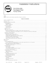
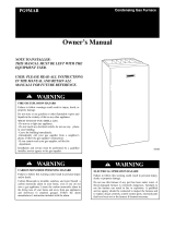
Refer to Fig. 2 %r location of unit access panel. Refer to Fig. 3 for location of gas valve. Refer to Fig. 4 while proceeding with the following steps.
1. Set the temperature selector on room thermostat to the lowest temperature setting and set system switch to HEAT.
2. (lose the external manual gas shutoff valve.
3. Turn off the electrical supply to the unit.
4. Remove the fi'ont access panel with a 5/16-in. nut driver.
Catalog No. OG-PY3P-02 Cancels: OG-PY3P-01 Printed in U.S.A. 02-07

Fig, 1=Gas Heating/Electric Cooling Unit
A05183
FRONT
AOOESSPANEL
Fig. 2=Gas Heating/Electric Cooling Unit
A05127
HOOD
BURNERS GAS VALVE
A05147
Fig, 3=Gas Heating/Electric Cooling Unit
5. Move the selector switch on the internal gas valve to the OFF position and wait 5 minutes.
6. Move the selector switch on the internal gas valve to the ON position.
7. Replace the front access panel.
8. Turn on the electrical supply to unit.
9. Open the extemal manual gas shutoff valve.
10. Set the temperature selector on room thermostat slightly above room temperature to start unit. The induced-draWl combustion air fan will
start. Main gas valve will open and main burners should ignite within 5 seconds. If the burner does not light within 5 seconds, the ignition
module will go into a Retry Mode a_er a period of approximately 22 seconds (tbliowing the 5-second ignition period).
If the burners do not light within 15 minutes of the initial call _br heal there is a lockout.

11.Setthetemperatureselectoronroomthermostattodesiredsetting.
z_ WARNING: FiRE and EXPLOSION HAZARD
Failure to follow this warning could rssuR in personal injury, death and/or property damage.
1. ff the main burners fNt to Hght, or the blower fails to start, shut down gas heating section and chit your donor for service.
2. Never attempt to manually Hght the main burners on unit with a match, lighter, or any other flame, if the electric sparking
device faiJs to light the main burners, refer to the following shutdown procedures, then can your dealer as soon as
possible.
TO SHUT UNIT OFF:
z_ WARNUNG: FURE, EXPLOSION, ELECTRICAL SHOCK HAZARD
Failure to follow this warning could result in personam injury, death and/or property damage.
Do not turn off the electrical power to unit without first turning off the gas supply.
NOTE: If unit is being shut down because the heating season has ended, make sure to turn on power to cooling system.
If unit is being shut down because of a malfimction, cali your dealer as soon as possible.
Should overheating occur or the gas supply fail to shut off. shut off the manual gas valve to the unit befk)re shutting off the electrical supply. Do
not use this unit if any part has been under water. Immediately call a qualified service technician to inspect the unit and to replace any part of the
control system and any gas control which has been under water.
Refer to Fig. 5 while proceeding with the following steps.
1. Set the temperature selector on room thermostat to lowest temperature setting and set system switch to OFF.
2. Close the external manual shutoft" valve.
3. Turn oft" the electrical power supply to the unit.
4. Remove the front access panel.
5. Move the selector switch on the internal gas valve to the OFF position.
6. Replace the f?ont access panel.
7. Restore electrical power to the unit and set system switch to COOL to ensure operation of the cooling system during the cooling season.
OPERATING YOUR UNIT
The operation of your system is controlled by the indoor temperature control (Thermostat). You simply adjust the thermostat and it maintains the
indoor temperature at the level you select. Most thermostats of heating and cooling systems have 3 controls: a temperature control selector, a FAN
control, and a SYSTEM or MODE control. Refer to your thermostat owner*s manual for more information.
To better protect your investment and to eliminate unnecessa Uservice calls, familiarize yourself with the following facts:
a. Cooling Mode
With the SYSTEM or MODE control set to COOL, your unit will run in cooling rhode until the indoor temperature is lowered to the love! you
have selected. On extremely hot days, your unit will run fi_)r longer periods at a time and have shorter "oft _' periods than on moderate days.
EL Gas Heat Mode
With the SYSTEM or MODE control of your indoor thermostat set to HEAT. your unit wi!l run in gas heating mode until the indoor temperature
is raised to the level you have selected. On cold days and nights, your system will typically run for longer periods of time and have shorter "oft *'
periods than on moderate days. This is the same as the COOLING MODE.
MAINTENANCE AND SENWOE
This section discusses maintenance that shoukl be per_i_}rmed on ),our system. Most maintenance should be performed by ),our dealer. You, as the
owner, may wish to handle some minor maintenance for your new unit.
C, Routine Maintenance
Ai1 routine maintenance should be handled by skilled, experienced personnel. Your dealer can hel r) yon establish a standard procedure.
For your safety, keep the unit area clear and free of combustible materials, gasoline, and other flammable liquids and vapors.
To ensure proper functioning of the unit, flow of condenser air must not be obstructed from reaching the unit. Clearance from the top of the unit
is 48 in. Clearance of at least 36 in. is required on sides except the power entry side (42 in. clearance) and the duct side (12 in. minimum clearance).
D, Maintenance and Care for the Equipment Owner
Before proceeding with those things you might want to maintain yourself, please carefully consider the following:
WARNUNG: FUME,EXPLOSION, ELECTRICAL SHOCK HAZARD
Failure to follow this warning could result in personal injury, death and/or property damage.
TURN OFF ALL ELECTRmCAL POWER TO YOUR UNIT AND INSTALL LOCK-OUT TAG BEFORE SERVlCmNG OR PERFORMING
MAmNTENANCE.
z_ CAUTION: CUT HAZARD
Faimure to follow this caution could result in personal injury,
When removing access panels or performing maintenance functions inside your unit, be aware of sharp sheet metam parts
and screws, ARhough special care is taken to keep sharp edges te a minimum, be extremely careful when handling parts or
reaching into the unit, Wear safety glasses, gloves, and appropriate protective clothing,
-3-


UNiT S_ZE
PY3P024-036
PY3P042-060
Table 1Mndoor=Air FiRer Data
F_LTER S_ZE
20 x 24
24 x 36 1
AiR FILTERS
The air filter(s) should be checked at least every 3 months and changed or cleaned whenever it becomes dirty, r)irty filters produce excessive stress
on the blower motor and can cause the motor to overheat and shut down. Table 1 indicates the correct filter size for your unit. Refer to Fig. 6 to
access the filters.
To replace or inspect filters (or accessory filter rack when supplied):
1. Remove the filter access panel using a 5/16-in. nut driver.
2. Remove the filter(s) by pulling it out of the unit. If the filter(s) is dirty, clean or replace with a new one.
When installing the new tilter(s), note the direction of the airflow arrows on the tilter frame.
If you have difficulty locating your air filter(s) or have questions concerning proper filter maintenance, contact your dealer _br instructions. When
replacing filters, always use the same size and type of filter that was supplied, originally, by the installer.
WARNING: FIRE AND UNIT OPERATION HAZARD
Failure to follow this warning could resuR in personat injury, death or property damage.
Never operate your unit without the filter(s} in place. An accumulation of dust and Hnt on internal parts of your unit can cause
loss of efficiency and blower motor and/or compressor damage.
FANS AND FAN MOTORS
Periodically, check the condition of fan wheel and housing and fan-motor shaft bearings. Contact your dealer for the required ammal maintenance.
HEAT EXCHANGER
To ensure dependable and efficient heating operation, the heat exchanger should be checked by a qualified maintenance person be_bre each heating
season, and cleaned when necessary. This checkout should not be attempted by anyone not having the required expertise and equipment to
properly do the job. Contact your dealer %r the required periodic maintenance.
EVAPORATOR AND CONDENSER COILS
(leaning of the coils should only be done by qualified service personnel. Contact your dealer for tile required annual maintenance.
CONDENSATE DRAIN
The condensate drain and condensate drain line should he checked and cleaned at the same time the cooling coils are checked by your dealer.
COMPRESSOR
AII compressors are factory-shipped with a normal charge of the correct type refrigeration grade oil. A compressor should rarely require additional
oil.
CONDENSER (OUTDOOR) FAN
Z_ CAUTUON: PERSONAL iNJURY HAZARD
Failure to follow this caution may resuR in personal injury.
Do not poke sticks, screwdrivers, or any other objects into revolving fan Nades.
The fan must be kept 5"ee of all obstructions to ensure proper cooling. Contact your dealer _br any required service.
ELECTRICAL CONTROLS AND WIRING
Electrical controls are difficult to check without proper instrumentations. If there are any discrepancies in tile operating cycle, contact your dealer
and request service.
REFRIGERANT CIRCUIT
The refi'igerant circuit is difficult to check for leaks without the proper equipment. If inadequate cooling is suspected, contact your local dealer
_br service.
Z_ WARNING: EXPLOSUON HAZARD
Failure to follow this warning could resuR in personal injury, death and/or property damage.
System under pressure. Regeve pressure and recover aH refrigerant before system repair or finaJ unit disposal Use aH
service ports and open aH flow-control devices, incJuding solenoid valves.
UNIT PANELS
After perfoiming any maintenance or service on the unit, be sure all panels are fastened securely in place to prevent rain from entering the unit
cabinet and to prevent disruption of the correct unit airflow pattern.

FILTERACCESS
PANEL* ACCESSPANEL
*Foraccessoryfitterrack. A05121
Fig. 6=FiRst Access Panel°Vertical Supply Shown
COMBUSTbON AREA AND VENT SYSTEM
The combustion area and vent system should be inspected visually beti_u'e each heating season. The normal accumulation of dirt, soot, rust, and
scale can result in loss of efficiency and improper pertiJrmance it" allowed to build up. This inspection should be done by a trained service person.
Z_ WARNUNG: FURE, EXPLOSION HAZARD
Faimure to follow this warning soured result in persona_ injury, death and/or property damage.
if your unit makes an especially loud noise when the main burners are ignited, shut down the heating section and call your
dearest.
/_ CAUTION: PERSONAL mNJURY HAZARD
Failure to follow this caution may rssuR in personal injury.
Components in heating section may be hot after unit has been started up. When observing flame, be careful not to get close
to or touch heating components.
E. Regular Dealer Maintenance
In addition to the type of routine maintenance you might be willing to per%tin, your unit should be inspected regularly by a properly trained service
technician. An inspection (preferably each year, but at least every other year) should include the following:
1. InspecUon of all flue product passages-including the burners, heat exchanger, and flue collector box.
2. Inspectmn of all combustion- and ventilation-air passages and openings.
3. (?lose inspection of all gas pipes leading to and inside of your unit.
and. if required, cleaning of the outdoor and indoor coils.
and. if required, cleaning of the indoor coil condensate drain.
and cleaning of blower wheel housing and motor.
of all supply-air and return-air ducts for leaks, obstructions, and insulation integrity. Any problems found should be resolved at
4, Inspection
5, Inspection
6, InspecSon
7, Inspectmn
this time.
8, Inspection
9. Inspection
10. Inspection
11, Inspection
of the unit base to ensure that no cracks, gaps, etc., exist which may cause a hazardous condition.
of the unit casing for signs of deterioration.
of all electrical wiring and components to ensure proper connection.
for leaks in the refrigerant circuit. Pressure-check to determine appropriate refrigerant charge.
12. Operational check of the unit to determine working conditions. Repair or adjustment should be made at this time.
Your servicing dealer may offer an economical service contract that covers seasonal inspections. Ask tiJr further details.
(omplete service instructions can be found in the unit Installation. Start-Up and Service Instructions.
g. Warranty Certificate
Unit PY3P has a limited warranty. Be sure to read the warranty caretully to determine the coverage for your unit.
-7-

G, Be?ore You Oail for Service _.
...check for several easily-solved problems.
If insufficient heating or cooling is suspected:
( ) Check the air filter %r dirt.
( ) Check for blocked return-air or supply-air grilles. Be sure they are open and unobstructed. If these checks do not reveal the cause, call your
servicing dealer.
If your unit is riot operating at all, check the following list ihr easy solutions:
() (heck to be sure that your thermostat teraperature selector is set below the indoor temperature during the cooling season or above the indoor
temperature during heating season. Be sure the SYSTEM switch or MODE control is in the (OOL or HEAT position and not in the OFF position.
( ) If your unit still f_dls to operate, call your servicing dealer for troubleshooting and repairs. Specify the model and serial numbers of your unit.
(Record them in this manual in the space provided.) If the dealer knows exactly which unit you have. he may be able to offer suggestions over
the phone, or save valuable tirue through knowledgeable preparation %r the service call.
H, in Ca_e of Tm'ouNe
If you perform the steps above and unit perfornrance is still unsatisfactory, shut off the mlit and call your dealer.
Dealer's Name
Telephone
Unit Model
Unit Serial Number
tzj 2007 Payne Heating & Cooling 7310 W, Morris St,, Indianapolis, IN 46231 --S-- Catalog No. OG-PY3P-02
/