Page is loading ...

TECHNICAL INSTRUCTIONS
for installation, use and maintenance
of hot water boiler
and installation additional equipment
BioTec Plus
HEATING TECHNIQUE
Centrometal d.o.o. - Glavna 12, 40306 Macinec, Croatia, tel: +385 40 372 600, fax: +385 40 372 611
TUBTP-08-2017-eng

These instructions are an integral part of this product. All rights reserved.
Reproduction of content of this document and transfer to third parties is
not allowed without written approval from manufacturer. Make sure the
instructions are always with the device, even if its sale / transfer of another
owner to the user or staff authorized for maintenance or repairs to consult.
i
READ THESE INSTRUCTIONS CAREFULLY BEFORE
INSTALLING THE BOILER TO HEATING SYSTEM!
Boiler must not be used by children or disabled persons (either
physicallyor mentally), as well as by person without knowledge or
experience, unless they are under control or trained by s person
responsible for their safety. Children must be supervised in the
vicinity of the product.
Boiler must not operate in flammable and explosive environment.
Before any work on the boiler, electric energy must be switched off.
Insufficient combustion air for chimney vent boilers with room air for
combustion can lead to dangerous conditions.
Make sure that the combustion air supply and discharge openings
are not reduced or closed off.
Keep doors to the boiler room closed.
Protect the boiler room and avoid rodents and birds from entering
and blocking the air openings.
Boiler cannot be placed in operation until above points are not met.
Technical instructions BioTec Plus
2

BioTec Plus 35 45
TIP
(kW)
(kW)
(kW)
(mbar)
(lit.)
(°C)
(°C)
(°C)
(°C)
(kg/s)
(kg/s)
(kg/s)
(kg/s)
(h)
(h)
(°C)
(°C/bar)
(°C)
(mbar)
(%)
(lit.)
(mm)
(lit.)
(lit.)
(lit.)
(W)
(W)
(W)
(W)
(W)
(W)
(W)
(W)
(V~)
(Hz)
(A)
(kg)
(bar)
(bar)
(°C)
(mm)
(pcs.)
(R)
(R)
(R)
(R)
25
25
12,5-25
7,5-25
138
90-170
90-130
70-110
60-110
0,019
0,0206
0,010
0,0553
3,5
-
12,8
90
1,6
10,4
80
1100
110
60
5
1100
45
30
5
5,1
750
150
8
35
17 -3,5 5
10,2-35
167
90-170
90-130
70-110
60-110
0,022
0,030
0,012
0,0080
4
-
25,1
144
1,6
10,4
148
1100
116
68
5
1100
48
33
5
5,1
875
160
10
45
22,5-45
13,5-45
187
90-170
90-130
70-110
60-110
0,027
0,0385
0,014
0,0121
4
-
41,6
176
2,5
20,2
148
1100
122
75
5
1100
50
35
5
5,1
930
180
10
600×250×600 600×400×600 600×400×735
Boiler
connections
Flow and return pipe (male thread)
Charge/discharge (female thread)
Heat exchanger connector (male thread)
Connector of exchanger sensor (female thread)
WOOD: A by 303-5:2012; B by EN ISO 17225-5:2014-09
WOOD PELLETS: C1 by EN 303-5:2012; A1 by EN ISO 17225-2
Nominal heat output
Heat output range (wood)
Heat output range (wood pellets)
Boiler class (wood / wood pellets)
Required chimney underpressure
Water amount in boiler
Exhaust gas temperature at nominal heat output (wood)
Exhaust gas temperature at nominal heat output (wood pellets)
Exhaust gas temperature at minimal heat output (wood)
Exhaust gas temperature at minimal heat output (wood pellets)
Exhaust mass flow at nominal heat output (wood)
Exhaust mass flow at nominal heat output (wood pellets)
Exhaust mass flow at minimal heat output (wood)
Exhaust mass flow at minimal heat output (wood pellets)
Minimum operating time at rated power (nominal Q ) (wood)
N
Minimum operating time at rated power (nominal Q ) (wood pellets)
N
Min. inlet water tem. at the boiler supply water connection
Cold water tem. and pressure for safety heat exchanger
Setting range for temperature controller (wood / wood pellets)
Boiler resistance on water side at nominal output (dT=10°C)
Fuel moisture content
Fuel size
Fuel loading chamber capacity (wood)
Fuel loading chamber dimensions (D×W×H) (wood)
Firebox volume (wood pellets)
Combustion chamber volume (wood pellets)
Pellet tank volume
Combustion chamber type
Required minimum accumulation volume (tank) next to boiler
Maximal electrical power input (wood)
Auxiliray power requirements at Q (wood)
N
Auxiliray power requirements at Q (wood)
min
Standby power (wood)
Maximal electrical power input (wood pellets)
Auxiliray power requirements at Q (wood pellets)
N
Auxiliray power requirements at Q (wood pellets)
min
Standby power (wood pellets)
Supply voltage
Frequency
Max. electrical current
Current type
Total mass - (boiler with casing and accessories)
Max. operating overpressure
Test pressure
Max. operating temperature
Flue gas tube - external diameter
Number of turbulators
Heating appliance working
Heating appliance working
31
5
10
60
10-15°C / 2 bar
max. 90 / 65 - 90
max 25 % for wood, max. 12% for wood pellet
(450-550) x 70 x 50 for wood, fi6
underpressure
by EN 303:2012-point 4.4.6
230
50
~
2,5
5,5
90
6/4"
3/4"
3/8"
1/2"
with fan
under non-condensing conditions
31
15,5-31
9,3-31
167
90-170
90-130
70-110
60-110
0,022
0,0262
0,012
0,0075
4
-
19,7
144
1,6
10,4
148
1100
114
65
5
1100
47
32
5
5,1
875
160
10
Fuel type
600×400×600
29
29
14,5-29
8,7-29
167
90-170
90-130
70-110
60-110
0,0209
0,0243
0,011
0,00234
4
-
17,3
144
1,6
10,4
148
1100
112
63
5
1100
46
31
5
5,1
875
160
10
600×400×600
15
3
Technical instructions BioTec Plus

Boiler
dimensions
(A)
Depth
(B)
Width
(C)
Height
1450
1255
1450
Other
dimensions
(C1)
Height
1450
1260
1585
760 1260
1450
1255
1450
760
1605
1055
1350
760
1450
1255
1450
760
BioTec Plus 25 / 29 / 31 / 35
BioTec Plus 29 BioTec Plus 45
BioTec Plus 35
BioTec Plus 25 BioTec Plus 31
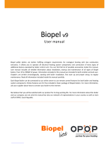
INNER PARTS VIEW FOR BOILERS BioTec Plus 25-45
Technical instructions BioTec Plus
4

BioTec Plus 45
DM - Flue gas tube connection
DO - Cover of lower openings of the flue gas chamber
DS - Lower refractory stone (chamotte) (2 parts)
DV - Lower boiler door (wood)
EH - Electric heater (pellets)
FO - Photocell
GV - Upper boiler door (wood)
KA - Heat exchanger connection (safety cooling
system) (wood)
KR - Digital boiler controller
LS - Lambda probe
MA - Magnetic valve
ME - Cleaning mechanism assembly (pellets)
MP - Primary air actuator
MS - Secondary air actuator
MV - Upper door microswitch
OD - Air-vent
OL - Combustion chamber temperature sensor
PAD - Ash tray (wood)
PAP - Ash tray (wood pellets)
PB - Pellet burner
PL - Main flow
PO - Door for cleaning of pellet burner
PP - Filling / drainage
PR - Return flow
PS - Pellet tank cover
PT - Pressure switch
RG - Fuel level sensor (pellet)
RSE - Backfire protection valve (RSE)
SK - Main switch
SO - Casing cover (removable) for acces to electric
parts (pellets)
ST1 - Safety thermostat (wood)
ST2 - Safethy thermostat (wood pellets)
SV - Middle boiler door (wood)
TI - Heat exchanger output (safety
cooling system) (pellet)
TO - Thermal safety valve sensor
connection (safety cooling system) (wood)
TU1 - Heat exchanger connection -
thermal safety valve connection point
(safety cooling system) (wood)
TU2 - Heat exchanger input (safety
cooling system) (pellet)
TV - Built-in thermal safety valve (safety cooling
system)
VC - Connection tube
VD - Opening for cleaning of the flue gas chamber
VR - Lower boiler door (pellet)
VT - Fan
ZL - Sheet metal protection cover (wood)
ZP - Flue gas tube cleaning lever
CLEANING SET:
CC - Flue gas tubes cleaning brush
GG - Scraper for upper refractory stone (chamotte),
flue gas chamber and place around lower chamotte
cleaning
GS - Scraper for cleaning of the lower refractory stone
(chamotte)
ZN - Holder for cleaning set
15
5
Technical instructions BioTec Plus

1.1. CHARACTERSTICS OF THE BioTec Plus BOILER
1.0. GENERAL
The BioTec Plus boiler is produced in compliance with the EN 303-5:2012 norm, which enables
the required level of functioning and minimal environmental pollution, through the firing with wood
logs and wood pellets. The system of flue gases conduction and their additional burning out,
enables its high efficiency, which makes this product extremely economical.
Widely sized left side fuel loading door enables firing with large pieces of wood logs and very
simple and easy cleaning and maintenance. The wood gasification principle enables a complete
fuel burning so maintenance of left part of the boiler is set to minimum. One filling of logs lasts up to
4 hours, depend about nominal heat output. There is also a possibility of prolonging the firing
process to the entire day, if the heating requirement is decreased. The boiler can keep the glow up
to 12 hours (depends on the quality of the wood), during which period it is not necessary to repeat
the start firing process.
In the right side of the boiler is installed the burner for wood pellet firing with the automatic firing
and automatic self-cleaning function which enables the reliable operation also with the low quality
wood pellets.
The boiler must be connected to the central heating system with return flow protection and with
properly sized water accumulation tank(s).
Boiler operation is managed with inbuilt boiler control unit using two boiler sensors, sensor in
combustion chamber, flue gas sensor and lambda probe, motors for primary and secondary air
intake for combustion and modulating underpressure fan on flue gases outlet from boiler. Boiler
control unit can run return flow protection, buffer tank management, one heating circuit with
circulation pump and 3-way mixing valve with actuator steered by outer temperature sensor and
room corrector and DHW water heater tank pump.
With boiler BioTec Plus it is easy to handle, integrated control unit with color touch screen assures
reliable and simple boiler operation. With installed accumulation (buffer) tank excess of produced
heat is accumulated into the tank and can be consumed when needed. Because of accumulation
tank, firing of the wood can be planned in a reasonable time, and in the case of mild outside
temperature, space heating and DHW heating without firing boiler is also possible for several
days, or just start pellet side of the boiler.
The boiler is delivered together with thermal insulation, covered by a metal casing on two wood
pallets.
Steel hot water boiler BioTec Plus has two separate combustion chambers inside the common boiler
water chamber. Boilers BioTec Plus, nominal heat output 25, 29, 31, 35 and 45 kW, are designed for
wood log firing in left part and wood pellet firing in right part of the boiler. The wood gasification
principle enables a complete fuel burning in left part of the boiler. Logs up to 550 mm long can be
inserted into the large combustion chamber. The burning period of a single fill of logs is up to 4 hours,
depend about nominal heat output. The boiler can keep the glow even 12 hours, which means that in
this period it is not necessary to fire up the boiler in order to keep the heating process. In the right
side of the boiler is installed the burner for wood pellet firing with the automatic firing and automatic
self-cleaning function which enables the reliable operation also with the low quality wood pellets.
Boiler operation is controlled with inbuilt boiler control unit using two boiler sensors, sensor in
combustion chamber, flue gas sensor and lambda probe, motors for primary and secondary air for
combustion and modulating underpressure fan on flue gases outlet from boiler. Boiler must be
connected to one adequately designed chimney and to the central heating system with return flow
protection and adequately designed water accumulation tank (CAS).
Technical instructions BioTec Plus
6

All local regulations, including those referring to national and European standards need to be
complied with when installing the appliance. The boiler must not be modified unless using the
tested original accessories we provide or if the work is undertaken by our Customer Service. Only
fit original spare parts. These can be obtained from your customer service partner or directly from
ourselves. European standards need to be complied with when installing the appliance.
Regular care and cleaning of the appliance, flue gas outlets, connecting piece and flue.
CAUTION:
The flue may block if the boiler is heated again after a long period of it not being used. Before
starting the boiler, have the flue checked by a specialist (chimney sweep). Ensure sufficient
supply of fresh air in the installation room when heating. The air must be replaced at least 0.8
times an hour through constant and reliable room venting. Fresh air may have to be provided from
outside if the windows and doors in the room where the boiler is installed are well sealed or if this
room contains other equipment, such as extractor hoods, clothes dryer, fan etc.
1.2. SAFETY PRECAUTIONS
1.3. IMPORTANT INFORMATIONS
This symbol indicates measures for protection against accidents and warning
for the user and / or exposed persons.
The boiler and related accessories are state of the art and meet all applicable safety regulations.
The control unit, wiring chamber, el. heater, safety cut-out STB thermostat, fan, grid cleaning
mechanism, flue gas tubes cleaning mechanism and pellet supply mechanism are integrated into
the BioTec Plus. They are operate at a voltage of 230V AC. Improper installation or repair can
pose the danger of life-threatening electric shock. Installation may beperformed only by
appropriately qualified technicians.
Caution symbols:
Please take careful note of the following symbols in this Operating Manual.
Concerning the specific need of sanitary hot water, the BioTec Plus boiler can be connected to one
of water heaters produced by our company. We suggest the combination with wall hanged SKB
Digi or LKB Digi water heaters, as well as with floor standing TB water heaters or accumulation
tanks CAS-B. If the future connection to the solar system has been planned, boiler can be
connected to combined accumulation tank CAS-BS or STEB solar water heater. Boiler is tested
and certified according to the European standard EN 303-5:2012 and meets class 5. It is
manufactured in compliance with ISO 9001 and ISO 14001 standards.
Although the boiler has two separate furnaces, boiler connects to one properly selected chimney.
15
7
Technical instructions BioTec Plus

1.4. WOOD GASIFICATION COMBUSTION PROCESS (wood side)
Combustion process is carried out in double combustion chamber in several phases. After filling
the upper chamber with logs, glow dry the logs, and at temperature 100÷300°C logs are beeing
gasified. The gases created in such process are mixed with the oxygen from air and burn out
completely with high temperature.
Fuel: wood logs with moisture content up to 20% (max. 25%), minimum size must be bigger than
a nozzle in refractory stone (chamotte) of the upper chamber. This demand for moisture content is
fulfilled with wood dried on air at least 12 months.
Wood pellets are used as fuel in right side of BioTec Plus boiler. Wooden pellets are bio-fuel made
of wooden wastes. Pellets can be packed in different packaging: in bags (15 kg or 1000 kg), or as
3
bulk in large (underground) tanks ( 4 - 15 m ) or in basement spaces. Recommended properties of
pellets for firing in BioTec Plus boilers are the following:
- heating value >= 5 kWh/kg (18 MJ/kg)
-diameter <= 6 mm
-max. moisture content <= 12 %
-max. dust content <= 1,5 %.
1.5. FIRING PROCESS IN WOOD PELLET SIDE
Technical instructions BioTec Plus
8

2.0. DELIVERY PACKAGE
Boiler BioTec Plus is delivered in parts for easier transportation and mounting to boiler room.
Basic equipment is delivered seperately:
- left part of the boiler for wood firing with mounted thermal insulation (on wood pallet) with
inbuilt:
- color touch screen display control unit
- sensor in combustion chamber
- flue gas sensor
- boiler sensor
- lambda probe
- 2 actuators for primary and secondary air
- flue gas modulating fan
- microswitch for upper boiler door
- STB safety thermostat
- right part of the boiler for wood pellet firing with mounted thermal insulation (on wood
pallet) with inbuilt:
- photocell
- cleaning mechanism with movable grate
- pellet tank
- feeder screw
- backfire protection by rotation valve (RSE)
- pellet level sensor
- magnetic valve for air
- thermal safety valve
- electric heater
- pressure switch
- STB safety thermostat
- boiler sensor
- ash tray
- Additional sensors in basic delivery:
- 2 × Buffer tank sensors
- 1 × Outer temperature sensor
- 1 × Return flow sensor
- 1 × DHW sensor
- 1 × Room corrector (CSK)
- cleaning brush, two scrapers and holder for cleaning set and portable ash tray (for left
part of the boiler (wood))
- set for connecting left and right side of the boiler: gasgets, screws, nuts.
- connection tube for connecting left and right side of the boiler
15
9
Technical instructions BioTec Plus

25
29
31
35
45
5/4''
5/4"
5/4"
5/4''
5/4''
Magna3 32-60
Magna3 32-60
Magna3 32-60
Magna3 32-60
Magna3 32-60
6/4''
6/4"
6/4"
6/4''
6/4''
Recommendations for the VTC valve, circulation pump and water accumulator CAS - according
to the boiler output:
Heat output
range
(kW)
Connection
VTC 512
(outer thread)
Connection
VTC 531
(internal thread)
Circulation pump type
(like Grundfos)
Volume of CAS accumulation
tank for BioTec Plus
wood gasification boilers
Minimum 50 litres / kW of boiler
2.1. ADDITIONAL EQUIPMENT
Recommendations for the LTC units and the water accumulators CAS - according to the boiler
output:
Minimum 50 litres / kW of boiler
25, 29, 31, 35
45
5/4''
--
--
6/4''
Heat output
range
(kW)
Connection
LTC 261
(internal thread)
Connection
LTC 271
(internal thread)
Volume of CAS accumulation
tank for BioTec Plus
wood gasification boilers
Additional equipment is not included in basic delivery. Obligatory
additional equipment must be purchased seperately. Other additional
equipment can be purchased optionally.
i
For closed heating systems:
- Thermal safety valve
- Safety-airvent group (2,5 bar)
- Expansion vessel for closed heating systems (size according the volume of heating installation,
including buffer tank volume)
For open heating systems:
- Open expansion vessel (size according the volume of heating installation, including buffer tank
volume)
2) OTHER ADDITIONAL EQUIPMENT:
- CAL alarm box (light/speaker)
- CM2K-B module for regulation 2+ heating circuits (max. 4 units.)
- GSM alarm module for mobile network
- Room thermostat
- Automatic flue gas tubes cleaning
- Pellet suction system CVT + CentroPelet box (pellet feeding box)
- Pellet suction system CVT + Feeder screw
- Pellet tank on wheels with volume of 780 l with feeder screw for filling standard installed pellet
tank
CAL alarm box
(light/speaker)
CM2K-B module
for regulation
2+ heating circuits
GSM alarm module
for mobile network
Room corrector (CSK)
(basic equipment)
1) OBLIGATORY ADDITIONAL EQUIPMENT:
- accumulation (buffer) tank for heating system (CAS (min. liter according to local regulation),
m ).inimum 50 litres / kW of boiler
- return flow protection - 3-way mixing valve with actuator (protection valve) or 3-way thermostat
valve (60°C) (like ESBE VTC 512, VTC 531, LTC 261, LTC 271).
Technical instructions BioTec Plus
10

3.0. BOILER / ADDITIONAL EQUIPMENT POSITIONING AND ASSEMBLY
The positioning of the boiler has to be carried out the authorized person. We suggest the
positioning on the solid concrete basis, which height is between 50-100 mm. The boiler room has
to be absolutely protected from freezing and properly ventilated. The boiler has to be positioned in
order to enable its connecting to the chimney (see point 3.) and heating installation as well as its
servising during the functioning process, cleaning and maintenance (Figure 1). The connection of
the boiler to the central heating system is obligatory with the one or more CAS water
accumulator buffer tanks, depending of the boiler's power. It is recommended to connect
minimum 50 liters water accumulation to each 1 kW boiler power (i.e. for the 45 kW boiler
minimal water accumulation should be 2.250 liters). The boiler should not be used without being
connected to the water accumulation tank. It must be connected to the CAS water accumulator
obligatory with return flow protection through an 3-way mixing valve with actuator (protection
valve) or 3-way thermic valve (like ESBE VTC 512, VTC 531 (60°C), LTC 261, LTC 271 (60°C)).
WARNING!
Flammable items must not be placed on the boiler and within the minimum distances
shown in Figure 1.
Figure 1. Minimum distance from the boiler room walls
*valid for closest tank to the wall
15
11
Technical instructions BioTec Plus

3.1. INSTALLATION OF DELIVERED PARTS
BioTec Plus is delivered on two wooden pallets. It must be mounted like is described on next
pages of these technical instructions. After the boiler is mounted, should be positioned in the
boiler room (see point 2.0.). Base protection with stone wool push under the boiler as shown in
figure 2.a.
In upper chamber of the left side of the boiler are delivered (figure 2.b):
1. holder for cleaning set and 2 cleaning scrapers and cleaning brush
2. room corrector and sensors (2 buffer tanks sensors, 1 return flow sensor, 1 DHW sensor, 1
outer sensor)
Holder for cleaning set can be positioned on lateral side of the boiler (A) or to the wall (B), near the
boiler and easy accessible. On this holder should be placed cleaning set (2 scrapers and brush).
Sensors and room corrector should be connected according heating installation and connecting
scheme.
CHECKING FLUE GAS CHAMBER LID
Before connecting of left (fuel: wood) and right (fuel: wood pellets) sides of boiler is necessary to
check if is right flue gas chamber lid it properly tight. Remove casing cover lid and additionally tight
screws on flue gas chamber lid (like is shown on figure below). Acces to right flue gas chamber will
be disabled after connection left and right side of the boiler.
Technical instructions BioTec Plus
12

CONNECTING LEFT AND RIGHT SIDE OF THE BOILER
Left part of the boiler
(fuel: wood)
Right part of the boiler
(fuel: wood pellets)
Detail 1 Detail 2
Detail 1 Detail 2
Prepared flange with holes on left part
of the boiler. First hole (left) have circle
shape, other five holes are slitted (have
possibility for height niveling).
Prepared flange on right side of the
boiler. Flange have factory glued
gasket and factory mounted six screws
M12.
15
13
Technical instructions BioTec Plus

STEP 1:
Sheet metal protection
cover
BioTec Plus - left part of the boiler section view
Remove sheet metal protection cover through the upper boiler door.
STEP 2:
It’s necessary draw closer left side of the boiler to right side of the boiler. Screws from flange on right
side of the boiler must get into flange holes on left side of the boiler. See figure on the next page.
Technical instructions BioTec Plus
14

A - hole with circle shape; other holes are slitted for height niveling possibility.
Screws from flange on right side of the boiler must get into flange holes on left side of the boiler like is
showned on figure above.
BioTec Plus - left part of the boiler section view
STEP 3:
Put washer, toothed washer and nut on screw like is showned on figure above (B). Tight nut but not
completely tight.
BioTec Plus - left part of the boiler section view
15
15
Technical instructions BioTec Plus

STEP 4: BioTec Plus - left part of the boiler section view
Put washers, toothed washers and nuts on all other screws and start tigth them. If is needed, nivel
boiler (holes are slitted for niveling). Thight hard all six nuts.
STEP 5:
Left and right side of the boiler have adjustable foots. Adjust it if is necessary. Boiler foots must
touching boileroom floor.
Technical instructions BioTec Plus
16

STEP 6:
1
2
3
prepared sockets on left side
of the boiler (wood)
1
2
3
prepared plugs on right side
of the boiler (wood pellets)
On left side of the boiler (wood) are prepared sockets, on right
side of the boiler (wood pellets) are prepared plugs. Cabels must
be connected in right order: 1-1; 2-2; 3-3;
15
17
Technical instructions BioTec Plus

Figure 2.b Delivered parts
Cleaning set
Sensor set
Position od cleaning set - on the boiler. Position od cleaning set - on the wall.
Figure 2.a Base protection with mineral wool
Push base protection under the boiler
Technical instructions BioTec Plus
18

4.0. CONNECTION TO THE CHIMNEY
Properly dimensioned and built chimney is the precondition for a safe and reliable operation of the
boiler and economic heating. The chimney has to be good insulated, gas-proof and smooth. On
the lower part of the chimney, a cleaning door has to be built in. Brick layed chimney has to have 3
layers with an stone wool thermal insulation in the middle. The thickness of the insulation should
be 30 mm, if the chimney is situated inside the building, i.e. 50 mm if the chimney is situated
outside the building. Inside chimney diameter dimensions depend on its height and on the
boiler thermal output (Figure 5.). The temperature of the flue gases on chimney exit point
should be minimum 30°C higher then the temperature of their condensating point. The choice and
the construction of the chimney should be performed by an authorized person. Minimal distance
between boiler and the chimney is 500 mm. The flue gas tube has to have an inclination of 30-45°
to the chimney (Figure 3.). In order to unable entering of the condensate from the chimney into the
boiler, 10 mm of the flue gas tube length has to be inserted deaper inside the chimney. It is
obligatory to insulate the chimney connection tube with a mineral stone wool of 30-50 mm
thickness. All installation works must be made in accordance with valid national and European
standards.
H - Useful chimney height
Figure 3. - Possible connecting of the BioTec Plus boiler to the chimney
Possible way of connecting to the
chimney of the BioTec Plus 25-35 boiler
(recommendation)
Possible way of connecting
to the chimney of the Bio-Tec-L boiler
(Only BioTec Plus 45 because of position
of the fan)
15
19
Technical instructions BioTec Plus

10
15
20
25
31
35
40
45
50
60
70
80
90
100
110
5 10 15
18
20
22
25
30
34
6 7 8 9
An example of the chimney selection:
- boiler output: 25 kW
- Fuel: wood logs, wood pellets
- required useful chimney height: H=8 m
- required inner chimney diameter: 18 cm
- boiler output: 29 kW
- Fuel: wood logs, wood pellets
- required useful chimney height: H=8 m
- required inner chimney diameter: 18 cm
- boiler output: 31 kW
- Fuel: wood logs, wood pellets
- required useful chimney height: H=8 m
- required inner chimney diameter: 18 cm
- boiler output: 35 kW
- Fuel: wood logs, wood pellets
- required useful chimney height: H=8 m
- required inner chimney diameter: 20 cm
- boiler output: 45 kW
- Fuel: wood logs, wood pellets
- required useful chimney height: H=8 m
- required inner chimney diameter: 22 cm
Figure 5. - Dimensioning of the chimney for BioTec Plus boilers
Useful chimney height - from flue gas tube connection
to the top of chimney
Inner chimney diameter - interior chimney diameter.
Nominal thermal output of the boiler (kW)
Useful height of the chimney (m)
Inner diameter of the chimney (cm)
At connecting a boiler to the chimney, flue gas tubes and elbows must not pass behind the fan
since in that case the cleaning and maintenance will not be possible. An example of incorrect
position of flue gas tubes and elbows in relation to the fan is presented at the Figure 4.
Figure 4. Incorrect connecting the boiler to the chimney - not possible cleaning of the fan
BioTec Plus 45 BioTec Plus 25 / 29 / 31 / 35
Fan
Flue gas elbow
Flue gas tube
29
Technical instructions BioTec Plus
20
/