Page is loading ...

1
EPIC SBC supports AMD® Embedded G-Series SoC with
VGA/HDMI/LVDS, Dual PCIe GbE, USB 3.0, PCIe Mini,
SATA 6Gb/s, mSATA, COM, HD Audioand RoHS
NANO-SE-i1/KBN-i1/GLX
Quick Installation Guide
Version 1.0
Jul 20, 2018.
Package List
NANO-SE-i1/KBN-i1/GLX package includes the following items:
1 x NANO-SE-i1/KBN-i1/GLX single board computer
1 x Power cable (P/N: 32100-087100-RS)
2 x RS-232 cable (P/N: 32205-002700-100-RS )
2 x SATA with power cable kit (P/N: 32801-000201-100-RS )
1 x Audio cable (P/N: 32000-072100-RS)
1 x QIG (Quick Installation Guide)
©2018 Copyright by IEI Integration corp.
All rights reserved.

2
Specifications
SoC:
» AMD® Embedded G-Series "Steppe Eagle" SoC
GX-424CC on-board Soc (2.4GHz, quad-core, 2MB cache,
TDP=25W)
» AMD® Embedded G-Series "eKabini" SoC
GX-415GA on-board Soc (1.5GHz, quad-core, 2MB cache,
TDP=15W)
» AMD® Embedded G-Series "LX" SoC
GX-210KL on-board Soc (1.0GHz, dual-core, 1MB cache,
TDP=4.5W)
Memory:
One 204-pin 1600/1333 MHz single-channel DDR3/DDR3L
SO-DIMM supported (system max. 8GB)
BIOS: UEFI BIOS
Ethernet:
LAN1: Intel I210-AT PCIe Controller with NCSI support
LAN2: intel I211-AT PCIe controller
Graphics Engine:
Support DX11.1, Support DirectX® 11.2, OpenGL 4.1 and
OpenCL1.2
UVD4.2 decode for H.264, MPEG2/4, VC1, MVC
VCE 2.0 encode for H.264, VCE
Display Output:
VGA (up to 2048x 1536@60HZ)
HDMI (up to 3840x2160@60Hz)
18/24-bit dual-channel LVDS by CH7511B DP to LVDS
converter(up to up to 1920x 1200@60Hz)
Super IO: Fintek F81866
Digital I/O:
8-bit digital I/O (4-bit input, 4-bit output)
Audio:
Realtek ALC892 HD codec

3
1 x SPDIF by 4-pin (1x4) header for digital audio
1 x Analog audio by 10-pin (2x5) header
I/O Interface:
2 x SATA 6G/s with 5V SATA power connector
(RAID 0,1,5,10)
2 x USB 3.0 (on rear I/O)
6 x USB 2.0 (2 on rear IO, 4 by pin header)
* For NANO-SE-i1-4241-R10, NANO-KBN-i1-4151-R10, NANO-GLX-2101-R10
4 x USB 2.0 (2 on rear IO, 2 by pin header)
* For NANO-GLX-2101-ECO-R10
5 x RS-232 (pin header)
1 x RS-422/485 (pin header)
1 x 6-pin wafer for PS/2 KB/MS
Watchdog Timer:
Software programmable support 1~255 sec. system reset
iRIS Remote Management module: 1 x iRIS-1010 slot
* NANO-GLX-2101-ECO-R10 Sku does not support iRIS.
TPM: 1 x 20-pin (2x10) header
SMBUS:
1 x 4-pin (1x4) wafer
I2C:
1 x 4-pin (1x4) wafer
FAN:
1 x 4-pin CPU fan connector
1 x 4-pin system fan connector
LAN LED:
2 x 2-pin (1x2) header
Front Panel:
1 x 6-pin (1x10) wafer for power LED & HDD LED
1 x 2-pin (1x2) wafer for power button
1 x 2-pin (1x2) wafer for power reset
Expansion:
1 x full-size PCIe Mini card slot ( Supports mSATA co-lay
SATA port2)
Power supply:

4
12V only, AT/ATX support
1 x internal 4-pin (2x2) power connector
Operation Temperature: 0°C ~ 60°C
Storage Temperature:
-10°C ~ 70°C
Operation Humidity: 5% ~ 95%, non-condensing
Dimensions: 115mm x 165mm
Weight GW/NW: 850g / 350g
Ordering Information
NANO-SE-i1-4241-R10:
EPIC SBC supports AMD® 28nm quad core GX-424CC 2.4GHz
(25W) on-board SoC with VGA/HDMI/LVDS, Dual PCIe GbE, USB
3.0, Dual PCIe Mini, SATA 6Gb/s, mSATA , COM and Audio,
iRIS-1010 and RoHS
NANO-KBN-i1-4151-R10:
EPIC SBC supports AMD® 28nm quad-core GX-415GA 1.5GHz
(15W) on-board SoC with VGA/HDMI/LVDS, Dual PCIe GbE, USB
3.0, PCIe Mini, SATA 6Gb/s, mSATA, COM, iRIS-1010, HD Audio
and RoHS
NANO-GLX-2101-R10:
EPIC SBC supports AMD® 28nm dual core GX-210KL 1.0GHz (4.5W)
on-board SoC with VGA/HDMI/LVDS, Dual PCIe GbE, USB 3.0, Dual
PCIe Mini, SATA 6Gb/s, mSATA , COM and Audio and RoHS
NANO-GLX-2101-ECO-R10:
EPIC SBC supports AMD® 28nm dual core GX-210KL 1.0GHz (4.5W)
on-board SoC with VGA/HDMI/LVDS, Dual PCIe GbE, USB 3.0, Dual
PCIe Mini, SATA 6Gb/s, mSATA, COM and Audio, ECO packing and
RoHS

5
iRIS-1010-R10:
IPMI 2.0 adapter card with AST1010 BMC chip (w/o KVM over IP
function) for PCIe Mini socket interface
* NANO-GLX-2101-ECO-R10 Sku does not support iRIS.
32000-023800-RS: PS/2 KB/MS cable, 135mm/110mm, P=2.0
32001-008600-200-RS: Dual-port USB cable, 210mm, P=2.0
32205-003800-300-RS: RS-422/485 cable, 200mm, P=2.0
TPM-IN01-R20: 20-Pin Infineon TPM module, software management
tool, firmware V3.17

6
Jumpers setting and connectors
LABEL
FUNCTION
J_ATX_AT1
AT/ATX mode select switch
J_CMOS1
Clear CMOS button
JP1
LCD voltage selection
SW1
LVDS Panel Resolution Selection
AUDIO1
Audio connector
BAT1
Battery connector
CN6
Brightness button connector
CHASSIS1
Chassis intrusion connector
DIMM1
DDR3 SO-DIMM slot
DIO1
Digital I/O connector
F_PANEL1
Front panel connector
IPMI1
IPMI iRIS-1010 module slot
* NANO-GLX-2101-ECO-R10 Sku does not with IPMI
(not support iRIS) .
ID_LED1
IPMI LED connector
* NANO-GLX-2101-ECO-R10 Sku does not with IPMI
(not support iRIS) .
KB_MS1
Keyboard and mouse connector
LED_LAN2, LED_LAN3
LAN LED connectors
LVDS1
LVDS LCD connector
CN5
LVDS LED connector
INV1
LVDS backlight inverter connector
M_PCIE2
PCIe mini card slot
PWR_BTN1
Power button connector
CN1
Power connector (12V)
RST_BTN1
Reset button connector
COM1, COM2, COM3,
COM4, COM5
RS-232 serial port connectors
COM6
RS-422/485 serial port connector
SATA1, SATA2
Serial ATA 3.0 connectors
SATA_PWR1, SATA_PWR2
SATA power connectors
CN3, CN4
SMBUS connectors
SPDIF1
SPDIF connector

7
SPI1
SPI Flash connector
SYS_FAN
System fan connector
TPM1
TPM connector
USB3, USB4
Internal USB 2.0 connectors
* NANO-GLX-2101-ECO-
R10 Sku only with USB3,
Please refer to page 2 (I/O Interface) for more details.
HDMI1
HDMI connector
LAN1, LAN2
LAN connectors
USB1
USB 3.0 connectors
USB2
USB 2.0 connectors
VGA1
VGA connector
J_CMOS1: Clear CMOS button
PIN NO.
DESCRIPTION
Open
Normal Operation (default)
Push
Clear CMOS Setup
J_ATX_AT1: AT/ATX mode select switch
PIN NO.
DESCRIPTION
Short A - B
ATX Mode (default)
Short B - C
AT Mode

8
JP1: LCD voltage selection
PIN NO.
DESCRIPTION
Short 1 - 2
+3.3 V
Short 2 - 3
+5 V (Default)
SW1: LVDS panel resolution selection
* ON=0, OFF=1; Single=S, Dual=D
4-3-2-1
DESCRIPTION
0000
800x600 18bit S (default)
0001
1024x768 18bit S
0010
1024x768 24bit S
0011
1280x768 18bit S
0100
1280x800 18bit S
0101
1280x960 18bit S
0110
1280x1024 24bit D
0111
1366x768 18bit S
1000
1366x768 24bit S
1001
1440x960 24bit D
1010
1400x1050 24bit D
1011
1600x900 24bit D
1100
1680x1050 24bit D
1101
1600x1200 24bit D
1110
1920x1080 24bit D
1111
1920x1200 24bit D
AUDIO1: Audio connector
PIN NO.
DESCRIPTION
PIN NO.
DESCRIPTION
1
LINEOUT1R
2
LINE1R
3
GND
4
GND
5
LINEOUT1L
6
LINE1L
7
GND
8
GND
9
FMIC1R
10
FMIC1L

9
ID_LED1: IPMI LED connector
PIN NO.
DESCRIPTION
PIN NO.
DESCRIPTION
1
ID_LED+
2
ID_LED-
CHASSIS1: Chassis intrusion connector
PIN NO.
DESCRIPTION
PIN NO.
DESCRIPTION
1
+V3.3A_EC
2
CHASSIE_EC
CN2: Front panel connector
PIN NO.
DESCRIPTION
PIN NO.
DESCRIPTION
1
VCC
2
GND
3
PWR_LED+
4
PWR_LED-
5
HDD_LED+
6
HDD_LED-
DIO1: Digital I/O connector
PIN NO.
DESCRIPTION
PIN NO.
DESCRIPTION
1
GND
2
+5V
3
DOUT3
4
DOUT2
5
DOUT1
6
DOUT0
7
DIN3
8
DIN2
9
DIN1
10
DIN0
CN6: Brightness button connector
PIN NO.
DESCRIPTION
PIN NO.
DESCRIPTION
1
PWRON
2
GND
3
BLUP
4
GND
5
BLDN
6
GND
BAT1: Battery connector
PIN NO.
DESCRIPTION
PIN NO.
DESCRIPTION
1
VBATT
2
GND

10
KB_MS1: Keyboard and mouse connector
PIN NO.
DESCRIPTION
PIN NO.
DESCRIPTION
1
VCC5_KBMS
2
MSDATA
3
MSCLK
4
KBDATA
5
KBCLK
6
KBMS_GND
INV1: LVDS backlight inverter connector
PIN NO.
DESCRIPTION
PIN NO.
DESCRIPTION
1
BRIGHTNESS2
2
GND
3
12V
4
GND
5
ENABKL2
CN5: LVDS LED connector
PIN NO.
DESCRIPTION
PIN NO.
DESCRIPTION
1
VCC33
2
OLED
3
VCC33
4
GLED
LVDS1: LVDS LCD connector
PIN NO.
DESCRIPTION
PIN NO.
DESCRIPTION
1
GND
2
GND
3
A0P_L
4
A0M_L
5
A1P_L
6
A1M_L
7
A2P_L
8
A2M_L
9
CLK1P_L
10
CLK1M_L
11
A3P_L
12
A3M_L
13
GND
14
GND
15
A4P_L
16
A4M_L
17
A5P_L
18
A5M_L
19
A6P_L
20
A6M_L
21
CLK2P_L
22
CLK2M_L
23
A7P_L
24
A7M_L
25
GND
26
GND
27
VCC
28
VCC
29
VCC
30
VCC

11
COM1: RS-232 serial port connector
PIN NO.
DESCRIPTION
PIN NO.
DESCRIPTION
1
NDCD1
2
NDSR1
3
NRX1
4
NRTS1
5
NTX1
6
NCTS1
7
NDTR1
8
NRI1
9
GND
10
GND
RST_BTN1: Reset button connector
PIN NO.
DESCRIPTION
PIN NO.
DESCRIPTION
1
PM_SYSRST#
2
GND
CN1: Power connector (12V)
PIN NO.
DESCRIPTION
PIN NO.
DESCRIPTION
1
GND
2
GND
3
12V-IN
4
12V-IN
PWR_BTN1: Power button connector
PIN NO.
DESCRIPTION
PIN NO.
DESCRIPTION
1
PWRBTSW#
2
GND
COM2: RS-232 serial port connector
PIN NO.
DESCRIPTION
PIN NO.
DESCRIPTION
1
NDCD2
2
NDSR2
3
NRX2
4
NRTS2
5
NTX2
6
NCTS2
7
NDTR2
8
NRI2
9
GND
10
GND

12
COM4: RS-232 serial port connector
PIN NO.
DESCRIPTION
PIN NO.
DESCRIPTION
1
NDCD4
2
NDSR4
3
NRX4
4
NRTS4
5
NTX4
6
NCTS4
7
NDTR4
8
NRI4
9
GND
10
GND
COM5: RS-232 serial port connector
PIN NO.
DESCRIPTION
PIN NO.
DESCRIPTION
1
NDCD5
2
NDSR5
3
NRX5
4
NRTS5
5
NTX5
6
NCTS5
7
NDTR5
8
NRI5
9
GND
10
GND
COM3: RS-232 serial port connector
PIN NO.
DESCRIPTION
PIN NO.
DESCRIPTION
1
NDCD3
2
NDSR3
3
NRX3
4
NRTS3
5
NTX3
6
NCTS3
7
NDTR3
8
NRI3
9
GND
10
GND
COM6: RS-422/485 serial port connector
PIN NO.
DESCRIPTION
PIN NO.
DESCRIPTION
1
RXD485#
2
RXD485+
3
TXD485+
4
TXD485#

13
SATA1, SATA2: Serial ATA 3.0 connectors
PIN NO.
DESCRIPTION
PIN NO.
DESCRIPTION
1
GND
2
SATA_TX+
3
SATA_TX-
4
GND
5
SATA_RX-
6
SATA RX+
7
GND
SYS_FAN: System fan connector
PIN NO.
DESCRIPTION
PIN NO.
DESCRIPTION
1
GND
2
+12V
3
FANIN
4
FANOUT
SPI1: SPI Flash connector
PIN NO.
DESCRIPTION
PIN NO.
DESCRIPTION
1
SPI_POWER
2
SPI_CS#
3
SPI_DATAIN
4
SPI_CLK
5
SPI_DATAOUT
6
GND
SPDIF1: SPDIF connector
PIN NO.
DESCRIPTION
PIN NO.
DESCRIPTION
1
+5V
2
NC
3
SPDIF OUT
4
GND
5
SPDIF IN
CN3, CN4: SMBus connectors
PIN NO.
DESCRIPTION
PIN NO.
DESCRIPTION
1
GND
2
SDATA
3
SCLK
4
+5V
SATA_PWR1, SATA_PWR2: SATA power connectors
PIN NO.
DESCRIPTION
PIN NO.
DESCRIPTION
1
+5V
2
GND

14
HDMI1: HDMI connector
PIN
DESCRIPTION
PIN
DESCRIPTION
1
HDMI_TMDS_C_DATA2
2
GND
3
HDMI_TMDS_C_DATA2#
4
HDMI_TMDS_C_DATA1
5
GND
6
HDMI_TMDS_C_DATA1#
7
HDMI_TMDS_C_DATA0
8
GND
9
HDMI_TMDS_C_DATA0#
10
HDMI_TMDS_C_CLK
11
GND
12
HDMI_TMDS_C_CLK#
13
NC
14
NC
15
HDMI_DDC_SCLK
16
HDMI_DDC_SDATA
17
GND
18
+5V_HDMI
19
HDMI_HPD
USB3, USB4: Internal USB 2.0 connectors
PIN NO.
DESCRIPTION
PIN NO.
DESCRIPTION
1
VCC
2
GND
3
USB_DATA-
4
USB_DATA+
5
USB_DATA+
6
USB_DATA-
7
GND
8
VCC
TPM1: TPM connector
PIN NO.
DESCRIPTION
PIN NO.
DESCRIPTION
1
LPC_CLK1
2
GND
3
LFRAME#
4
NC
5
LPC_RST#
6
+5V
7
LAD3
8
LAD2
9
+3.3V
10
LAD1
11
LAD0
12
GND
13
SCLK0
14
SDATA0
15
+3.3V_DUAL
16
SERIRQ
17
GND
18
LPC_CLKRUN#
19
LPCPD#
20
LDRQ#0

15
LAN2: LAN connector
PIN
DESCRIPTION
PIN
DESCRIPTION
1
LAN2_MDI0+
2
LAN2_MDI0-
3
LAN2_MDI1+
4
LAN2_MDI1-
5
GND
6
GND
7
LAN12_MDI2+
8
LAN2_MDI2-
9
LAN2_MDI3+
10
LAN2_MDI3-
11
GND
12
GND
13
NC
14
NC
L1
LAN12_LINK100
L2
LAN2_LINK1000
L3
LAN2_ACT-1
L4
POWER
LAN1: LAN connector
PIN
DESCRIPTION
PIN
DESCRIPTION
1
LAN1_MDI0+
2
LAN1_MDI0-
3
LAN1_MDI1+
4
LAN1_MDI1-
5
GND
6
GND
7
LAN1_MDI2+
8
LAN1_MDI2-
9
LAN1_MDI3+
10
LAN1_MDI3-
11
GND
12
GND
13
NC
14
NC
L1
LAN1_LINK100
L2
LAN1_LINK1000
L3
LAN1_ACT-1
L4
POWER

16
USB2: USB 2.0 connectors
PIN NO.
DESCRIPTION
PIN NO.
DESCRIPTION
1
POWER
2
DATA0_N
3
DATA0_P
4
GND
5
POWER
6
DATA1_N
7
DATA1_P
8
GND
USB1: USB 3.0 connectors
PIN
DESCRIPTION
PIN
DESCRIPTION
1
USB_3P0_VCC1
2
USB2P8_DM0_L
3
USB2P8_DP0_L
4
GND
5
USB3P0_RXDN0_C
6
USB3P0_RXDP0_C
7
GND
8
USB3P0_TXDN0_C
9
USB3P0_TXDP0_C
10
USB_3P0_VCC2
11
USB2P9_DM1_L
12
USB2P9_DP1_L
13
GND
14
USB3P0_RXDN1_C
15
USB3P0_RXDP1_C
16
GND
17
USB3P0_TXDN1_C
18
USB3P0_TXDP1_C
VGA1: VGA connector
PIN NO.
DESCRIPTION
PIN NO.
DESCRIPTION
1
RED
2
GREEN
3
BLUE
4
NC
5
GND
6
GND
7
GND
8
GND
9
CRT_VCC
10
GND
11
NC
12
5VDDCDA
13
VGA_HSYNC
14
VGA_VSYNC
15
5VDDCLK

17
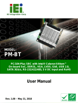
Board Layout: Jumper and Connector Locations
(Unit: mm)
/