OPERATOR’S MANUAL (Original Instructions)
Important! It is essential you read the instructions in this manual before starting and
operating this machine.
Subject to technical modications.
50
46
45
5
47
49
8
48
14
Fig. 7
Fig. 8 Fig. 9
Fig. 6
Fig. 5
Fig. 1
Fig. 4
Fig. 3Fig. 2
17
18
7
54 12
3
10
1
54
51
8
11
13
15
14
9
43
9
42
52
53
9
55
55
1
11
10
12
2
4
5
19
44
8
616
RBCGM25BB

200mm200mm
3.0m 3.0m
200mm200mm
3.0m 3.0m
200mm200mm
3.0m 3.0m
200mm200mm
3.0m 3.0m
200mm200mm
3.0m 3.0m
200mm200mm
3.0m 3.0m
200mm200mm
3.0m 3.0m
200mm200mm
3.0m 3.0m
200mm200mm
3.0m 3.0m
200mm200mm
3.0m 3.0m
2
2
5
5
3
3
6
6
4
4
7
29
30
32
37
41
23
25
40
26
27
39
38
41
37
28
30
29
7
34
36
31
29
33
35
30
31
29
24
Fig. 10
22
21
20
Fig. 11
Fig. 12 Fig. 13
Fig. 14
Fig. 15
1
1
1
2
5
3
6 8
7 9
4
10
11
RBCGM25BB

2
use the product in damp or wet locations.
During carburetor
adjustments the cutting attachment may spin.
Therefore, you should wear protective equipment
and observe all safety instructions when adjusting
the carburetor. For products equipped with a clutch,
be sure the cutting attachment stops turning when the
engine idles. When the product is turned off, make
sure the cutting attachment has stopped before setting
down the product.
Use the product for the
intended purpose only.
Refer to them frequently
and use them to instruct others who may use this
power tool. If you loan someone this power tool, loan
them these instructions also.
Extreme care must be taken when using blades to
ensure safe operation. Read the below specic safety
information on blade use with this machine.
Always hold brushcutter with both hands when
operating. Use a firm grip on both handles.
Maintain your grip and balance on both feet. Position
yourself so that you will not be drawn off balance by
the kick-back reaction of the cutting blade.
Inspect and clear the area of any hidden objects such
as glass, stones, concrete, fencing, wire, wood, metal,
etc.
Never use blades near footpaths, fencing, posts,
buildings or other immovable objects.
Never use a blade after hitting a hard object without
first inspecting it for damage. Do not use if any
damage is detected.
The unit is used as a scythe, cutting from the right to
the left in a broad sweeping action from side to side.
Failure to
follow all instructions may result in serious personal
injury as well as damage to the product.
Do not operate
this product when tired, ill or under the influence of
alcohol, drugs or medication.
Always wear long heavy
pants, boots and gloves. Do not wear loose clothing,
jewellery, short pants, sandals or go barefoot.
Secure hair so that it is above shoulder level to avoid
entanglement in moving parts.
Wear eye
and hearing protection when operating this product.
Before use, inspect the condition of the trimmer.
Replace damaged parts. Check for fuel leaks.
Make sure all fasteners are in place and secure.
Replace cutting attachment parts that are cracked,
chipped or damaged in any way. Make sure the
cutting attachment is properly installed and securely
fastened. Be sure the cutting attachment shield is
properly attached and in the position recommended
by the manufacturer. Use only flexible, non-metallic
line recommended by the manufacturer. For example,
never use wire or wirerope, which can break off and
become a dangerous projectile.
Do
not overreach. Keep the cutting attachment below
waist level. Keep all parts of your body away from the
rotating cutting attachment and hot surfaces.
Never start or run the product inside
a closed room or building; breathing exhaust fumes
can cause illness or death.
Mix and pour fuel outdoors where there are
no sparks and flames. Slowly remove the fuel cap only
after stopping the engine. Do not smoke while fueling
or mixing fuel. Wipe spilled fuel from the product.
Move at least 30ft. (9m) away from the fueling source
and site before starting the engine.
Clear the area to be cut before each use.
Remove all objects, such as rocks, broken glass,
nails, wire or string, that can be thrown or become
entangled in the cutting attachment. Clear the area
of children, bystanders and pets. At a minimum,
keep all children, bystanders and pets outside a 50
ft. (15 m) radius. Because there still may be a risk of
injury to bystanders from thrown objects. Bystanders
should be encouraged to wear eye protection. If you
are approached while operating the product, stop the
engine and the cutting attachment.
To avoid falling, do not

3
The following symbols are located on labels on the attachment shaft. Please study them and learn their meaning. Proper
interpretation of these symbols will allow you to operate the tool better and safer.
Safety Alert Precautions that involve your safety.
Read The Operator’s
Manual
Read the operatorʼs manual before starting or operating this
product. Failure to follow operating instructions and safety
precautions in the operatorʼs manual can result in serious injury.
Eye and Ear Protection
Thrown objects can cause severe eye injury. Wear eye
protection when operating this product.
Wear hearing protection during extended periods of operation.
Thrown Objects Thrown objects can cause severe injury. Wear protective
clothing and boots.
Keep Bystanders Away Keep all bystanders, especially children and pets, at least 50 feet
(15m) from the operating area.
The following signal words and meanings are intended to explain the levels of risk associated with this product.
Indicates an imminently hazardous situation, which, if not
avoided, will result in death or serious injury.
Indicates a potentially hazardous situation, which, if not avoided,
could result in death or serious injury.
Indicates a potentially hazardous situation, which, if not avoided,
may result in minor or moderate injury.
(Without Safety Alert Symbol) Indicates a situation that may
result in property damage.

4
Sound pressure level at operator's ear (in accordance
with EN ISO 22868)
Grass trimmer 98 LWA(dBpA)
Brush cutter 108.1 LWA(dBpA)
Measured sound power level 112.2 LWA(dBpA)
Sound power level (in accordance
with EN ISO 22868) 113 LWA(dBpA)
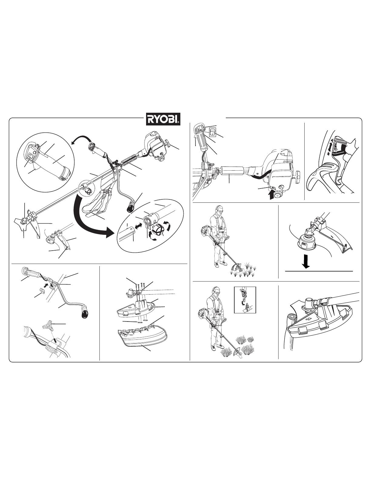
1. Starter grip
2. Strap hanger
3. Left handle
4. Harness
5. Blade guard
6. Tri-arc blade
7. Gear head
8. Upper shaft
9. Throttle trigger
10. Trigger handle
11. On/Off switch
12. Throttle lock out button
13. Cutting line
14. Grass deector
15. Line cut-off blade
16. Knob
17. Coupler
18. Button
51. Guide recess
52. Positioning hole
53. Trimmer attachment
54. Throttle lock on button
55. Foam handle
8. Upper shaft
9. Throttle trigger
19. Bottom clamp
42. Handle bar
43. Top clamp
44. Handle position adjustment knob
5. Blade guard
14. Grass deector
45. Guard screws
46. Guard mounting bracket
47. Threaded mounting plates
48. Slot
Weight without fuel
and trimmer head 5.95 kg
Weight without fuel
with trimmer head 6.02 kg
Weight without fuel
with blade 6.12 kg
Fuel tank volume 620 cm3
Cutting swath 457 mm
Diameter of cutting line 2.4 mm
Engine displacement 25.4 cc
Maximum engine performance
(in accordance with ISO 8893) 0.9 kW
Maximum rotational frequency of
the spindle 10000 min-1
Engine speed (rotational
frequency) at recommended max.
spindle rotational frequency
12000 min-1
Engine speed (rotational
frequency) at idle 2600-3200 min-1
Fuel consumption (in accordance
with ISO 8893) at max. engine
performance
0.54 kg/h
Specific fuel consumption (in
accordance with ISO 8893) at
max. engine performance
0.50 kg/h
Vibration level idling (Trimmer)
Left handle 4.5 m/s2
Right handle 4.1 m/s2
Vibration level racing (Trimmer)
Left handle 4.2 m/s2
Right handle 5.2 m/s2
Vibration level idling (Brush Cutter)
Left handle 3.8 m/s2
Right handle 5.5 m/s2
Vibration level racing (Brush Cutter)
Left handle 3.5 m/s2
Right handle 6.0 m/s2

5
Follow these steps to remove the attachment from the
upper shaft.
1. Loosen the knob by turning it counterclockwise.
2. Push the button while pulling out the attachment.
1. Place the bike handle bar (item 42) in the bottom
clamp (item 19) located on the shaft (item 8) housing.
The throttle trigger (item 9) must be mounted to the
operator's right side.
2. Insert the square tab of top clamp (item 43) into the
mounting hole of the bottom clamp.
3. Adjust the handle bar for best operator control in a
comfortable upright position.
4. Install the knob (item 44) and tighten securely.
1. Attach the blade guard (item 5) to the guard mounting
bracket (item 46); install the four screws (10-24 x 3/4in)
- (Item 45) from the top of the mounting clamp through
the blade guard and into the threaded mounting plates
(item 47).
2. Using the Torx wrench supplied, tighten all four screws
securely.
When using the line trimming head, the grass
deector (item 14) must be attached to the blade guard
(item 5).
1. Carefully align the locking tabs on the grass deector
(item 49) with the the slots on the blade guard (item
48).
2. Push the grass deector towards the blade guard until
the locking tabs click rmly into place.
The grass deector is tted with a line cut off blade.
Take extra care when tting the grass deector to avoid
contact with the sharp blade.
1. Stop the engine and disconnect the spark plug wire.
2. Remove currently installed line trimmer head or cutting
blade.
3. Open the Reel Easy Line Trimmer Head by depressing
the latches on each side. The contents of the line
trimmer head are spring loaded, so keep your
other hand over the line trimmer head cover while
depressing the latches. (image 3)
4. Remove the line trimmer head cover, bump knob, and
line spool and set aside.
49. Locking tabs
1. Starter grip
9. Throttle trigger
10. Trigger handle
11. On/Off switch
12. Throttle lock out button
50. Primer bulb
54. Throttle lock on button
55. Foam handle
20. Foam air lter
21. Air lter cover
22. Cover securing knob
23. Spark plug boot
24. Spark plug
25. Spark arrestor
26. Bump head spring
27. Bump head securing bolt
28. Cutting head housing
29. Blade ange washer
30. Gearbox
31. Shaft locking pin
32. Socket wrench
33. Cupped washer
34. Blade nut
35. Blade
36. Spanner
37. Gear shaft
38. Bump head cover
39. Bump knob
40. Line spool
41. Drive shaft adaptor
Follow these steps to connect the attachment to the upper
shaft (item 8).
1. Loosen the knob (item 16) by turning it counter
clockwise.
2. Align the button (item 18) on the attachment shaft with
the guide recess (item 51) on the upper shaft.
3. Slide the attachment shaft into the upper shaft until the
attachment shaft clicks into place.
4. Tighten the knob securely by turning it clockwise.

6
5. Place the cutting head housing on the drive shaft.
Make sure the housing is fully seated.
6. Install the hex bolt to secure the line trimmer head
to the drive shaft. Tighten by using the hex-shaped
opening on the inside of the bump knob.
7. Only use the bump knob to tighten the bolt. The
use of other tools may allow over tightening of the bolt,
which could damage the line trimmer head. (image 4)
8. Reinstall the bump head spring into the line trimmer
head and push down to seat. (image 5)
9. Reinstall the line spool.
10. For the straight shaft attachment with the Reel
Easy cutting head, the spool should be placed so “This
side out for straight shaft” is visible on the line spool.
11. Replace the bump knob by inserting it into the centre
of the line spool.
12. Replace the line trimmer head cover, aligning latches
with openings in the line trimmer head. Press cover
and line trimmer head together until both latches snap
into openings securely.
13. Install line as described in the next section of this
manual.
Use 2.4mm diameter monolament line.
1. Stop the engine and disconnect the spark plug wire.
2. Cut one piece of line approximately 6.0m in length.
3. Rotate the bump knob on line trimmer head until line
on the centre of the bump knob aligns with arrows on
top of line trimmer head. (image 6)
4. Insert one end of line into eyelet located on the side
of the line trimmer head and push until line comes out
through the eyelet on the other side. Continue to push
line through the line trimmer head until the middle
section of the line is inside the line trimmer head and
line outside the line trimmer head is evenly divided on
each side. (images 7-8)
5. Rotate the knob on the line trimmer head to wind the
line. If using a straight shaft attachment, the knob
should be rotated clockwise.
6. Wind the line until approximately 20cm remains
protruding from the line trimmer head.
7. Replace the spark plug boot.
Stop the engine and disconnect the spark plug wire.
1. Open the Reel Easy Line Trimmer Head by depressing
the latches on each side. The contents of the line
trimmer head are spring loaded, so keep your
other hand over the line trimmer head cover while
depressing the latches.
2. Remove the bump head cover (item 38), bump knob
(item 39), line spool (item 40) and spring (item 26) and
set them aside.
3. Use the hex-shaped opening on the inside of the
bump knob (item 39) to remove the hex bolt (item 27)
from the drive shaft adaptor (item 41) in a clockwise
direction and set aside.
4. Remove the cutting head housing (item 28).
5. Align the slot in the upper ange washer (item 29) with
the hole in the gear head (item 30). Insert the holding
pin (item 31) through the slot in the upper ange
washer and the hole in the gear head. Using the 16mm
socket wrench (item 32) supplied, turn the drive shaft
adaptor (item 41) clockwise to remove it from the gear
shaft (item 37). Remove the upper ange washer from
the gear shaft and retain for blade installation. (Fig. 14
images 4-5)
6. Remove the grass deector by pushing in on the three
locking tabs while pulling on the grass deector to
separate from the blade guard. (image 6)
Store the line trimmer head parts and grass
deflector together for later use.
1. Place the upper ange washer (item 29) over the gear
shaft with the hollow side towards the blade guard.
2. Centre blade (item 35) on the upper ange washer,
making sure the blade sits at. Install the cupped
washer (item 33) with the raised centre away from
the blade. Install and hand tighten the blade nut in
a counterclockwise direction (item 34). The blade
(item 35) turns counterclockwise from the operator’s
position during operation.
3. Insert the holding pin through the slot in the upper
ange washer and the hole in the gear head (item 30).
Using the wrench (item 36) supplied, turn the blade nut
(item 34) counterclockwise.
4. Tighten nut securely.
1. Insert the holding pin through the slot in the upper
ange washer and the gear head. Turn the blade nut
clockwise to remove.
2. Remove the cupped washer and the blade.
3. Remove the upper ange washer from the gear shaft
and retain for the line trimmer head installation.
4. Attach the grass deector to the blade guard. Refer
to "ATTACHING THE GRASS DEFLECTOR TO THE
GUARD" earlier in this manual.
Store the brush cutter parts together for later
use.

7
Always handle fuel with care, it is highly flammable.
Always refuel outdoors where there are no sparks and
flames. Do not inhale fuel vapors.
Do not let petrol or oil come in contact with your skin.
Keep petrol and oil away from the eyes. If petrol
or oil comes in contact with the eyes, wash them
immediately with clean water. If irritation is still present,
see a doctor immediately.
Clean up spilled petrol immediately.
This product is powered by a 2-stroke engine and
requires pre-mixing petrol and 2-stroke oil. Pre-mix
unleaded petrol and 2-stroke engine oil in a clean
container approved for petrol.
This engine is certified to operate on unleaded petrol
intended for automotive use with an octane rating of
87 ([R + M] / 2) or higher.
Do not use any type of pre-mixed petrol / oil from fuel
service stations, this includes the pre-mixed petrol / oil
intended for use in mopeds, motorcycles, etc.
Use synthetic 2-stroke oil only. Do not use automotive
oil or 2-stroke outboard oil.
Mix 2% synthetic 2-stroke oil into the petrol. This is a
50:1 ratio.
Mix the fuel thoroughly and also each time before
fueling.
Mix in small quantities. Do not mix quantities larger
than usable in a 30 day period. Synthetic 2-stroke oil
containing a fuel stabilizer is recommended.
1. Clean surface around fuel cap to prevent
contamination.
2. Loosen fuel cap slowly to release pressure and to
keep fuel from escaping around the cap.
3. Carefully pour fuel mixture into the tank. Avoid spillage.
4. Prior to replacing the fuel cap, clean and inspect the
gasket.
5. Immediately replace fuel cap and hand tighten. Wipe
up any fuel spillage. Move 9 m away from refueling site
before starting engine.
It is normal for smoke to be emitted from a new
engine during and after rst use.
Always shut off engine before fueling. Never add fuel to
a machine with a running or hot engine. Move at least
9m from refueling site before starting engine. Do not
smoke!
1 litre + 20 ml =
2 litres + 40 ml =
3 litres + 60 ml = 50: 1 (2%)
4 litres + 80 ml =
5 litres + 100 ml =
Prior to starting the brushcutter, clear the area of
children, bystanders and pets.
The product may throw objects during starting
and operation, causing injury to the operator or to
bystanders. Always wear suitable eye protection, long
pants and heavy boots while operating the product. Do
not start the trimmer on gravel surfaces.
Starting the product differs depending on whether the
engine is cold or warm. Refer to the label on the air lter
cover.
Follow these steps to start a cold engine.
1. Lay the product on a at, bare surface.
2. Ensure the engine switch is in the I (ON) position (item
11).
3. Push the primer bulb (item 50) approximately 10 times.
4. Set the choke lever to position A (choke closed).
5. Hold down the throttle lock out button (item 12) and
squeeze the throttle trigger (item 9). Lock throttle in
position by depressing the throttle lock on button (item
54).
6. Hold the foam handle (item 55) tight with left hand, and
with the right hand pull the starter grip (item 1) with
a quick rm and consistent upward motion (no more
than 4x).
7. Set the choke lever to position B (choke open).
8. Pull the starter grip with a quick rm and consistent
upward motion until the engine starts (no more than
6x).

8
9. When the engine starts, squeeze the throttle trigger to
release the lock. You may need to feather the throttle
until the engine will idle on its own. Allow engine to
warm up for 30 seconds prior to operation.
If engine does not start, return to step 4 and repeat
the steps.
Follow these steps to start a warm engine.
1. Lay the product on a at, bare surface.
2. Ensure the engine switch is in the I (ON) position (item
11).
3. Ensure the choke lever is set to position B (Choke
Open).
4. Hold down the throttle lock out button (item 12) and
squeeze the throttle trigger (item 9). Lock throttle in
position by depressing the throttle lock on button (item
54).
5. Hold the foam handle (item 55) tight with left hand, and
with the right hand pull the starter grip (item 1) with
a quick rm and consistent upward motion (no more
than 6x).
6. When the engine starts, squeeze the throttle trigger to
release the lock.
If engine does not start, return to step 4 of "TO
START A COLD ENGINE" and repeat the steps.
1. Release the throttle trigger.
2. Hold down the engine switch to the O (OFF) position
until the engine comes to a complete stop.
Follow these steps to operate the straight shaft trimmer.
1. Start the trimmer.
2. Hold the trimmer at waist level with your right hand
on the trigger handle and your left hand on the front
handle.
3. Place the product on the right side of your body with
the engine behind and away from your body.
4. Trim grass and weeds in a left-to-right motion with the
line parallel to the ground.
Follow these steps to advance the cutting line.
1. Start the trimmer.
2. Tap the bump knob lightly on the ground while the
motor is running. The line will only advance with the
engine at full throttle. Do not hold the bump knob on
the ground.
The line cutting blade on the safety guard will
cut the line to the proper length.
To help prevent line tangle, tap only once to
lengthen the line. If additional line is required, wait a
few seconds before retapping the bump knob. Do not
allow the line to wear too short. Keep the cutting line
at full length.
Extreme care must be taken when using blades to
ensure safe operation. Read “Specic Safety Rules for
Brushcutter and Blade Use” earlier in this manual.
The TRI-ARC blade is suitable only for pulpy weeds and
vines. When the blade becomes dull, it can be turned over
to extend the life of the blade. Do not sharpen the TRI-
ARC blade.
Hold the brushcutter with the right hand on the trigger
handle and the left hand on the front handle. Keep a rm
grip with both hands while in operation. Brushcutter should
be held at a comfortable position with the trigger handle
about hip height. Maintain your grip and balance on both
feet. Position yourself so that you will not be drawn off
balance by the kick-back reaction of the cutting blade. If
using a shoulder strap or harness, adjust to position the
brushcutter at a comfortable operating position.
Exercise extreme caution when using the blade with this
unit. Blade thrust is the reaction which may occur when
the spinning blade contacts anything it cannot cut. This
contact may cause the blade to stop for an instant, and
suddenly “thrust” the unit away from the object that was
hit. This reaction can be violent enough to cause the
operator to lose control of the unit. Blade thrust may occur
without warning if the blade snags, stalls or binds. This is
more likely to occur in areas where it is difcult to see the
material being cut. For cutting ease and safety, approach
the weeds being cut from the right to the left. In the event
that an unexpected object or woody stock is encountered,
this could cause the blade thrust reaction.
When servicing, use only identical replacement parts.
Use of any other parts may create a hazard or cause
product damage.
Always wear safety goggles or safety glasses with side
shields during tool operation. If operation is dusty, also
wear a dust mask.

9
Before inspecting, cleaning, or servicing the machine,
shut off engine, wait for all moving parts to stop, and
disconnect spark plug lead and move it away from
spark plug. Failure to follow these instructions can
result in serious personal injury or property damage.
Neglected or poorly conducted maintenance may
create additional hazards. Do not attempt to repair or
maintain this product if you are not qualied to do so.
If in doubt, return to a service centre for professional
assistance.
Avoid using solvents when cleaning plastic parts. Most
plastics are susceptible to damage from various types of
commercial solvents and may be damaged by their use.
Use clean cloths to remove dirt, dust, lubricant, grease.
Do not at any time let brake uids, petrol, petroleum-
based products, penetrating lubricants, etc., come
in contact with plastic parts. Chemicals can damage,
weaken or destroy plastic which may result in serious
personal injury.
You can often make adjustments and repairs described in
this manual. For other repairs, have the trimmer serviced
by an authorised service dealer.
A dirty air lter will cause starting difculty, loss of
performance, and shorten the life span of the engine.
Check the air lter monthly. For best performance, replace
the air lter at least once a year.
1. Loosen the air lter cover by turning the cover securing
knob (item 22) counterclockwise.
2. Remove the air lter (item 20).
3. Clean the foam lter element with warm soapy water.
Rinse and let dry.
If the foam lter element is damaged, it should be
replaced.
4. Apply a light coat of engine oil to the foam lter
element, then squeeze it out.
5. Reinstall the air lter.
Make sure the lter is seated properly inside the
cover. Installing the lter incorrectly will allow dirt to enter
the engine, causing rapid engine wear.
6. Reinstall the cover and tighten knob to secure.
A leaking fuel cap is a re hazard and must be replaced
immediately.
The fuel cap contains a non-serviceable lter and
check valve. A clogged fuel lter causes poor engine
performance. If performance improves when the fuel cap
is loosened, the check valve may be faulty or the lter may
be clogged. Replace the fuel cap if necessary.
This engine uses a Champion RCJ6Y or NGK BPMR7A
spark plug. Use an exact replacement and replace
annually.
Follow these steps to replace the spark plug.
1. Remove the spark plug boot (item 23).
2. Loosen the spark plug (item 24) by turning it
counterclockwise with a 16mm socket.
3. Remove the spark plug.
4. Hand thread the new spark plug, turning it clockwise.
5. Tighten with a socket. Do not overtighten.
Be careful not to cross-thread the spark plug. Cross-
threading will seriously damage the engine.
Follow these steps to clean the spark arrestor.
1. Locate the spark arrestor (item 25) through the hole on
the mufer exit hole.
2. Remove the spark arrestor using needle-nosed pliers.
3. Clean the spark arrestor with a small wire brush.
4. Replace the spark arrestor.
Storing the product differs depending on the duration it will
be in storage.
Follow these steps for short term product storage.
1. Clean all foreign material from the product.
2. Store the product in a well-ventilated place that is
inaccessible to children.
If you do not intend to use the product for more than one
month, follow the storage procedures below.
1. Drain all fuel from the tank into a container approved
for petrol.
2. Run the engine until it stops.
3. Clean all foreign material from the product.
4. Store the product in a well-ventilated place that is
inaccessible to children.
Keep the product away from corrosive agents

10
such as garden chemicals.
Abide by all local and government
regulations for the safe storage and handling of petrol.

11
Engine will not start
1. Switch set to the O (OFF) position. 1. Set switch to the I (ON) position.
2. No spark
2. Remove the spark plug. Re-attach the spark plug
cap and lay the spark plug on the metal cylinder.
Pull the starter cord and watch for a spark at the
spark plug tip. If there is no spark, repeat the test
with a new spark plug.
3. No fuel 3. Push primer bulb until the bulb is full of fuel. If the
bulb does not ll, the primary fuel delivery system
is blocked. If the primer bulb lls, the engine may
be ooded. (See next item.)
4. Flooded engine
4. Remove the spark plug. Turn the product so that
the spark plug hole is aimed at the ground. Make
sure the choke lever is set to position B and pull
the starter cord 10 to 14 times. This clears excess
fuel from the engine. Clean and reinstall the spark
plug. With the throttle trigger fully depressed, pull
the starter cord 3 times. If the engine does not
start, set the choke lever to A and follow normal
starting instructions. If the engine still fails to start,
repeat the procedure with a new spark plug.
5. Starter cord is hard to pull
5. Contact an authorized service dealer.
Engine does not reach full speed
and emits excessive smoke
1. Incorrect oil/fuel mixture 1. Use fresh fuel and the correct 2-stroke oil mix.
2. Air filter is dirty 2. Clean the air filter according to the instructions in
the Maintenance section.
3. Spark arrestor screen is dirty 3. Contact an authorized service dealer.
Cutting line will not advance when
using bump feed action
1. Line welded to itself 1. Lubricate with silicone spray.
2. Not enough line on the spool 2. Install more line.
3. Line worn too short 3. Pull line while alternately pressing down on and
releasing the bump knob.
4. Line tangled on spool 4. Remove line from spool and rewind.
5. Engine speed too slow 5. Advance line at full throttle.
6. Line spool installed back to front
6. Ensure the writing on the line spool is facing the
correct way; THIS SIDE OUT FOR STRAIGHT
SHAFT.
Grass wraps around the trimmer
head assembly and the attachment
shaft
1. Cutting tall grass at ground level 1. Cut tall grass from the top down.
2. Operating the product at part throttle 2. Operate the product at full throttle.
Oil drips from muffler
1. Operating the product at part throttle 1. Operate the product at full throttle.
2. Incorrect oil/fuel mixture 2. Use fresh fuel and the correct 2-stroke oil mix.
3. Air filter is dirty 3. Clean the air filter according to the instructions in
the Maintenance section.

TECHTRONIC INDUSTRIES (AUSTRALIA) PTY. LTD.
Level 1, 660 Doncaster Road,
Doncaster, Victoria 3108,
Australia
Tel: 1300 361 505 Fax: 1800 807 993
TECHTRONIC INDUSTRIES N.Z. LIMITED
Auckland: 27 Clemow Drive, Mt Wellington, N.Z.
Tel: (09) 573 0230 Free Call: 0800 279 624 Fax: (09) 573 0231
Contact during normal business hours.
Subject to the guarantee condition below, this Ryobi
tool (hereinafter called “the product”) is guaranteed by
TECHTRONIC INDUSTRIES AUSTRALIA PTY
LIMITED (hereinafter called “the Company”) to be free
from defects in material or workmanship for a period
of 24 months from the date of original purchase
covering both parts and labour. Under the terms of
this guarantee, the repair or replacement of any part
shall be the opinion of the Company or its authorised
service centre. Should service become necessary
during the warranty period, the owner should contact
the customer service HELPLINE 1300 361 505 or
contact the retailer from whom the product was
purchased.
In order to obtain guarantee service, the owner must
present the sales docket and Guarantee Certificate to
confirm date of purchase. This product is sold by the
dealer or service centre as principal and the dealer
has no authority from the Company’s behalf except as
herein contained or herein referred to.
Guarantee Conditions
This guarantee only applies provided that the product
has been used in accordance with the manufacturer’s
recommendations under normal use and reasonable
care (in the opinion of the Company) and such
guarantee does not cover damage, malfunction or
failure resulting from misuse, neglect, abuse, or used
for a purpose for which it was not designed or is not
suited and no repairs, alterations or modifications
have been attempted by other than an authorised
service centre. This guarantee will not apply if the tool
is damaged by accident or if repairs arise from normal
wear and tear. The Company accepts no additional
liability pursuant to this guarantee for the costs of
travelling or transportation of the product or parts to
and from the service dealer or service centre - such
costs are not included in this guarantee.
Certain legislation, including the Trade Practices Act,
1974 (as amended) and other state and territorial laws
give rights to the buyer and impose liability on the
seller in certain circumstances. Nothing herein shall
have the effect of excluding, restricting or modifying
any condition, guarantee, right or liability imposed, to
the extent only that such exclusion, restriction or
modification would render any term herein void.
/