Alto-Shaam 1000-S Series Installation, Operation and Maintenance Manual

Category
Thermostats
Type
Installation, Operation and Maintenance Manual

This manual is also suitable for

#823/32/36 • 4/2005
PRINTED IN U. S . A .
INSTALLATION
OPERATION
AND
MAINTENANCE
MANUAL
FOOD
HOLDING
CABINET
Manual or Electronic
Control
MODELS:
500-S
750-S
1000-S
W164 N9221 Water Street P.O. Box 450 Menomonee Falls, Wisconsin 53052-0450 U.S.A.
PHONE: 262.251.3800 FAX: 262.251.7067 • 800.329.8744 U.S.A. ONLY WEBSITE:
800.558-8744 USA/CANADA 262.251.1907 INTERNATIONAL www.alto-shaam.com
Manual Control
Electronic Control
500-S
750-S
1000-S
with Manual Control
and casters
The Alto-Shaam Holding Cabinet has
been thoroughly tested, checked for
calibration, and inspected to insure only
the highest quality cabinet is provided.
When you receive your cabinet, check for
any possible shipping damage and report
it at once to the delivering carrier.
See
Transportation Damage and Claims
section located in this manual.
The cabinet, complete with unattached items and
accessories, may be delivered in one or more packages.
Check to ensure that the following items have been
received as standard with each unit.
500-S 2: SIDE RACKS 2: WIRE SHELVES
750-S 2: SIDE RACKS 3: WIRE SHELVES
1000-S 2: SIDE RACKS 4: CASTERS
Save all the information and instructions packed
inside the cabinet. Complete and return the warranty
card to the factory as soon as possible to assure prompt
service in the event of a warranty parts and labor claim.
Alto-Shaam holding cabinets are designed for the
purpose of maintaining hot food at a temperature for
safe consumption. The unit must be installed in a
location that will permit the equipment to function for its
intended purpose and allow adequate access for proper
cleaning and maintenance. Installation minimum
clearance recommendations are: 3-inches (76mm) at the
back, 2-inches (51mm) at the top, and 1-inch (25mm) at
both sides.
NOTE: All claims for warranty must include the full
model number and serial number of the cabinet.
The cabinet is equipped with a special heating cable.
Through this Halo Heat concept, the heating cable is
mounted against the walls of the unit to provide an
evenly applied heat source controlled by a thermostat.
The design and operational characteristics of the unit
eliminate the need for a moisture pan or a heat
circulating fan. Through even heat application,
the quality of food products is maintained up to several
hours or more.
1. An identification tag is permanently mounted on
the cabinet.
2. Plug cabinet into a properly grounded receptacle
ONLY, positioning the unit so the power supply
cord is easily accessible in case of an emergency.
3. If necessary, a proper receptacle or outlet
configuration as required for this unit,
must be installed by a licensed electrician
in accordance with applicable, local electrical codes.
For 230V units:
To prevent an electrical shock hazard
between the appliance and other appliances or metal
parts in close vicinity, an equalization-bonding stud is
provided. An equalization bonding lead must be
connected to this stud and the other appliances /
metal parts to provide sufficient protection against
potential difference. The terminal is marked with the
following symbol. NOTE
: The appliance must
be connected to an electrical circuit that is protected
by an external GFCI outlet.
#823/32/36 INSTALLATION/OPERATION/SERVICE MANUAL • 1.
HOLDING CABINETS
®
UNPACKING and SET-UP ELECTRICAL INSTALLATION
®
®
PATENT NOS.
3521030
4595247
®
PH
ENSURE POWER SOURCE
MATCHES VOLTAGE S TAMPED
ON NAMEPLATE OF UNIT
HEATING CHARACTERISTICS
Disconnect unit from power source
before cleaning or servicing.
At no time should the inside or
outside of the cabinet be washed
down, flooded with water or liquid
solution
. Do not clean with water jet.
NEVER STEAM CLEAN.
Severe damage or electrical
hazard could result.
Warranty becomes void
if unit is flooded.
1. The unit should be installed level and should NOT be installed in any area where it may be affected by steam,
grease, dripping water, high temperatures or any other severely adverse conditions.
2. Before operating the cabinet, clean both the interior and exterior of the unit with a damp, clean cloth and
mild soap solution. Rinse carefully.
3. Clean and install the cabinet side racks. Shelves should be positioned with the curved end up and toward the
back of the unit.
4. Before operating the unit, become familiar with the operation of the controls. Read this manual and keep it
in a secure location.
START-UP
#823/32/36 INSTALLATION/OPERATION/SERVICE MANUAL 2.
INSTALLATION
39-7/8" (1013mm)
17-5/8" (447mm)
25-7/16" (646mm)
500-S
500-S/PT
500-S/TM
57-1/2" (1461mm)
27-9/16" (700mm)
33-11/16" (855mm)
22-1/4" (565mm)
3-3/8" (86mm)
6-1/32" (153mm)
for 5" casters or
6" legs
65-3/4" (1670mm) MAXIMUM
19-5/16"
(491mm)
C
L
REACH-IN
Electrical
Connection
1-7/8" (48mm)
from top
C
L
PASS-THROUGH
Bumper, Full-perimeter Rubber Assembly with Stem Casters . . . . . . . . . . .44094
Carrying Handle Kit . . . . . . . . . . . . . . . . . . . . . . . . . . . . . . . . . . . . . . .55662
Carving Holder
Prime Rib Holder . . . . . . . . . . . . . . . . . . . . . . . . . . . . . . . . . . . . .HL-2635
Casters, 3" (76mm) . . . . . . . . . . . . . . . . . . . . . . . . . . . . . . . . . . . . . . . .14227
Casters, 5" (127mm) . . . . . . . . . . . . . . . . . . . . . . . . . . . . . . . . . . . . . . . .4007
Drip Pan . . . . . . . . . . . . . . . . . . . . . . . . . . . . . . . . . . . . . . . . . . . . .PN-2122
Drip Tray - External . . . . . . . . . . . . . . . . . . . . . . . . . . . . . . . . . . . . . . . .4018
Legs, 6" (152mm) . . . . . . . . . . . . . . . . . . . . . . . . . . . . . . . . . . . . . . . . . .5205
Security Panel Package . . . . . . . . . . . . . . . . . . . . . . . . . . . . . . . . . . .5002181
Shelf
Chrome Wire . . . . . . . . . . . . . . . . . . . . . . . . . . . . . . . . . . . . . . . .SH-2107
Stainless Steel Wire . . . . . . . . . . . . . . . . . . . . . . . . . . . . . . . . . . . .SH-2326
Stacking Kit
500-S on top of 500-S . . . . . . . . . . . . . . . . . . . . . . . . . . . . . . . .5001359
500-S on top of 500-TH/II . . . . . . . . . . . . . . . . . . . . . . . . . . . . .5001359
500-S on top of 500-TH/III . . . . . . . . . . . . . . . . . . . . . . . . . . . .5001359
500-TH/II on top of 500-S . . . . . . . . . . . . . . . . . . . . . . . . . . . . .5001359
500-TH/III on top of 500-S . . . . . . . . . . . . . . . . . . . . . . . . . . . .5000811
TMS Carvery on top of 500-S . . . . . . . . . . . . . . . . . . . . . . . . . . . . .16222
HACCP Network Options (Electronic Control Only)
Control Option Kit . . . . . . . . . . . . . . . . . . . . . . . . . . . . . . .5000886
HACCP Documentation . . . . . . . . . . . . . . . . . . . . . . . . . . .5001640
HACCP with Kitchen Management . . . . . . . . . . . . . . . . . . .5001458
Options & Accessories
500-S
Exterior Dimensions
#823/32/36 INSTALLATION/OPERATION/SERVICE MANUAL 3.
WHEN MOUNTING DRIP TRAY,
SEAL DRIP TRAY HOLDER TO
UNIT WITH AN R.T.V. SEALANT
DRIP TRAY
DRIP TRAY HOLDER
OPTIONAL DRIP TRAY MOUNTING INSTRUCTIONS
MODELS:
W164 N9221 Water Street P. O. Box 450
Menomonee Falls, Wisconsin 53052-0450
EXTERNAL DRIP TRAY PACKAGE: #4018
500-S OPTIONAL
For on-site installation of the external drip tray, it is
necessary to drill and tap 3 holes in the cabinet as
shown on the above drawing. Use a 8 — 32 tap, 1/8" drill bit or #30 bit.
[Bottom of oven interior Below side-racks]
OPTIONAL DRIP PAN
®
3: 8 — 32 x 1/2" SCREWS
[A/S PN: SC-2425]
INSTALLATION
#823/32/36 INSTALLATION/OPERATION/SERVICE MANUAL 4.
INSTALLATION
Stacking Instructions
No. 16222 or 16237 kit for
750-S
Using Stacking Platform from
kits 16222 or 16237
to provide carving shelf:
1. Remove the three screws in the top plate at the
front of the cabinet.
2. Remove the three screws in the back plate near the
top of the cabinet.
2. Position the stacking platform on top of the unit
with the flange in front, aligning the holes in the
platform over the holes in the cabinet.
3. Reinstall the cabinet screws removed in steps 1 and 2
through the platform holes to attach it to the cabinet,
front and back.
4. Place the carvery shelf on the stacking platform.
500-S or
stacking carving shelf
Step 1
Step 2
#823/32/36 INSTALLATION/OPERATION/SERVICE MANUAL 5.
INSTALLATION
Stacking Instructions
STACKING PLATE INSTALLATION
Kit #5001359
1. Measure the length and width of the top surface of the
cabinet to be positioned at the bottom of the stacking
equipment combination. Add 1/8-inch to both the length
and the width dimension.
2. Turn the cabinet to be placed at the top of the stacking
combination upside down so that the top surface is on the
floor. Remove the eight (8) bolts located at the front (door
side) and at the rear of the cabinet. Replace the bolts with
the eight (8) nylon plugs provided in the stacking kit (RI-
26196).
3. Place the four (4) stacking plates at each corner of the
cabinet. Position the plates with the upright flange
pointing up and to the outside of the cabinet. Align the
holes in the stacking plates with the predrilled holes in the
bottom of the cabinet using both the length and width
dimensions obtained in step 1.
4. When the correct alignment has been achieved, loosely
fasten each stacking plate with four (4) screws provided in
the stacking kit. DO NOT TIGHTEN SECURELY since
minor adjustments may be necessary.
5. Stack the cabinets and make any necessary minor
adjustments to the stacking plates. When properly aligned,
the door on the top cabinet should be flush with the door
on the bottom cabinet.
6. When proper alignment has been made, remove the top
cabinet from the stacking combination. Firmly secure all
four stacking plates by individually removing each screw
and reattaching it in combination with one of the square
washers provided in the stacking kit.
Step 2 above.
Steps 3 and 4
above.
Depth
Width
Stacking
Plate
#823/32/36 INSTALLATION/OPERATION/SERVICE MANUAL 6.
Bumper, Full-perimeter Rubber Assembly with Stem Casters . . . . . . . . . . .44107
Door with window . . . . . . . . . . . . . . . . . . . . . . . . . . . . . . . . . . . . . . . . .55609
Drip Tray - External . . . . . . . . . . . . . . . . . . . . . . . . . . . . . . . . . . . . . . . .4020
Carrying Handle Kit. . . . . . . . . . . . . . . . . . . . . . . . . . . . . . . . . . . . . . . .55662
Carving Holder
Prime Rib Holder . . . . . . . . . . . . . . . . . . . . . . . . . . . . . . . . . . . . .HL-2635
Ship Round Holder . . . . . . . . . . . . . . . . . . . . . . . . . . . . . . . . . . . . . . .4459
Casters, 3" (76mm) . . . . . . . . . . . . . . . . . . . . . . . . . . . . . . . . . . . . . . . .14227
Casters, 5" (127mm) . . . . . . . . . . . . . . . . . . . . . . . . . . . . . . . . . . . . . . . .4007
Drip Pan . . . . . . . . . . . . . . . . . . . . . . . . . . . . . . . . . . . . . . . . . . . . . . . .1062
Drip Tray - External . . . . . . . . . . . . . . . . . . . . . . . . . . . . . . . . . . . . . . . .4020
Legs, 6" (152mm) . . . . . . . . . . . . . . . . . . . . . . . . . . . . . . . . . . . . . . . . . .5205
Security Panel Package . . . . . . . . . . . . . . . . . . . . . . . . . . . . . . . . . . .5002180
Shelf
Chrome Plated Wire, Flat . . . . . . . . . . . . . . . . . . . . . . . . . . . . . . . .SH-2105
Chrome Plated Wire, Lip . . . . . . . . . . . . . . . . . . . . . . . . . . . . . . . .SH-2327
Stainless Steel Wire . . . . . . . . . . . . . . . . . . . . . . . . . . . . . . . . . . . .SH-2324
Transport Handle Package . . . . . . . . . . . . . . . . . . . . . . . . . . . . . . . . . . .55575
Stacking Kit
750-S on top of 750-S . . . . . . . . . . . . . . . . . . . . . . . . . . . . . . . .5001359
750-S on top of 750-TH/II . . . . . . . . . . . . . . . . . . . . . . . . . . . . .5001359
750-S on top of 750-TH/III . . . . . . . . . . . . . . . . . . . . . . . . . . . .5001359
750-TH/II on top of 750-S . . . . . . . . . . . . . . . . . . . . . . . . . . . . .5001359
750-TH/III on top of 750-S . . . . . . . . . . . . . . . . . . . . . . . . . . . .5000811
BCS carvery on top of 750-S . . . . . . . . . . . . . . . . . . . . . . . . . . . . .16237
HACCP Network Options (Electronic Control Only)
Control Option Kit . . . . . . . . . . . . . . . . . . . . . . . . . . . . . . .5000886
HACCP Documentation . . . . . . . . . . . . . . . . . . . . . . . . . . .5001640
HACCP with Kitchen Management . . . . . . . . . . . . . . . . . . .5001458
INSTALLATION
27-1/8" (689mm)
30-1/2" (775mm)
25-1/2" (648mm)
32-7/16" (849mm)
65-3/8" (1661mm)
52-1/2" (1334mm)
77-11/16" (1973mm)
1-15/16" (49mm)
28-1/8" (714mm)
6-3/16" (157mm)
for 5" casters or
6" legs
C
L
REACH-IN
Electrical
Connection
1-15/16" (49mm)
from top
PASS-THROUGH
CORD LOCATION
13" (330mm)
3-3/8" (86mm)
Options & Accessories
750-S
Exterior
Dimensions
#823/32/36 INSTALLATION/OPERATION/SERVICE MANUAL 7.
WHEN MOUNTING DRIP TRAY,
SEAL DRIP TRAY HOLDER TO
UNIT WITH AN R.T.V. SEALANT
DRIP TRAY
DRIP TRAY HOLDER
DRIP TRAY MOUNTING INSTRUCTIONS
MODEL:
W164 N9221 Water Street P. O. Box 450
Menomonee Falls, Wisconsin 53052-0450
EXTERNAL DRIP TRAY PACKAGE: #4020
750-S OPTIONAL
For on-site installation of the external drip tray, it is
necessary to drill and tap 3 holes in the cabinet as
shown on the above drawing. Use an 8 32 tap, 1/8" bit drill or #30 bit.
[Bottom of oven interior Below side-racks]
OPTIONAL DRIP PAN
®
3: 8 32 x 1/2" SCREWS
[A/S PN: SC-2425]
INSTALLATION
#823/32/36 INSTALLATION/OPERATION/SERVICE MANUAL 8.
INSTALLATION
Bumper, Full-perimeter Rubber Assembly with Stem Casters . . . . . . . . . . .44119
Carrying Handle Kit . . . . . . . . . . . . . . . . . . . . . . . . . . . . . . . . . . . . . . .55662
Casters, 3" (76mm) . . . . . . . . . . . . . . . . . . . . . . . . . . . . . . . . . . . . . . . .14227
Door, Window . . . . . . . . . . . . . . . . . . . . . . . . . . . . . . . . . . . . . . . . . . .15148
Legs, 6" (152mm) . . . . . . . . . . . . . . . . . . . . . . . . . . . . . . . . . . . . . . . . . .5205
Pan Grid, Chrome, Wire
18" x 26" Pan Insert . . . . . . . . . . . . . . . . . . . . . . . . . . . . . . . . . . .PN-2115
Security Panel Package . . . . . . . . . . . . . . . . . . . . . . . . . . . . . . . . . . .5002182
Shelf, Stainless Steel Wire
Reach-In . . . . . . . . . . . . . . . . . . . . . . . . . . . . . . . . . . . . . . . . . . . .SH-2325
Pass-Through . . . . . . . . . . . . . . . . . . . . . . . . . . . . . . . . . . . . . . . .SH-2346
Stacking Kit, cabinets . . . . . . . . . . . . . . . . . . . . . . . . . . . . . . . . . . . .5001359
Options & Accessories
49-1/2" (1258mm)
1000-S
71-3/4" (1823mm)
36-1/8" (918mm)
29-1/4" (743mm)
1-3/4" (44mm)
22" (559mm)
C
L
REACH-IN
Electrical
Connection
2-7/8" (73mm)
from top
C
L
PASS-THROUGH
5-5/8" (143mm)
PASS-THROUGH ELECTRICAL CONNECTION
33-1/4" (845mm)
41-3/4" (1060mm)
30-5/8" (778mm)
(PASS- THROUGH)
HACCP Network Options (Electronic Control Only)
Control Option Kit . . . . . . . . . . . . . . . . . . . . . . . . . . . . . . .5000886
HACCP Documentation . . . . . . . . . . . . . . . . . . . . . . . . . . .5001640
HACCP with Kitchen Management . . . . . . . . . . . . . . . . . . .5001458
1000-S
Exterior Dimensions
#823/32/36 INSTALLATION/OPERATION/SERVICE MANUAL 9.
OPERATION - MANUAL CONTROL
1. Preheat at 200°F (93°C) for 30 minutes.
When the thermostat is turned clockwise to the ON
position, the indicator light will illuminate and will
remain lit as long as the unit is calling for heat.
Allow a minimum of 30 minutes of preheating before
loading the holding cabinet with food. Closing the
vents on the inside of the door will speed up the
process. The indicator light will go OUT after
approximately 30 minutes, or when the air
temperature inside the unit reaches the temperature
set by the operator.
2. Load the cabinet with hot food only.
The purpose of the holding cabinet is to maintain
hot food at proper serving temperatures. Only hot
food should be placed into the cabinet. Before
loading the unit with food, use a food thermometer
to make certain all food products are at an internal
temperature range of 140° to 160°F (60° to 71°C).
All food not within the proper temperature range
should be heated before loading into the holding
cabinet.
3. Reset the thermostat to 160°F (71°C).
Check to make certain the cabinet door is securely
closed, and reset the thermostat to 160°F (71°C).
THIS WILL NOT NECESSARILY BE THE FINAL
SETTING.
The proper temperature range for the food being
held will depend on the type and quantity of
product. Whether or not the door vents should be
open or closed will also depend on the type of food
being held. When holding food for prolonged
periods, it is advisable to periodically check the
internal temperature of each item to assure
maintenance of the proper temperature range.
Heat
Indicator
Light
Thermostat Temperature Gauge
#823/32/36 INSTALLATION/OPERATION/SERVICE MANUAL 10.
OPERATION - ELECTRONIC CONTROL
POWER INDICATOR LIGHT
UP/DOWN
ARROWS
ON/OFF POWER KEY
LOCK INDICATOR
LED DISPLAY
HEAT INDICATOR
LIGHT
ON/OFF KEY
Press the on/off key once and the power indicator light will
illuminate. Press and hold the on/off key until the LED
display turns off (at least three seconds) and on/off indicator
goes out.
UP/DOWN ARROW KEY
The up and down arrow keys are used for a variety of settings
when selecting the holding temperature. If an arrow key is pressed
and released the display will show the current set temperature for
two seconds. If an arrow key is held (at least eight seconds), the
value will change at a rapid rate. If the arrow key is pressed and
released in rapid succession, the set temperature will change by
increments of one degree.
ENABLE/DISABLE BEEPER
A beeper sounds when an error code is displayed.
To choose between beeper on and beeper off mode, the
control must be OFF, then press and hold the down arrow
key until either "ON" or "OFF" is shown in the LED display.
Release arrow key when desired mode is displayed.
FAHRENHEIT / CELSIUS
With the control OFF, to choose between Fahrenheit and Celsius,
press and hold the up arrow key until either °F or °C is shown
in the LED display. Release key when desired setting is displayed.
The control has a four-digit LED display. When the display
is ON, it will show current holding temperature, as well as
diagnostic information.
CONTROL LOCK
The warmer controls can be locked so that no changes can
be made to the set temperature.
To
lock the display, press and hold the ON/OFF key and
the Up Arrow key at the same time. The lock indicator will
illuminate. When the lock indicator is illuminated, additional
programming will not be functional other than the key
sequence required to unlock the panel.
To
unlock the display, press and hold the ON/OFF key and
the Down Arrow key at the same time. The lock indicator
will extinguish. The panel keys will resume normal function.
1. Preheat at 200°F (93°C) for 30 minutes.
Press the ON key, and set the temperature to
200°F (93C°) by using the UP/DOWN arrow
keys. Allow a minimum of 30 minutes
preheating time before loading the drawer
warmer with food. The LED heat indicator
light will go OUT after approximately 30
minutes preheat time, or when the air
temperature inside the unit reaches the
temperature set by the operator.
2. Load with pans of hot food only.
The purpose of the warmer is to maintain hot
food at proper serving temperature. Only hot
food should be placed into the unit. Before
loading with food, use a food thermometer to
make certain all products are at an internal
temperature range of 140° to 160°F (60° to
71°C). Any food product not within the
proper temperature range should be heated
before loading into the unit.
3. Reset the control to 160°F (71°C).
Check to make certain the drawer is securely
closed, and reset to 160°F (71°C) by using
the UP/DOWN keys.
THIS WILL NOT NECESSARILY BE THE
FINAL SETTING.
The proper temperature range will depend on
the type and quantity of product. When
holding food for prolonged periods, it is
advisable to periodically check the internal
temperature of each item with a food
thermometer to assure maintenance of the
proper temperature range of
140° to 160°F (60° to 71°C).
°F /°C
EXCLUSIVE FEATURES
HEAT RECOVERY
The patented SureTemp heat recovery system in this unit will immediately compensate for any loss of heat when
the door is opened. In order to maintain a more consistent cavity temperature, the control will automatically
apply heat to the unit's interior while the door is open and for a short time after the door is closed. If the door
remains open for more than three minutes, the solid state electronic control will sound three rapid beeps every
ten seconds until the door is closed.
HACCP & KITCHEN MANAGEMENT SOFTWARE
These holding units can be ordered equipped with the HACCP/Kitchen Management option for connection
to a PC. The units also have the capability of being connected to the internet via a Gateway device. This
can provide temperature recording data as well as setup and diagnostic information which can be used for
HACCP documentation.
#823/32/36 INSTALLATION/OPERATION/SERVICE MANUAL 11.
OPERATION - ELECTRONIC CONTROL
#823/32/36 INSTALLATION/OPERATION/SERVICE MANUAL 12.
Timer Programming Information
1. Turn On/Off Power Key OFF.
Press the On/Off Key until the display turns OFF
(at least 3 seconds) and On/Off Key's Power
Indicator Light goes out.
Note: The following steps can only be done
when the On/Off Power Key is OFF.
2. Set Shelf Timer Keys.
Press and hold a Shelf Timer Key (at least 3
seconds) until a value is shown in the LED display.
Use the Up or Down Arrow Key to change the
time desired.
3. Set Additional Timer Keys.
Repeat step 2 for each Shelf Timer Key to be
programmed.
4. Turn On/Off Power Key ON.
When selected timers have been programmed,
press the On/Off key to turn ON unit. Power
Indicator Light will illuminate.
5. Press Shelf Timer Key.
Press selected Shelf Timer Keys to activate. Shelf
LED display will illuminate and the count down will
begin.
The Shelf Timer Key LED with the least amount
of time remaining will flash slowly and the LED
display will alternate between hold temperature
and time remaining.
6. Turn OFF alarm.
Listen for beeping alarm. Press flashing shelf
timer key to turn OFF alarm.
Reprogram Shelf Timer Keys
If you wish to reprogram holding times, turn OFF power.
Press the desired Timer Shelf Key and input new time
using Up or Down Arrow Key. Turn unit ON and press
each Shelf Timer Key to start the count downs.
Important Note: Timer Station Key retains
initial time settings in
memory. Count down times
are cancelled when On/Off Key
is turned OFF. It may help to
note any remaining count
down times before
reprogramming.
Power Failure: The Power Indicator Light by
On/Off Power Key
will blink to
indicate a power failure. To stop
the blinking, simply depress On/Off
Key. The memory will not be
impaired.
123456
OPERATION - ELECTRONIC CONTROL - OPTION
Up/Down
Arrows
LED
Display
On/Off
Key
Shelf Timer Keys
The Multiple Shelf Timer Key option is available for hot food holding units with the electronic control.
These keys monitor food safety by using a timer-based "First-In, First-Out" product management
system. Products should be cooked to HACCP recommended internal temperature and then held in
the unit. The Timer system allows operator to select holding times when the unit is loaded.
Multiple timer keys correspond to various pan locations in the holding unit.
As the timers expire, alarms notify the operator.
Power
Indicator
Light
#823/32/36 INSTALLATION/OPERATION/SERVICE MANUAL 13.
OPERATION
Chefs, cooks and other
specialized food service
personnel employ varied
methods of cooking.
Proper holding
temperatures for a specific
food product must be
based on the moisture
content of the product,
product density, volume,
and proper serving
temperatures. Safe
holding temperatures must
also be correlated with
palatability in determining
the length of holding time
for a specific product.
Halo Heat maintains the
maximum amount of
product moisture content
without the addition of
water, water vapor, or
steam. Maintaining
maximum natural product
moisture preserves the
natural flavor of the
product and provides a
more genuine taste. In
addition to product
moisture retention, the
gentle properties of Halo
Heat maintain a consistent
temperature throughout
the cabinet without the
necessity of a heat
distribution fan, thereby
preventing further
moisture loss due to
evaporation or
dehydration.
When product is removed
from a high temperature
cooking environment for
immediate transfer into
equipment with the lower
temperature required for hot
food holding, condensation
can form on the outside of
the product and on the inside
of plastic containers used in
self-service applications.
Allowing the product to
release the initial steam and
heat produced by high
temperature cooking can
alleviate this condition. To
preserve the safety and
quality of freshly cooked
foods however, a maximum
of 1 to 2 minutes must be
the only time period allowed
for the initial heat to be
released from the product.
Most Halo Heat holding
equipment is provided with
a thermostat control between
60° and 200°F (16° to 93°C).
If the unit is equipped with
vents, close the vents for
moist holding and open the
vents for crisp holding.
If the unit is equipped with a
thermostat indicating a range
of between 1 and 10, use a
metal-stemmed indicating
thermometer to measure the
internal temperature of the
product(s) being held. Adjust
the thermostat setting to
achieve the best overall
setting based on internal
product temperature.
HOLDING TEMPERATURE RANGE
MEAT FAHRENHEIT CELSIUS
BEEF ROAST Rare 140°F60°C
BEEF ROAST Med/Well Done 160°F71°C
BEEF BRISKET 160°— 175°F71°— 79°C
CORN BEEF 160°— 175°F71°— 79°C
PASTRAMI 160°— 175°F71°— 79°C
PRIME RIB Rare 140°F60°C
STEAKS Broiled/Fried 140°— 160°F60°— 71°C
RIBS Beef or Pork 160°F71°C
VEAL 160°— 175°F71°— 79°C
HAM 160°— 175°F71°— 79°C
PORK 160°— 175°F71°— 79°C
LAMB 160°— 175°F71°— 79°C
POULTRY
CHICKEN Fried/Baked 160°— 175°F71°— 79°C
DUCK 160°— 175°F71°— 79°C
TURKEY 160°— 175°F71°— 79°C
GENERAL 160°— 175°F71°— 79°C
FISH/SEAFOOD
FISH Baked/Fried 160°— 175°F71°— 79°C
LOBSTER 160°— 175°F71°— 79°C
SHRIMP Fried 160°— 175°F71°— 79°C
BAKED GOODS
BREADS/ROLLS 120°— 140°F49°— 60°C
MISCELLANEOUS
CASSEROLES 160°— 175°F71°— 79°C
DOUGH Proofing 80°— 100°F27°— 38°C
EGGS Fried 150°— 160°F66°— 71°C
FROZEN ENTREES 160°— 175°F71°— 79°C
HORS D'OEUVRES 160°— 180°F71°— 82°C
PASTA 160°— 180°F71°— 82°C
PIZZA 160°— 180°F71°— 82°C
POTATOES 180°F82°C
PLATED MEALS 180°F82°C
SAUCES 140°— 200°F60°— 93°C
SOUP 140°— 200°F60°— 93°C
VEGETABLES 160°— 175°F71°— 79°C
The holding temperatures listed are suggested guidelines only.
GENERAL HOLDING GUIDELINES
#823/32/36 INSTALLATION/OPERATION/SERVICE MANUAL 14.
1. Disconnect unit from power source, and let cool.
2. Remove all detachable items such as shelves, side
racks, and drip pan. Clean these items separately
with a good grease solvent or commercial detergent.
Rinse well and dry.
3. Clean interior metal surfaces of the unit
with a damp, clean cloth and any good
commercial detergent or grease solvent at
the recommended strength. Spray heavily
soiled areas with a water soluble degreaser
and let stand for 10 minutes, then remove
soil with a plastic scouring pad. Rinse by
wiping with a sponge and clean warm
water to remove all residue. Remove
excess water with sponge and wipe dry
with a clean cloth or air dry. Replace side
racks and shelves.
NOTE: Avoid the use of abrasive cleaning,
compounds, chloride based cleaners,
or cleaners containing quaternary salts.
Never use hydrochloric acid (muriatic acid)
on stainless steel.
4. Clean control panel, door vents, door handles, and
door gaskets thoroughly since these areas harbor
food debris. Rinse by wiping with sponge and clean
warm water. Wipe dry with a clean cloth.
5. Interior can be wiped with a sanitizing solution
after cleaning and rinsing. This solution must
be approved for use on stainless steel food
contact surfaces.
6. To help maintain the protective film coating on
polished stainless steel, clean the exterior of the unit
with a cleaner recommended for stainless steel
surfaces. Spray the cleaning agent on a clean cloth
and wipe with the grain of the stainless steel.
Always follow appropriate state or local health
(hygiene) regulations regarding all applicable cleaning
and sanitation requirements for foodservice
equipment.
CARE and CLEANING
The cleanliness and appearance of this unit will contribute considerably
to operating efficiency and savory, appetizing food. Good equipment
kept clean works better and lasts longer.
At no time should the inside or outside of the unit be
washed down, flooded with water or
liquid solution.
NEVER STEAM CLEAN.
Do not use water jet to clean.
Severe damage or electrical hazard
could result.
Warranty becomes void if unit is flooded.
THOROUGHLY CLEAN THE UNIT DAILY
#823/32/36 INSTALLATION/OPERATION/SERVICE MANUAL 15.
Food flavor and aroma are usually so closely related
that it is difficult, if not impossible, to separate them.
There is also an important, inseparable relationship
between cleanliness and food flavor. Cleanliness, top
operating efficiency, and appearance of equipment
contribute considerably to savory, appetizing foods.
Good equipment that is kept clean, works better and
lasts longer.
Most food imparts its own particular aroma and many
foods also absorb existing odors. Unfortunately, during
this absorption, there is no distinction between GOOD
and BAD odors. The majority of objectionable flavors
and odors troubling food service operations are caused
by bacteria growth. Sourness, rancidity, mustiness,
stale or other OFF flavors are usually the result of
germ activity.
The easiest way to insure full, natural food flavor is
through comprehensive cleanliness. This means good
control of both visible soil (dirt) and invisible soil
(germs). A thorough approach to sanitation will provide
essential cleanliness. It will assure an attractive
appearance of equipment, along with maximum
efficiency and utility. More importantly, a good
sanitation program provides one of the key elements in
the prevention of food-borne illnesses.
A controlled holding environment for prepared foods
is just one of the important factors involved in the
prevention of food-borne illnesses. Temperature
monitoring and control during receiving, storage,
preparation, and the service of foods are of equal
importance.
The most accurate method of measuring safe
temperatures of both hot and cold foods is by internal
product temperature. A quality thermometer is an
effective tool for this purpose, and should be routinely
used on all products that require holding at a specific
temperature.
A comprehensive sanitation program should focus on
the training of staff in basic sanitation procedures. This
includes personal hygiene, proper handling of raw
foods, cooking to a safe internal product temperature,
and the routine monitoring of internal temperatures
from receiving through service.
Most food-borne illnesses can be prevented through
proper temperature control and a comprehensive
program of sanitation. Both these factors are important
to build quality service as the foundation of customer
satisfaction. Safe food handling practices to prevent
food-borne illness is of critical importance to the health
and safety of your customers. HACCP, an acronym for
Hazard Analysis (at) Critical Control Points, is a quality
control program of operating procedures to assure food
integrity, quality, and safety. Taking steps necessary to
augment food safety practices are both cost effective
and relatively simple. While HACCP guidelines go far
beyond the scope of this manual, additional information
is available by contacting:
Center for Food Safety and Applied Nutrition
Food and Drug Administration
1-888-SAFEFOOD
SANITATION
INTERNAL FOOD PRODUCT TEMPERATURES
HOT FOODS
DANGER ZONE 40° TO 140°F(4° TO 60°C)
CRITICAL ZONE 70° TO 120°F (21° TO 49°C)
SAFE ZONE 140° TO 165°F (60° TO 74°C)
COLD FOODS
DANGER ZONE ABOVE 40°F (ABOVE 4°C)
SAFE ZONE 36°F TO 40°F(2°C TO 4°C)
FROZEN FOODS
DANGER ZONE ABOVE 32°F (ABOVE 0°C)
CRITICAL ZONE 0° TO 32° F (-18° TO 0°C)
SAFE ZONE 0°F
OR BELOW (-18°C OR BELOW)
#823/32/36 INSTALLATION/OPERATION/SERVICE MANUAL 16.
SERVICE SECTION
MANUAL CONTROL
THERMOSTAT and HEAT LIGHT SEQUENCE
Whenever the thermostat is turned ON, the heat indicator light will indicate the power ON/OFF condition of
the heating cable, and consequently, the cycling of the cabinet as it maintains the dialed cavity temperature. If
the light does not illuminate after normal start-up, the main power source, thermostat, and/or light must be
checked. If the warming cabinet does not hold the temperature as dialed, the calibration of the thermostat must
be checked. If the warmer fails to heat or heats continuously with the thermostat OFF, the thermostat must
be initially checked for proper operation. If these items are checked and found to be in order, a continuity and
resistance check of the heating cable should be made.
SEE CIRCUIT DIAGRAM.
THERMOSTAT CALIBRATION
The thermostat is precision calibrated at the factory. Normally, no adjustment or recalibration is necessary
unless the thermostat has been mishandled in transit, changed or abused while in service. A thermostat with a
sensing bulb operates on hydraulic pressure, consequently, any bending of the bulb results in a change in its
volume, and alters the accuracy of the thermostat calibration.
A thermostat should be checked or recalibrated by placing a quality, thermal indicator at the center of an empty
holding cavity.
DO NOT CALIBRATE WITH ANY FOOD PRODUCT IN THE CABINET. The thermostat
should be set at 140°F (60°C), and should be allowed to stabilize at that setting for a minimum of one hour.
Following temperature stabilization, the center of the thermal swing of the air temperature within the cabinet
should approximately coincide with the thermostat dial setting.
If calibration is necessary, the calibration screw should be adjusted with great care. The calibration screw of the
thermostat is located in the thermostat dial shaft. With the shaft held stationary, a minute, clockwise motion of
the calibration screw appreciably lowers the thermostat setting. A reverse, or counter-clockwise motion
appreciably raises the thermostat setting. After achieving the desired cycling of the thermostat, the calibration
screw must be sealed. Place a few drops of enamel sealant directly on the calibration screw.
(RED NAIL POLISH OR EQUIVALENT IS ACCEPTABLE.)
TROUBLE POSSIBLE CAUSE REMEDY
Unit does not operate. Insufficient power supply. Check power source.
Defective power cord or plug. Check and replace if necessary.
No display in electronic control. Faulty power supply board. Check line voltage for 24V across
pins 7 and 8 on the power supply board and
across terminals J9 and J10 on the
electronic control.
Faulty electronic control. Replace control.
Cannot control temperature but Faulty relay Replace relay.
sensor and electronic control
checks O.K. Heating element grounded. Replace element.
Temperature readout incorrect. Dirty or faulty sensor. Check sensor at 32°F (0°C).
If Ohm reading is 100,
Faulty control. replace display.
If Ohm reading is not 100,
replace sensor.
TROUBLE SHOOTING CHECKLIST ELECTRONIC CONTROL
Repairs should be made by authorized service agents only.
includes:
CB-3045 Cable Heating Element 85 feet
CR-3226 Ring Connector 4
IN-3488 Insulation Corner 1 foot
BU-3105 Shoulder Bushing 4
BU-3106 Cup Bushing 4
ST-2439 Stud 4
NU-2215 Hex Nut 8
SL-3063 Insulating Sleeve 4
TA-3540 Electrical Tape 1 roll
MODEL 500-S
CABLE HEATING SERVICE
KIT
No. 4878 (one kit per unit cavity)
includes:
CB-3044 Cable Heating Element 108 feet
CR-3226 Ring Connector 4
IN-3488 Insulation Corner 1 foot
BU-3105 Shoulder Bushing 4
BU-3106 Cup Bushing 4
ST-2439 Stud 4
NU-2215 Hex Nut 8
SL-3063 Insulating Sleeve 4
TA-3540 Electrical Tape 1 roll
MODEL 750-S
CABLE HEATING SERVICE
KIT
No. 4874 (one kit per unit cavity)
includes:
CB-3044 Cable Heating Element 108 feet
CR-3226 Ring Connector 4
IN-3488 Insulation Corner 1 foot
BU-3105 Shoulder Bushing 4
BU-3106 Cup Bushing 4
ST-2439 Stud 4
NU-2215 Hex Nut 8
SL-3063 Insulating Sleeve 4
TA-3540 Electrical Tape 1 roll
MODEL 1000-S
CABLE HEATING SERVICE
KIT
No. 4874 (one kit per unit cavity)
SERVICE SECTION
Sensor
Door Assembly
Door
Handle
Door Gasket
Swivel Casters
with Brake
Bumper
Assembly
Wire
Shelves
Side Rack
Panel Overlay
Door Vent
#823/32/36 INSTALLATION/OPERATION/SERVICE MANUAL 17.
Disconnect the unit from power
source before cleaning or
servicing.
1000-S
with
Electronic
Control
Service Parts
Description Part Numbers
Manual
Manual
or
or
Electr
Electr
onic Units
onic Units
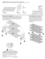
Side rack for shelf, s/s ea., standard, 208/240V SR-2214 SR-2214 SR-2214 SR-2214
Side rack for G/N pans, s/s, option, 230V 14978 14978 14978 14978
Shelf, chrome plated wire, ea., use with SR-2214 SH-2107 SH-2107 SH-2107 SH-2107
Shelf, stainless steel wire, ea., use with SR-2214 or 14978 SH-2326 N/A SH-2326 N/A
Bottom 16253 16253 16253 16253
Casing Back, heavy duty 16260 16260 N/AN/A
Casing Back, standard N/AN/A 16250 16250
Side, heavy duty 16259 16259 N/AN/A
Side, standard N/AN/A 16251 16251
Front Trim 16261 16261 16261 16261
Bonnet 44145 44145 44145 44145
Control Top 44111 44111 44111 44111
Circuit Breaker, 230V ONLY SW-33788 SW-33788 SW-33788 SW-33788
Stacking Hardware, cabinet over cabinet 5001359 5001359 5001359 5001359
Stacking Adapter, carving station over cabinet 16222 16222 16222 16222
Door Assembly, slab, RH or LH (w/gasket) 55649 55649 55649 55649
Door Handle HD-24171 HD-24171 HD-24171 HD-24171
-Mounting Screws for handle (4) SC-2073 SC-2073 SC-2073 SC-2073
-Mounting Screws for latch (2) SC-2070 SC-2070 SC-2070 SC-2070
Door Hinge, ea. HG-2015 HG-2015 HG-2015 HG-2015
Door Gasket, ea. GS-23790 GS-23790 GS-23790 GS-23790
Rubber Bumper Assembly option, full perimeter 44094 44094 44094 44094
-Bumper, Rubber, 8 (2428mm) BM-24766 BM-24766 BM-24766 BM-24766
-Caster, stem, 5" (127mm) swivel w/brake CS-24875 CS-24875 CS-24875 CS-24875
-Caster, stem, 5" (127mm) rigid CS-24874 CS-24874 CS-24874 CS-24874
Insulation IN-2381 IN-2381 IN-2381 IN-2381
Manual Units
Manual Units
Control Face, Manual 16258 16258 16258 16258
Panel Overlay, Manual PE-24659 PE-24659 PE-24659 PE-24659
Thermostat, Manual, 125V, 208/240V, 230V TT-33626 TT-33626 TT-33626 TT-33626
Heat Indicator Light, Manual, 125V LI-3493 LI-3493 LI-3493 LI-3493
Heat Indicator Light, Manual, 208/240V, 230V LI-3923 LI-3923 LI-3923 LI-3923
Temperature Gauge, Manual GU-3273 GU-3273 GU-3273 GU-3273
Thermostat Knob, Manual, Fahrenheit degrees KN-3469 KN-3469 KN-3469 KN-3469
Thermostat Knob, Manual, Celsius degrees KN-3474 KN-3474 KN-3474 KN-3474
Cordset, Manual, 125V, 6 (1829mm) CD-3232 CD-3232 CD-3232 CD-3232
Cordset, Manual, 208/240V, 9 (2743mm) CD-3551 CD-3551 CD-3551 CD-3551
Cordset, Manual, 230V, 9 (2743mm) CD-3922 CD-3922 CD-3922 CD-3922
Electr
Electr
onic Units
onic Units
Control Face 16262 16262 16262 16262
Power Supply Board BA-33554 BA-33554 BA-33554 BA-33554
Electronic Control, Hold ONLY, W/O KITCHEN MGMT 5000872 5000872 5000872 5000872
Electronic Control, Hold ONLY, WITH KITCHEN MGMT 5000873 5000873 5000873 5000873
Electronic Control, Hold W/TIMER, W/O KIT.MGMT. 5000874 5000874 5000874 5000874
Electronic Control, Hold W/TIMER, WITH KIT.MGMT. 5000875 5000875 5000875 5000875
Sensor SN-33541 SN-33541 SN-33541 SN-33541
Terminal block for sensor BK-33546 BK-33546 BK-33546 BK-33546
Relay RL-33558 RL-33558 RL-33558 RL-33558
Reed Switch SW-33559 SW-33559 SW-33559 SW-33559
Terminal Circuit Strip (2) TM-33560 TM-33560 TM-33560 TM-33560
Latch Plate, Electronic PA-24657 PA-24657 PA-24657 PA-24657
Panel Overlay, Electronic PE-24660 PE-24660 PE-24660 PE-24660
Panel Overlay, Electronic Timer PE-24661 PE-24661 PE-24661 PE-24661
Cordset, 125V, 6 (1829mm) CD-3232 CD-3232 CD-3232 CS-3232
Cordset, 208/240V, 9 (2743mm) CD-3551 CD-3551 CD-3551 CD-3551
Cordset, 230V, 9 (2743mm) CD-3922 CD-3922 CD-3922 CD-3922
Beeper BP-3567 BP-3567 BP-3567 BP-3567
500-S/HD 500-S/HD/PT 500-S/STD 500-S/STD/PT
#823/32/36 INSTALLATION/OPERATION/SERVICE MANUAL 18.
#823/32/36 INSTALLATION/OPERATION/SERVICE MANUAL 19.
Service Parts
Description Part Numbers
Manual
Manual
or
or
Electr
Electr
onic Units
onic Units
Side rack for shelf, s/s ea., standard, 208/240V SR-2219 SR-2219 SR-2219 SR-2219
Side rack for G/N pans, s/s, option, 230V 14979 14979 14979 14979
Shelf, chrome, wire, ea., use with SR-2219 SH-2105 SH-2327 SH-2105 SH-2327
Shelf, stainless steel wire, ea., use with SR-2214 or 14978 SH-2324 N/A SH-2324 N/A
Bottom 44099 44099 44099 44099
Casing Back, heavy duty 16228 N/AN/AN/A
Casing Back, standard N/AN/A 16225 N/A
Side, heavy duty 16229 16229 N/AN/A
Side, standard N/AN/A 16224 16224
Front Trim 16235 16235 16235 16235
Bonnet 16232 16232 16232 16232
Control Top 44097 44097 44097 44097
Circuit Breaker, 230V ONLY SW-33788 SW-33788 SW-33788 SW-33788
Stacking Hardware, cabinet over cabinet 5001359 5001359 5001359 5001359
Stacking Adapter, carving station over cabinet 16237 16237 16237 16237
Door Assembly, slab, RH or LH (w/gasket) 55648 55648 55648 55648
Door Handle HD-24171 HD-24171 HD-24171 HD-24171
-Mounting Screws for handle (4) SC-2073 SC-2073 SC-2073 SC-2073
-Mounting Screws for latch (2) SC-2070 SC-2070 SC-2070 SC-2070
Door Hinge, ea. HG-2015 HG-2015 HG-2015 HG-2015
Door Gasket, ea. GS-23778 GS-23778 GS-23778 GS-23778
Rubber Bumper Assembly option, full perimeter 44107 44107 44107 44107
-Bumper, Rubber, 10 (3048mm) BM-24766 BM-24766 BM-24766 BM-24766
-Caster, stem, 5" (127mm) swivel w/brake CS-24875 CS-24875 CS-24875 CS-24875
-Caster, stem, 5" (127mm) rigid CS-24874 CS-24874 CS-24874 CS-24874
Insulation IN-2381 IN-2381 IN-2381 IN-2381
Manual Units
Manual Units
Control Face 16234 16234 16234 16234
Panel Overlay, Manual PE-24662 PE-24662 PE-24662 PE-24662
Thermostat, Manual, 125V, 208/240V, 230V TT-33626 TT-33626 TT-33626 TT-33626
Heat Indicator Light, Manual, 125V LI-3493 LI-3493 LI-3493 LI-3493
Heat Indicator Light, Manual, 208/240V, 230V LI-3923 LI-3923 LI-3923 LI-3923
Temperature Gauge, Manual GU-3273 GU-3273 GU-3273 GU-3273
Thermostat Knob, Manual, Fahrenheit degrees KN-3469 KN-3469 KN-3469 KN-3469
Thermostat Knob, Manual, Celsius degrees KN-3474 KN-3474 KN-3474 KN-3474
Cordset, Manual, 125V, 6 (1829mm) CD-3232 CD-3232 CD-3232 CD-3232
Cordset, Manual, 208/240V, 9 (2743mm) CD-3551 CD-3551 CD-3551 CD-3551
Cordset, Manual, 230V, 9 (2743mm) CD-3922 CD-3922 CD-3922 CD-3922
Electr
Electr
onic Units
onic Units
Control Face 16230 16230 16230 16230
Power Supply Board BA-33554 BA-33554 BA-33554 BA-33554
Electronic Control, Hold ONLY, W/O KITCHEN MGMT 5000872 5000872 5000872 5000872
Electronic Control, Hold ONLY, WITH KITCHEN MGMT 5000873 5000873 5000873 5000873
Electronic Control, Hold W/TIMER, W/O KIT.MGMT. 5000874 5000874 5000874 5000874
Electronic Control, Hold W/TIMER, WITH KIT.MGMT. 5000875 5000875 5000875 5000875
Sensor SN-33541 SN-33541 SN-33541 SN-33541
Terminal block for sensor BK-33546 BK-33546 BK-33546 BK-33546
Relay RL-33558 RL-33558 RL-33558 RL-33558
Reed Switch SW-33559 SW-33559 SW-33559 SW-33559
Terminal Circuit Strip (2) TM-33560 TM-33560 TM-33560 TM-33560
Latch Plate, Electronic PA-24657 PA-24657 PA-24657 PA-24657
Panel Overlay, Electronic PE-24663 PE-24663 PE-24663 PE-24663
Panel Overlay, Electronic Timer PE-24664 PE-24664 PE-24664 PE-24664
Cordset, 125V, 6 (1829mm) CD-3232 CD-3232 CD-3232 CD-3232
Cordset, 208/240V, 9 (2743mm) CD-3551 CD-3551 CD-3551 CD-3551
Cordset, 230V, 9 (2743mm) CD-3922 CD-3922 CD-3922 CD-3922
Beeper BP-3567 BP-3567 BP-3567 BP-3567
750-S/HD 750-S/HD/PT 750-S/STD 750-S/STD/PT
  • Page 1 1
  • Page 2 2
  • Page 3 3
  • Page 4 4
  • Page 5 5
  • Page 6 6
  • Page 7 7
  • Page 8 8
  • Page 9 9
  • Page 10 10
  • Page 11 11
  • Page 12 12
  • Page 13 13
  • Page 14 14
  • Page 15 15
  • Page 16 16
  • Page 17 17
  • Page 18 18
  • Page 19 19
  • Page 20 20
  • Page 21 21
  • Page 22 22
  • Page 23 23
  • Page 24 24
  • Page 25 25
  • Page 26 26
  • Page 27 27
  • Page 28 28
  • Page 29 29
  • Page 30 30
  • Page 31 31
  • Page 32 32
  • Page 33 33
  • Page 34 34
  • Page 35 35
  • Page 36 36
  • Page 37 37
  • Page 38 38
  • Page 39 39
  • Page 40 40
  • Page 41 41
  • Page 42 42
  • Page 43 43

Alto-Shaam 1000-S Series Installation, Operation and Maintenance Manual

Category
Thermostats
Type
Installation, Operation and Maintenance Manual
This manual is also suitable for

Ask a question and I''ll find the answer in the document

Finding information in a document is now easier with AI