PG. 12 #825/33/37 INSTALLATION/OPERATION/SERVICE MANUAL
1. TOP ASSEMBLY 1 4174
2. TOP ASSEMBLY MOUNTING SCREWS 5 SC-2425
3. TUBE TOP MOUNTING SCREWS 2 SC-2332
4. TUBE BOTTOM MOUNTING SCREWS 2 SC-2425
BOTTOM FILLER (not shown) 1 1002
CAPILLARY GUARD MOUNTING SCREWS (not shown) 4 SC-2425
CAPILLARY GUARD (not shown) 2 GD-2450
CAPILLARY BULB MOUNTING SCREWS (not shown) 4 SC-2077
CAPILLARY BULB HOLD-DOWN (not shown) 4 BK-2609
THERMOSTAT CAPILLARY BULB (not shown) 2 —
5. HOLD THERMOSTAT KNOB (Fahrenheit) 1 KN-3469
HOLD THERMOSTAT KNOB (Celsius) 1 KN-3474
6. COOK THERMOSTAT KNOB (Fahrenheit) 1 KN-3468
COOK THERMOSTAT KNOB (Celsius) 1 KN-3475
7. TIMER KNOB 1 —
TIMER NUT (not shown) 1 —
8. SWITCH NUT 1 NU-2355
9. CONTROL PANEL MOUNTING SCREWS 1 SC-2459
CONTROL PANEL MOUNTING SCREWS 5 SC-2425
10. CONTROL PANEL 1 4537
11. CABLE COVER PLATE MOUNTING SCREWS 4 SC-2459
12. CABLE COVER PLATE 2 1324
13. TUBE ASSEMBLY 1 —
14. CASING ASSEMBLY 1 4601
15. INSULATION TUBE MOUNTING SCREWS 6 SC-2459
16. INSULATION TUBE (Left-hand) 1 4170
17. INSULATION TUBE (Right-hand) 1 1163
18. INSULATION: 25" x 120" (635mm x 3048mm) 1 IN-22364
19. CABLE CONNECTION HARDWARE
20. HEATING CABLE: 125V, Length 95' (38956mm) 1 CB-3045
HEATING CABLE: 208-240V, Length 189' (57607mm) 1 CB-3045
21. DOOR ASSEMBLY, RIGHT-HAND (Slab) 1 5178
DOOR ASSEMBLY, LEFT-HAND (Slab) 1 15538
DOOR ASSEMBLY, RIGHT-HAND (Window) 1 5452
DOOR ASSEMBLY, LEFT-HAND (Window) 1 5471
22. HINGE SET (1 pair of 2 hinges) 1 HG-2014
HINGE TO DOOR MOUNTING SCREWS (not shown) 6 SC-2072
HINGE TO UNIT MOUNTING SCREWS (not shown) 6 SC-2073
23. DOOR HANDLE 1 HD-2566
DOOR HANDLE MOUNTING SCREWS (not shown) 4 SC-2073
DOOR CATCH MOUNTING SCREWS (not shown) 2 SC-2162
24.DOOR GASKET: Length 9' (2743mm) 1 GS-2398
25. SIDE RACK 2 SR-2303
SIDE RACK FOR PAN SLIDE, 230V ONLY 2 14979
26. SHELF 3 SH-2324
27. DRIP PAN 1 14831
28. HOLD THERMOSTAT 1 TT-3057
29. COOK THERMOSTAT 1 TT-3329
30. CABLE AND POWER INDICATOR LIGHTS
—125V 3 LI-3027
—Red, 208-240V, 60 Hz 3 LI-3025
—White, 230V, 50 Hz 3 LI-3951
31. TIMER: 125V 1 TR-3504
TIMER: 208V, 240V—60 Hz 1 TR-3318
TIMER: 230V—50Hz 1 TR-3402
32. POWER SWITCH: 125V, 208-240V, 60 Hz 1 SW-3528
POWER SWITCH: 230V, 50 Hz 1 SW-3950
33. CONTACTOR: 125V 1 CN-3487
CONTACTOR: 208-240V-60 Hz, 230V-50 Hz (TUV) 1 CN-3052
34. FAN: 125V 2 FA-3485
FAN: 208-240V 2 FA-3342
FAN BLADE 2 FA-3343
35. VOLTAGE CONVERSION SWITCH 1 SW-3528
36. CORD: 125V 1 CD-3397
CORDSET: 230V (Type HO7 RN-F) 1 CD-3922
37. DRIP TRAY HOLDER 1 11259
38. DRIP TRAY HOLDER MOUNTING SCREWS 3 SC-2425
39. DRIP TRAY 1 11258
40. FILTER, LINE, 230V ONLY 1 FI-33225
41. HOLDER, THERMOSTAT (not shown) 1 13958
HOLDER MTG. SCREWS 2 SC-2459
THERMOSTAT, HI LIMIT, RESET, 230V ONLY 1 TT-33476
42. BELL TIMER/KNOB FOR DELUXE MODELS ONLY (not shown) 1 TR-22388
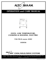
SERVICE VIEW PARTS LIST
750-TH-II
DISCONNECT OVEN FROM POWER
SOURCE BEFORE SERVICING
5/1/01 PART DESCRIPTION UNIT ALTO-SHAAM
QUANTITY PART NUMBER
PART DESCRIPTION UNIT ALTO-SHAAM
QUANTITY PART NUMBER
Cable Heating Service Kit #4881 #4879
208-240V 125V
includes:
CB-3045 Cable Heating Element 210 feet 112 feet
CR-3226 Ring Connector 12 6
IN-3488 Insulation Corner 1 foot 1 foot
BU-3105 Shoulder Bushing 12 6
BU-3106 Cup Bushing 12 6
SL-3063 Insulating Sleeve 12 6
TA-3540 Electrical Tape 1 roll 1 roll
ST-2439 Stud 10-32 12 6
NU-2215 Hex Nut 10-32 24 12