Page is loading ...

-1-
VHD+ Pre Amplier Module
for 500 Series Racks
User Guide

-2-
Safety and Installation Considerations
This page contains denitions, warnings, and practical information to ensure a safe
working environment. Please take time to read this page before installing or using this
apparatus.
General Safety
• Read these instructions.
• Keep these instructions.
• Heed all warnings.
• Follow all instructions.
• Do not use this apparatus near water.
• Do not expose this apparatus to rain or moisture.
• Clean only with dry cloth.
• Do not block any ventilation openings.
• Install in accordance with the rack manufacturer’s instructions.
• There are no user-adjustments, or user-servicable items, on this apparatus.
• Adjustments or alterations to this apparatus may affect the performance such
that safety and/or international compliance standards may no longer be met.
• This apparatus is not to be used in safety critical applications
Caution
• This apparatus should not be used outside of the scope of API 500 series
compatible racks.
• Do not operate this apparatus with any covers removed.
• To reduce the risk of electric shock, do not perform any servicing other than that
contained in these Installation Instructions unless you are qualied to do so. Refer
all servicing to qualied service personnel.
Installation
• Ensure power is removed from the rack before tting or removing this apparatus to
or from the rack.
• Use the panel xing screws supplied with the rack to secure this apparatus into the
rack.

-3-
Standards Compliance
This apparatus is designed to be installed and used in API
500 series compatible racks which are CE marked. The CE
mark on a rack is indicative that the manufacturer conrms
that it meets both EMC and the Low Voltage Directive
(2006/95/EC).
Instructions for Disposal of WEEE by Users in the
European Union
The symbol shown here is on the product or on its
packaging, which indicates that this product must not
be disposed of with other waste. Instead, it is the user’s
responsibility to dispose of their waste equipment by
handing it over to a designated collection point for recycling of
waste electrical and electronic equipment. The separate collection
and recycling of your waste equipment at the time of disposal will
help to conserve natural resources and ensure that it is recycled
in a manner that protects human health and the environment.
For more information about where you can drop off your waste
equipment for recycling, please contact your local city ofce, your
household waste disposal service or where you purchased the
product.
Limited Warranty
Please refer any warranty claim to the supplier of this equipment in
the rst instance. Full warranty information for equipment supplied
directly by Solid State Logic can be found on our website:
www.solidstatelogic.com

-4-
Introduction
Congratulations on your purchase of this API 500 format compatible
SSL VHD+™ Pre Module.
This module has been specically designed to operate in a 500 for-
mat rack such as the API lunchbox® or equivalent. In common with
many such modules, the nominal input/output level is +4 dBu.
The VHD+ Pre is an immensely versatile recording and processing
device. It can deliver ultra clean SSL SuperAnalogue™ grade re-
cordings but also features a switchable VHD mode. SSL’s patented
Variable Harmonic Drive (VHD) system uses a 100% analogue sig-
nal path to generate rich harmonic distortion. As you increase VHD
input gain, the Variable Harmonic Drive process introduces either
2nd or 3rd harmonic distortion or a blend of the two to your source
material. At lower gain settings it adds gentle valve-style warmth
or a touch of transistor edge. As the gain is increased the more
extreme the distortion becomes until at high gain settings it delivers
erce trashy transistoresque grunge.
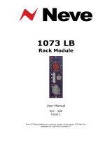
Operation
Please refer to the illustration opposite.
Signal LED
The signal LED is a tri-colour LED that indicates level according to
the following table.
LED colour +24dB Scale* +18dB Scale*
Green -24dBu -24dBu
Yellow +4dBu 0dBu
Red +21 dBu +16dBu
* The LED scale is selected from a jumper on the module PCB.
1

-5-
1
2
3
4
Gain Controls
The red pot provides up to +75 dB of gain,
whilst the black pot provides a variable
mix of 2nd to 3rd order harmonics (once
the VHD-IN switch is engaged).
The grey pot provides +/- 20dB of trim.
Use this to control the output when driving
the VHD preamplier circuit.
High Pass Filter
The High Pass Filter section is a
switchable 18dB/Octave variable lter.
See the block diagram for the position in
the circuit.
Line In/DI Jack Socket
The front panel 1/4” Tip/Ring/Sleeve
(TRS) Jack Socket provides a convenient
way to connect instruments when the
module is tted in a rack.
5
2
3
6
4
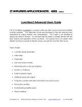
This balanced input overrides the rear XLR and has a 10KΩ input
impedance and features a -10dB level pad to allow for typically
louder balanced line level signals. The Jack input can also be used
with unbalanced (TS) cables. The input level and impedance are
switched to 0dB and 1MΩ respectively (for very high impedance
sources such as guitar pick-ups) with selection of the HI-Z switch.
Input Impedances
The rear XLR and front Jack inputs have different impedances
available by using the Hi-Z switch and allow for a wide variety of
sources. The XLR input impedance changes from 1.2 KΩ to 10KΩ
and the front panel Jack changes from 10KΩ to 1MΩ.
5

-6-
Ø
FRONT
JACK
10K
FRONT
TRS
JACK
1.2K
1M
+48V
48V
REAR
XLRF
HI-Z
HPF IN
15-500Hz
HPF
TRIM
+dB
-20 to +20dB
REAR
XLRM
GAIN
+dB
+20 to +75dB
-20dB
PAD
SIGNAL
10K
-10dB
Block Diagram

-7-
Using the preamplier
When the VHD button is not engaged, the preamplier has been
designed to give a transparent sound, great for sources such as
acoustic guitars, vocals and strings.
When the VHD button is pressed, the preamplier can be driven to
give a wide-range of overdriven sounds, ranging from subtle to...
well, not so subtle! Drums and electronic instruments can often
benet from VHD colouration.
The best way to drive the VHD preamplier is to increase the input
gain (red pot) whilst using the Line Trim pot to reduce the overall
level and not clip the channel output. Remember, it’s the input to
the preamplier that likes being driven. From this point, adjust the
harmonics to ne-tune the desired sound.
48v
PAD
HI-Z
Ø
Applies phantom power to the rear XLR input, a tell tale red
LED indicates phantom power is active.
Applies 20 dB of attenuation before the signal enters the
preamplier.
Switches the XLR Mic preamplier impedance from 1.2 KΩ
to 10KΩ or the front panel Jack from 10KΩ to 1MΩ
Polarity switch inverts the polarity of the signal by 180°.
Switch Functions
6

-8-
Visit SSL at:
www.solidstatelogic.com
© Solid State Logic
All rights reserved under International and Pan-American Copyright Conventions
SSL® and Solid State Logic® are ® registered trademarks of Solid State Logic.
SuperAnalogue™ and VHD+™ are trademarks of Solid State Logic.
All other product names and trademarks are the property of their respective owners and
are hereby acknowledged.
No part of this publication may be reproduced in any form or by any means, whether
mechanical or electronic, without the written permission of Solid State Logic, Oxford, OX5
1RU, England.
As research and development is a continual process, Solid State Logic reserves the right
to change the features and specications described herein without notice or obligation.
Solid State Logic cannot be held responsible for any loss or damage arising directly or
indirectly from any error or omission in this manual.
PLEASE READ ALL INSTRUCTIONS, PAY SPECIAL HEED TO SAFETY WARNINGS.
E&OE
July 2020
Revision History
Revision V2.0, June 2020 - Revised Layout Release for Module Update
/