Supermicro P4DP6 Reference guide

Type
Reference guide

Supermicro P4DP6 offers exceptional performance and versatility for various applications. With its dual Xeon processor support, registered ECC memory, and ample expansion slots, it excels in multitasking, data-intensive computing, and server environments. The integrated Adaptec 7899W SCSI chip and Ultra SCSI ports enable fast data transfer speeds for storage-demanding applications. Additionally, the IPMI port allows for remote management and monitoring, enhancing system uptime and accessibility.

Supermicro P4DP6 offers exceptional performance and versatility for various applications. With its dual Xeon processor support, registered ECC memory, and ample expansion slots, it excels in multitasking, data-intensive computing, and server environments. The integrated Adaptec 7899W SCSI chip and Ultra SCSI ports enable fast data transfer speeds for storage-demanding applications. Additionally, the IPMI port allows for remote management and monitoring, enhancing system uptime and accessibility.

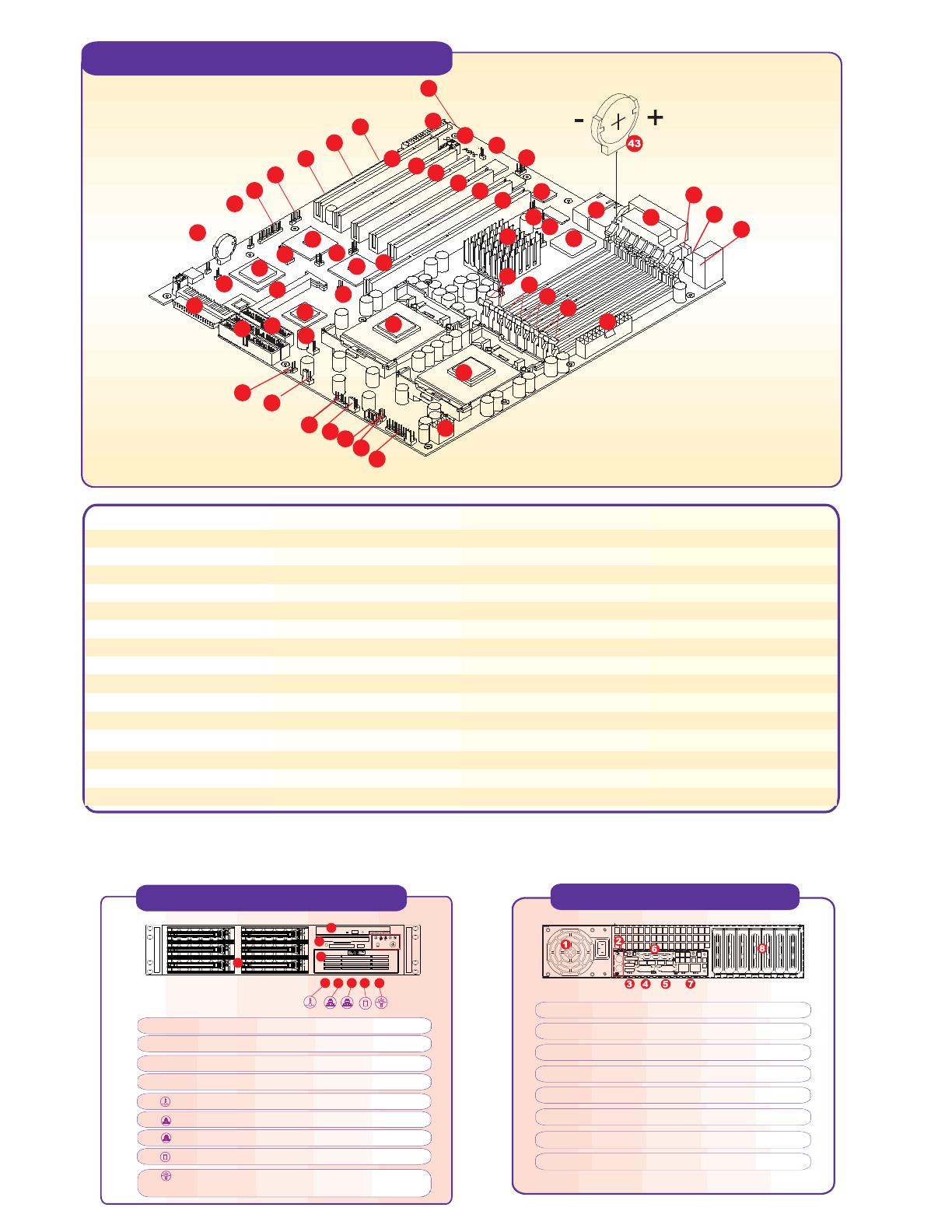
Motherboard Components
Note: Interleaved ECC registered memory requires DDR DIMMs to be installed in pair.
*
1 Super P4DP6 motherboard
2 JA4: Ultra SCSI CH B
3 JBT1: CMOS clear
4 JWOR: wake-on-ring Header
5 WOL: wake-on-LAN header
6,7,8,9,10 JP10-JP21: PCI-X bus speed setting
11 USB2, USB3
12 JP32: ACPI/sleep button header
13 JD1: PWR LED/speaker/NMI header
14 JPA1: SCSI termination
15 JA1: Ultra III LVD SCSI CH A
16 J2A/J3A: IDE#1/IDE#2 drive conn.
17 JP7: floppy drive conn.
18 IPMI port
19 Adaptec 7899W SCSI chip
20 ICH3
21,22 P64H2
23 CPU2 fan
24 JL1: chassis intrusion header
25 CPU2/chassis fan
26 USB 4
27 JP33: CPU1/chassis fan
28 JP9: third power fail header
29 JP36: alarm reset switch
30 JF2: front control panel conn.
31 Secondary ATX power conn.
32, 33 CPU1, CPU2
34, 35, 36, 37 Bank1, 2, 3, 4
38 ATX power conn.
39 Keyboard & mouse
40 USB 0 & USB1
41, 42 COM1, VGA, parallel port
43 Battery
44 LAN1, LAN2 ports
45 ATI rage XL graphic chip
46 Overheat fan
47 MCH
48 JP4: VGA enable/disbale
49 JP38: thermal fan enable/disbale
50 JP3 /JP27: LAN1/LAN2 enable/disable
51 JP17/Bus 1B (PCI-X 133MHz, slot #6)
52 JP18/Bus 1A (PCI-X 133MHz, slot #5)
53 JP19/Bus 2A (PCI-X 100MHz, slot #4)
54 JP20/Bus 2B (PCI-X 66MHz, slot #3)
55 JP21/Bus 2B (PCI-X 66MHz, slot #2)
56 JP23/Bus 2B (PCI-X 66MHz, slot #1)
57 JP35: keylock switch conn.
58 COM2
33
31
29
34
11
12
30
5
4
2
3
28
27
26
25
23
1
15
14
13
35
19
18
10
32
7
6
8
9
24
22
21
20
16
36
37
38
17
39
40
41
42
44
45
46
47
48
49
50
51
52
53
54
55
56
57
58
Rear Panel Functions
1. AC power connector
2. PS/2 mouse and keyboard ports
3. 2 USB ports
4. COM 1 port
5. VGA port
6. Parallel port
7. 2 x Intel 82550 LAN ports
8. 7 I/O expansion slots
Front Panel Functions
5
6
7
8
1
2
4
3
9
1. 6 SCA Ultra160 hot-swap drive bays
2. 1 slim CD-ROM drive
3. Floppy Drive
4. 1 x 5.25" drive bay
5. Overheat: Indicates an overheat condition in the system
6. NIC2: Indicates network activity on LAN2 when flashing
7 NIC1: Indicates network activity on LAN1 when flashing
8. HDD: Indicates IDE channel activity
9. Power: Indicates power is being supplied to the system's
power supply units
To protect the system and components, it is essential that you reinstall the top panel after you have finished working on the system.
P4DP6 Quick Reference
Jumpers Description Default Setting
JPA1  LVD SCSI Ch A term. Open (Enabled)
JPA2  LVD SCSI Ch B term. Open (Enabled)
JBT1  CMOS clear  Pins 1-2 (Normal)
JP9 Power fail alarm en/disable Open (Disabled)
JD1 Speaker enable/disable Closed 6-7 (Enabled)
JP3  LAN1 enable/disable Pins 1-2 (Enabled)
JP27  LAN2 enable/disable Pins 1-2 (Enabled)
JP22 SCSI enable/disable Pins 1-2 (Enabled)
JP38 Thermal fan enable/disable Open (BIOS control)
JP4  VGA enable/disable Pins 1-2 (Enabled)
JP33 CPU chassis/CPU fan select Close (CPU Fan)
Warning !
CPU Heatsink Installation Procedure
(For Supermicro SuperServer 2U Systems)
Due to the fact that adequate air flow and proper thermal control are very critical in maintaining 1U
system's stability and performance, it is imperative that the proper installation procedures listed
below be followed in order to maximize system performance. This is especially critical for 2U dual
Xeon processor server solutions.
1) Only those CPU heatsinks that are provided by Supermicro should be used.
2) Apply a small amount of silicon compound on the CPU's die.
3) Place the CPU heatsink on top of the CPU.
4) Attach the heatsink clips to the heatsink retention pieces, one on each
side of the heatsink as shown in the diagram at right.
5) The three tabs on each heatsink retention pieces should completely
protrude though the corresponding holes on the heatsink clips.
  • Page 1 1
  • Page 2 2

Supermicro P4DP6 Reference guide

Type
Reference guide

Supermicro P4DP6 offers exceptional performance and versatility for various applications. With its dual Xeon processor support, registered ECC memory, and ample expansion slots, it excels in multitasking, data-intensive computing, and server environments. The integrated Adaptec 7899W SCSI chip and Ultra SCSI ports enable fast data transfer speeds for storage-demanding applications. Additionally, the IPMI port allows for remote management and monitoring, enhancing system uptime and accessibility.

Ask a question and I''ll find the answer in the document

Finding information in a document is now easier with AI