Page is loading ...

LBC-4000
L-Band Up/Down Converter System
Installation and Operation Manual
Part Number MN/LBC4000.IOM
Revision 2


Filename: T_ERRATA 1
Errata A
Comtech EF Data Documentation Update
Subject:
Appendix A. Remote Control Operation
Date:
June 13, 2006
Document:
LBC-4000 L-Band Up/Down Converter System Installation and
Operation Manual, Rev. 2 dated March 30, 2006
Part Number:
MN/LBC4000.EA2
Collating Instructions:
Attach this page to page A-15
Comments:
Change CMS Commands to eliminate the comma delimited sentence as follows:
Change Specifics:

Filename: T_ERRATA 2
Parameter
Type
Command
(Instruction
Code and
qualifier)
Arguments for
Command or
Response to
Query
Description of arguments
(Note that all arguments are ASCII numeric codes, that
is, ASCII codes between 48 and 57)
Response to
Command
(target to
controller)
Query
(Instruction
Code and
qualifier)
Response to
Query
(target to
controller)
Concise
Maintenance
Status
N/A 70 bytes
numerical
Query only.
Used to Query the Maintenance status of the unit in concise
format.
Syntax:
CMS_aaa.abbb.bccc.cddd.deee.efff.fggg.ghhh.hiii.ijjj.jkkk.klll
.lmmm.mnnn.nooo.oppp.pqqq.q’cr’’lf’
where:
aaa.a =12 VDC supply #1 in volts
bbb.b = 8 VDC supply #1 in volts
ccc.c = 5 VDC supply #1 in volts
ddd.d = 12 VDC supply #2 in volts
eee.e = 8 VDC supply #2 in volts
fff.f= 5 VDC supply #2 in volts
ggg.g = Ref Osc tuning voltage in volts
hhh.h = Converter A IFLO tuning voltage in volts
iii.i= Converter A RFLO tuning voltage involts
jjj.j = Converter A Input Power in dBm
(Reserved for future use)
kkk.k = Converter A Output Power in dBm
(Reserved for Future use)
lll.l= Converter A temperature in degrees C
mmm.m = Converter B IFLO tuning voltage in volts
nnn.n= Converter B RFLO tuning voltage in volts
ooo.o = Converter B Input Power in dBm
(Reserved for future use)
ppp.p =Converter B Output Power in dBm
(Reserved for future use)
qqq.q = Converter B temperature in degrees C
N/A CMS_
CMS_
x….x
(see description for
details of
arguments)

Filename: T_ERRATA 1
Errata B
Comtech EF Data Documentation Update
Subject:
Add figure for redundant operation.
Date:
September 7, 2006
Document:
LBC-4000 L-Band Up/Down Converter System Installation and
Operation Manual, Rev. 2 dated March 30, 2006
Part Number:
MN/LBC4000.EB2
Collating Instructions:
Attach this page to page 2-3
Comments:
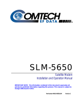
Add figure representing cabling requirements for redundant operation.
Change Specifics:

Filename: T_ERRATA 2
To Modem
To Block Converter
Termination Termination
SLOT
B
SLOT
A
The drawing represents the cabling requirements for redundant operation. BNC to BNC cables should
be 50 Ω BNC-M. Type N to SMA connections is best made with a Type N-M to SMA-F adapter and
SMA-SMA cables.

Copyright © Comtech EF Data, 2001. All rights reserved. Printed in the USA.
Comtech EF Data, 2114 West 7th Street, Tempe, Arizona 85281 USA, (480) 333-2200, FAX: (480) 333-2161.
LBC-4000
L-Band Up/Down Converter System
Installation and Operation Manual
Part Number MN/LBC4000.IOM
Revision 2
March 30, 2006
Comtech EF Data is an ISO 9001
Registered Company

LBC-4000 L-Band Up/Down Converter System MN/LBC4000.IOM
Preface Revision 2
ii
CUSTOMER SUPPORT
Contact the Comtech EF Data Customer Support Department for:
Product support or training
Information on upgrading or returning a product
Reporting comments or suggestions concerning manuals
A Customer Support representative may be reached at:
Comtech EF Data
Attention: Customer Support Department
2114 West 7th Street
Tempe, Arizona 85281 USA
480.333.2200 (Main Comtech EF Data Number)
480.333.4357 (Customer Support Desk)
480.333.2161 FAX
or, E-Mail can be sent to the Customer Support Department at:
Contact us via the web at www.comtechefdata.com
.
To return a Comtech EF Data product (in-warranty and out-of-warranty) for repair or replacement:
1. Request a Return Material Authorization (RMA) number from the Comtech EF
Data Customer Support Department.
2. Be prepared to supply the Customer Support representative with the model
number, serial number, and a description of the problem.
3. To ensure that the product is not damaged during shipping, pack the product in
its original shipping carton/packaging.
4. Ship the product back to Comtech EF Data. (Shipping charges should be
prepaid.)
For more information regarding the warranty policies, see Warranty Policy, p. viii.

iii
Table of Contents
CHAPTER 1. INTRODUCTION ............................................................................................1-1
1.1 Overview .............................................................................................................................................1-1
1.2 Functional Description ......................................................................................................................1-1
1.3 Specifications ......................................................................................................................................1-3
1.4 Front Panel Display ...........................................................................................................................1-5
CHAPTER 2. INSTALLATION .............................................................................................2-1
2.1 Unpacking and Inspection.................................................................................................................2-1
2.2 Rack Mount Installation....................................................................................................................2-1
2.3 Module Installation/Removal............................................................................................................2-2
2.4 Prime Power Connection...................................................................................................................2-3
2.5 Cable Connections .............................................................................................................................2-3
2.5.1 Rear Panel Connections................................................................................................................2-3
2.5.2 RS-485/RS-232C Interface (COM 1), Connector J1....................................................................2-4
2.5.3 Summary Fault Output (RELAY) and Serial Port........................................................................2-5
CHAPTER 3. SYSTEM OPERATION ..................................................................................3-1
3.1 Overview .............................................................................................................................................3-1
3.2 Switching Power ON .........................................................................................................................3-3
3.3 Operation............................................................................................................................................3-3
3.3.1 Converter Commands ...................................................................................................................3-7
3.3.2 Configuration Functions Menu.....................................................................................................3-8
3.3.3 Utility Function Menu ................................................................................................................3-13

L-Band Up/Down Converter System MN/LBC4000.IOM
Preface Revision 2
iv
APPENDIX A. REMOTE CONTROL................................................................................... A-1
A.1 General..............................................................................................................................................A-1
A.1.1 RS-485 ........................................................................................................................................A-1
A.1.2 RS-232 ........................................................................................................................................A-2
A.2 Basic Protocol ...................................................................................................................................A-2
A.3 Packet Structure...............................................................................................................................A-3
A.3.1 Start of Packet.............................................................................................................................A-3
A.3.2 Address .......................................................................................................................................A-3
A.3.3 Instruction Code..........................................................................................................................A-4
A.3.4 Instruction Code Qualifier ..........................................................................................................A-4
A.3.5 Error Response............................................................................................................................A-5
A.3.6 Message Arguments....................................................................................................................A-5
A.3.7 End of Packet..............................................................................................................................A-5
A.4 Remote Commands ..........................................................................................................................A-6
Figures
Figure 1-1. LBC-4000 L-Band Up/Down Converter System ....................................................................1-1
Figure 1-2. LBC-4000 Typical Application...............................................................................................1-2
Figure 1-3. LBC-4000 Dimensional Envelope ..........................................................................................1-5
Figure 3-1. LBC-4000 ...............................................................................................................................3-1
Figure 3-2. Keypad ....................................................................................................................................3-4
Tables
Table 1-1. Specifications ...........................................................................................................................1-3
Table 2-1. Rear Panel Connectors..............................................................................................................2-1
Table 2-2. J1, 2 Wire RS-485 Interface Pin-Out.......................................................................................2-2
Table 2-3. J1, 4 Wire RS-485 Interface Pin-Out.......................................................................................2-2
Table 2-4. J1, RS-232C Interface Pin-Out...............................................................................................2-2
Table 2-5. P1, Summary Fault Connector Pin-Out...................................................................................2-5
Table 2-6. Serial Port (J1) DB-9F..............................................................................................................2-3
Table 3-1. Operating Functions – Front Panel..........................................................................................3-2
Table 3-2. LBC-4000 Command Function Menus ....................................................................................3-5
Table A-1. Customer Commands..............................................................................................................A-7

L-Band Up/Down Converter System MN/LBC4000.IOM
Preface Revision 2
v
ABOUT THIS MANUAL
This manual provides installation and operation information for the Comtech EF Data LBC-4000,
L-Band Up/Down Converter System. This is a technical document intended for earth station
engineers, technicians, and operators responsible for the operation and maintenance of the LBC-
4000, L-Band Up/Down Converter System.
CONVENTIONS AND REFERENCES
CAUTIONS AND WARNINGS
IMPORTANT
Indicates information critical for proper equipment function.
CAUTION
Indicates a hazardous situation that, if not avoided, may result in minor or
moderate injury. CAUTION may also be used to indicate other unsafe practices
or risks of property damage.
WARNING
Indicates a potentially hazardous situation that, if not avoided, could result in
death or serious injury.
METRIC CONVERSION
Metric conversion information is located on the inside back cover of this manual. This
information is provided to assist the operator in cross-referencing non-Metric to Metric
conversions.
TRADEMARKS
All product names mentioned in this manual may be trademarks or registered trademarks of their
respective companies and are hereby acknowledged.
RECOMMENDED STANDARD DESIGNATIONS
Recommended Standard (RS) Designations have been superseded by the new designation of the
Electronic Industries Association (EIA). References to the old designations are shown only when
depicting actual test displayed on the screen of the unit (RS-232, RS-485, etc.). All other
references in the manual will be shown with the EIA designations.
REPORTING COMMENTS OR SUGGESTIONS CONCERNING THIS MANUAL
Comments and suggestions regarding the content and design of this manual will be appreciated.
To submit comments, please contact the Comtech EF Data Customer Support Department.

L-Band Up/Down Converter System MN/LBC4000.IOM
Preface Revision 2
vi
EMC COMPLIANCE
This is a Class A product. In a domestic environment, it may cause radio interference that requires the
user to take adequate protection measures.
EN55022 COMPLIANCE
This equipment meets the radio disturbance characteristic specifications for information
technology equipment as defined in EN55022.
EN50082-1 COMPLIANCE
This equipment meets the electromagnetic compatibility/generic immunity standard as defined in
EN50082-1.
FEDERAL COMMUNICATIONS COMMISSION (FCC)
This equipment has been tested and found to comply with the limits for a Class A digital device,
pursuant to Part 15 of the FCC rules. These limits are designed to provide reasonable protection
against harmful interference when the equipment is operated in a commercial environment.
This equipment generates, uses, and can radiate radio frequency energy. If not installed and used
in accordance with the instruction manual, it may cause harmful interference to radio
communications. Operation of this equipment in a residential area is likely to cause harmful
interference; in which case, users are required to correct the interference at their own expense.
Note: To ensure compliance, properly shielded cables for DATA I/O shall be used. More
specifically, these cables shall be shielded from end to end, ensuring a continuous shield.
C
HANGES MADE TO REV. 1
Incorporated Errata’s A and B
Incorporated all engineering comments.

L-Band Up/Down Converter System MN/LBC4000.IOM
Preface Revision 2
vii
SAFETY COMPLIANCE
EN 60950
Applicable testing is routinely performed as a condition of manufacturing on all units to ensure
compliance with safety requirements of EN60950.
This equipment meets the Safety of Information Technology Equipment specification as defined
in EN60950.
LOW VOLTAGE DIRECTIVE (LVD)
The following information is applicable for the European Low Voltage Directive (EN60950):
<HAR> Type of power cord required for use in the European Community.
!
CAUTION: Double-pole/Neutral Fusing.
ACHTUNG: Zweipolige bzw. Neutralleiter-Sicherung.
International Symbols:
Symbol Definition Symbol Definition
Alternating Current.
Protective Earth.
Fuse.
Chassis Ground.
Note: For additional symbols, refer to “Cautions” listed earlier in this preface.

L-Band Up/Down Converter System MN/LBC4000.IOM
Preface Revision 2
viii
WARRANTY POLICY
This Comtech EF Data product is warranted against defects in material and workmanship for a
period of two years from the date of shipment. During the warranty period, Comtech EF Data
will, at its option, repair or replace products that prove to be defective.
For equipment under warranty, the customer is responsible for freight to Comtech EF Data and all
related custom, taxes, tariffs, insurance, etc. Comtech EF Data is responsible for the freight
charges only for return of the equipment from the factory to the customer. Comtech EF Data will
return the equipment by the same method (i.e., Air, Express, Surface) as the equipment was sent
to Comtech EF Data.
LIMITATIONS OF WARRANTY
The foregoing warranty shall not apply to defects resulting from improper installation or
maintenance, abuse, unauthorized modification, or operation outside of environmental
specifications for the product, or, for damages that occur due to improper repackaging of
equipment for return to Comtech EF Data.
No other warranty is expressed or implied. Comtech EF Data specifically disclaims the implied
warranties of merchantability and fitness for particular purpose.
EXCLUSIVE REMEDIES
The remedies provided herein are the buyer's sole and exclusive remedies. Comtech EF Data shall
not be liable for any direct, indirect, special, incidental, or consequential damages, whether based
on contract, tort, or any other legal theory.
DISCLAIMER
Comtech EF Data has reviewed this manual thoroughly to provide an easy-to-use guide to your
equipment. All statements, technical information, and recommendations in this manual and in any
guides or related documents are believed reliable, but the accuracy and completeness thereof are
not guaranteed or warranted, and they are not intended to be, nor should they be understood to be,
representations or warranties concerning the products described. Further, Comtech EF Data
reserves the right to make changes in the specifications of the products described in this manual at
any time without notice and without obligation to notify any person of such changes.
If you have any questions regarding the equipment or the information in this manual, please
contact the Comtech EF Data Customer Support Department.

1-1
Chapter 1. Introduction
1.1 OVERVIEW
The LBC-4000 (Figure 1-1), L-Band Up/Down Converter System (LBC-4000) is manufactured
by the Comtech EF Data (CEFD) Corporation. The LBC-4000 is designed to interface legacy 70
or 140 MHz equipment to quad-band or tri-band block converters.
Figure 1-1. LBC-4000 L-Band Up/Down Converter System
IMPORTANT
The ON/OFF switch for the LBC-4000 is located in the center behind the front
panel.
The front panel display is a two line, 24-character, LCD display. Each configuration function, or
operating mode, is shown on the display when the operator enters a command into the keypad on
the front panel.
1.2 FUNCTIONAL DESCRIPTION
The LBC-4000 is rack mounted in a standard 19-inch equipment rack. External equipment, such
as a modem, is connected to each internal converter by a low-cost coaxial cable. A coaxial cable
is also used to connect the output of each module to RF equipment either in the same location or
at the antenna location.
The LBC-4000 L-Band IF to 70 MHz IF (140 MHz optional) indoor converter is a 1 RU, 19-inch
chassis with two front panel accessible up converter or down converter modules. LBC-4000
contains two diode “OR-ed” internal power supplies for increased reliability, and microprocessor-
based Monitor and Control (M&C) functions. (see Figure 1-2.)
All operator controls, indicators and displays for local and remote operation are located on the
front panel of the converter. Connectors for the external interface connections are located on the
rear of the converter chassis.

L-Band Up/Down Converter System MN/LBC4000.IOM
Introduction Revision 2
1-2
Figure 1-2. LBC-4000 Typical Application
70 MHz
Ref In
IF Out
LBC-4000
IF Out
M&C
IDU
Ref In
Ref In
LBC-4000
IF Out
BDC-4000X
TO
MODEM
L-BAND
FROM
C-BAND
L
RF
Out
RF In
5 MHz
L-BAND
RF In
FROM
X-BAND
L
EIA-485
RF In
L-BAND
L-BAND
TO
MODEM
RF In
SPLITTER
5 MHz
TO
MODEM
5 MHz
M&C
L-BAND
TO
MODEM
M&C
EIA-485
EIA-485
70 MHz
M&C
IF Out
Ref In
5 MHz
70 MHz
IF Out
EIA-485
BDC-4000C
70 MHz
RF
Out
IF Out
ODU

L-Band Up/Down Converter System MN/LBC4000.IOM
Introduction Revision 2
1-3
1.3 SPECIFICATIONS
Table 1-1. Specifications
Characteristic Specifications
LBC-4000 L-Band Down Converter IDU
Input Frequency 950-2000 MHz, 125 kHz steps (1 kHz optional)
Output Frequency 70± 18 MHz (140± 36 MHz optional)
Input/Output Impedance 50Ω
Input Return Loss 15 dB minimum
Output Return Loss 18 dB minimum
Input Connector N, Female
Output Connector BNC, Female
Gain 35 dB nominal at minimum attenuation
User Attenuator Range 0 to 40 dB, in 0.25 dB steps (0.1 dB optional)
Output Power, P1dB +10 dBm minimum
Third Order Intercept +20 dBm minimum
Carrier Spurious -60 dBc
Non-Carrier Spurious -60 dBm
LBC-4000 L-Band Up Converter IDU
Input Frequency 70 ± 18 MHz (140 ± 36 MHz optional)
Output Frequency 950-2000 MHz, 125 kHz steps (1 kHz optional)
Input/Output Impedance 50Ω
Input Return Loss 15 dB minimum
Output Return Loss 18 dB minimum
Input Connector BNC, Female
Output Connector N, Female
Gain 25± 1 dB nominal at minimum attenuation
User Attenuator Range 0 to 40 dB, in 0.25 dB steps (0.1 dB optional)
Input Power Level To +10 dBm, maximum
Output Power, P1dB +10 dBm minimum
Third Order Intercept +20 dBm minimum
Carrier Spurious -60 dBc
Non-Carrier Spurious -75 dBm
Transmit Phase Noise Exceeds requirements of MIL-STD-188-164A
External Reference 5 MHz, 10 MHz –5/+5 dBm

L-Band Up/Down Converter System MN/LBC4000.IOM
Introduction Revision 2
1-4
Table 1-1. Specifications (Continued)
Characteristic Specifications
Environmental
Temperature:
Operating
Non-Operating
Operating Altitude
Operating Humidity
0 to 50° C (32 to 122° F)
-50° to +71°C (-58° to 160° F)
10,000 Feet above sea level
5 to 95 % non-condensing
Physical
Dissipation
Prime Power
Size
Weight
35 Watts total, 2 converters
90 to 260 VAC, 47 to 63 Hz
1 RU (1.75”) X 19”W X 22”D
25 lbs maximum
External Reference
Input Frequency
Input Level
Input Impedance
5 or 10 MHz
±5 dB
50Ω
Monitor and Control
Serial M&C Interface
Serial Connector
Alarm Contacts
Alarm Connector
TIA/EIA-232, TIA/EIA-485, 4-wire
9 pin “D” Female
3 Form-C summary
9 pin “D”, Female
Note: Contact CEFD with specific requirements.

L-Band Up/Down Converter System MN/LBC4000.IOM
Introduction Revision 2
1-5
1.3.1 DIMENSIONAL ENVELOPE
Figure 1-3. LBC-4000 Dimensional Envelope

/