Page is loading ...

Cobham Wireless – Coverage Date: 14-Feb-16 www.cobham.com/wireless
Document number: 00071UM Rev. 4.3
Page | I
Single/Dual-Band Repeater Tri/Quad-Band Repeater
The most important thing we build is trust
MBF-40 Americas
Multi-band Series
User Manual – 00071UM Rev. 4.3

MBF-40 AMERICAS REPEATERS
PRODUCT DESCRIPTION AND USER’S MANUAL
www.cobham.com/wireless Date: 14-Feb-16 Cobham Wireless – Coverage
Page | II
Rev. 4.3 Document number: 00071UM
This document is valid for the following MBF-40 37 dBm models:
Type Description Part Number
APAC 700MHz MBF-40 APAC 700MHz 40dBm 110VAC MBF-4007A-110V
SPRINT 800&850 /1900MHz MBF-40 SPRINT 800&850/1900 37dBm
110VAC
MBF-3708-3719-110V
700/1700MHz MBF-40 7/17 37/39 dBm 110VAC MBF-3707-3717-110V
700/SPRINT800&850/1700
MHz
MBF-40 700/SPRINT 800&850/17
37/37/39 dBm 110VAC
MBF-3707-3708-3917-
110V
700/SPRINT800&850/1900
MHz
MBF-40 700/SPRINT
800&850/1900MHz 37/37/37dBm
110VAC
MBF-3707-3708-3719-
110V
SPRINT800&850/1700/
1900MHz
MBF-40 SPRINT
800&850/17/19
37/39/37 dBm 110VAC
MBF-3708-3917-3719-
110V
700/1700/1900MHz MBF-
40 700/1700/1900 37/39/37
dBm 110VAC
MBF-3707-3917-3719-
110V
700/SPRINT800&850/1700/
1900MHz
MBF-40 700/ SPRINT
800&850/1700/1900 37/37/39/37
dBm 110VAC
MBF-3707-3708-3917-
3719-110V
1700 MIMO/1900MHz MBF-40 1700/1700MIMO/1900
39/39/37 dBm 110VAC
MBF-3917-3917M-3719-
110V
This document is valid for the following MBF-40 43 dBm models:
Type Description Part Number
700MHz (LTE)
MBF-40 700MHz LTE 43dBm 110VAC
slave unit
MBF-4307-110V-SL
APAC 700MHz ( LTE)
MBF-40 APAC 700MHz LTE - 43dBm
110VAC slave unit
MBF-4307A-110V-SL
700MHz MIMO ( LTE)
MBF-40 LTE 700/700 MIMO 43/43dBm
110VAC slave
MBF-4307-4307-M-
110V-SL
SMR 700/800 MHz
MBF-40 SMR 700/800MHz 37/37dBm
110VAC, master unit
MBF-3707S-3708S-
110V
AWS/1900MHz
MBF-
40 AWS/1900MHz 43/43dBm
110VAC,master unit
MBF-4317-4319-110V
AWS/2600MHz
MBF-
40 AWS/2600MHz 43/43dBm
110VAC, master unit
MBF-4317-4326-110V
SPRINT800&850/AWS/
1900/2600
MBF-40
SPRINT800&850/AWS/1900/2600
43/43/43/43 dBm 110VAC, master unit
ready for add-on with fan hood
MBF-4308-4317-4319-
4326-110V-F
700/SPRINT800&850/AWS/1900
MBF-40
700/SPRINT800&850/AWS/1900
43/43/43/43 dBm 110VAC, master unit
with fan hood
MBF-4307-4308-4317-
4319-110V-F

MBF-40 AMERICAS REPEATERS
PRODUCT DESCRIPTION AND USER’S MANUAL
Cobham Wireless – Coverage Date: 14-Feb-16 www.cobham.com/wireless
Document number: 00071UM Rev. 4.3
Page | III
Copyright © 2015 Axell Wireless Limited trading as Cobham Wireless
All rights reserved.
No part of this document may be copied, distributed, transmitted, transcribed, stored in a retrieval system, or
translated into any human or computer language without the prior written permission of Axell Wireless Limited
trading as Cobham Wireless.
The manufacturer has made every effort to ensure that the instructions contained in this document are
adequate and free of errors and omissions. The manufacturer will, if necessary, explain issues which may not be
covered by this document. The manufacturer's liability for any errors in the document is limited to the correction
of errors and the aforementioned advisory services.
This document has been prepared to be used by professional and properly trained personnel, and the customer
assumes full responsibility when using them. The manufacturer welcomes customer comments as part of the
process of continual development and improvement of the documentation in the best way possible from the
user's viewpoint. Please submit your comments to the nearest Cobham Wireless sales representative.
Contact Information
Headquarters Axell Wireless trading as Cobham Wireless
Aerial House, Asheridge Road
Chesham, Buckinghamshire
HP5 2QD, United Kingdom
Tel: +44 1494 777000
Fax: +44 1494 777002
Commercial inquiries
cw.coverage@cobham.com
Website
www.cobham.com/wireless
Support issues
cw.support@cobham.com
Technical Support Line, English speaking +44 1494 777 747

MBF-40 AMERICAS REPEATERS
PRODUCT DESCRIPTION AND USER’S MANUAL
www.cobham.com/wireless Date: 14-Feb-16 Cobham Wireless – Coverage
Page | IV
Rev. 4.3 Document number: 00071UM
About This Manual
This Product Manual provides the following information:
• Description of the Repeater unit
• Procedures for setup, configuration and checking the proper operation of the unit
• Maintenance and troubleshooting procedures
Intended Audience
This Product Manual is intended for experienced technicians and engineers. It is assumed that the customers
installing, operating, and maintaining Cobham Wireless Repeaters are familiar with the basic functionality of
Repeaters.
Notice
Confidential - Authorized Customer Use
This document may be used in its complete form only and is solely for the use of Cobham Wireless employees
and authorized Cobham Wireless channels or customers. The material herein is proprietary to Cobham Wireless.
Any unauthorized reproduction, use or disclosure of any part thereof is strictly prohibited.
All trademarks and registered trademarks are the property of their respective owners.
Disclaimer of Liability
Contents herein are current as of the date of publication. Cobham Wireless reserves the right to change the
contents without prior notice. The information furnished by Cobham Wireless in this document is believed to be
accurate and reliable. However, Cobham Wireless assumes no responsibility for its use. In no event shall
Cobham Wireless be liable for any damage resulting from loss of data, loss of use, or loss of profits and Cobham
Wireless further disclaims any and all liability for indirect, incidental, special, consequential or other similes
damages. This disclaimer of liability applies to all products, publications and services during and after the
warranty period.
Guarantees
• All antennas must be installed with lightning protection. Damage to power modules, as a result of lightning
are not covered by the warranty.
• Switching on AC or DC power prior to the connection of antenna cables is regarded as faulty installation
procedure and therefore not covered by the Cobham Wireless warranty.
• The repeater box should be closed using the two screws. The screws must be fully tightened. Failure to do
so may affect the IP65 compliancy and therefore any warranty.
Exclusive Remedies
The remedies provided herein are the Buyer’s sole and exclusive remedies. Cobham Wireless shall not be viable
for any direct, incidental, or consequential damages, whether based on contract, tort, or any legal theory.
System Operation
• The Input / Output RF level power level monitoring windows are for indication only and should not be
considered a replacement for laboratory test equipment accuracy of measurement of actual signal levels.
The error of measurement will be high at low input levels.
• The normal operating range of signal measurement is as follows:
o Downlink Output range +20dBm to +43dBm
o Uplink Output range -10dBm to +5dBm

MBF-40 AMERICAS REPEATERS
PRODUCT DESCRIPTION AND USER’S MANUAL
Cobham Wireless – Coverage Date: 14-Feb-16 www.cobham.com/wireless
Document number: 00071UM Rev. 4.3
Page | V
System Maintenance
• In the event of a failure Cobham Wireless’s support service should be contacted for advice on a possible
module replacement or other action to be taken.
• If a shipment of a repeater back to Cobham Wireless is made within the period of guarantee the original
packing must be used.
• The system normally operates without any operator intervention or maintenance. If in the unlikely event of
any unit failure, the faulty repeater should be replaced. A failed unit can be removed and replaced with a
spare while the rest of the system (other repeaters) is still operating. However, the power supply of the
failed repeater should be isolated from the power before anything is replaced.
• Component Replacement - None of the modules in the repeater can be replaced without removing the
repeater from its mounting and opening the cover of the repeater.
• In the event of a malfunction in the system, the status of the antenna systems as well as the continuity of
the cabling should be checked before replacing any modules within the repeater.
Product Disposal
Product Disposal - Disposal of this product must be handled according to all national laws and regulations. For
detailed information regarding materials, please refer to Cobham Wireless.
System Batteries
The Repeater contains two types of batteries:
• A battery pack in the power supply unit, consisting of 8X NiMh batteries.
• A button cell CR1216 on the controller board.
CAUTION!! Risk of explosion if battery is replaced by an incorrect type. Dispose of used batteries
according to local laws and instructions.

MBF-40 AMERICAS REPEATERS
PRODUCT DESCRIPTION AND USER’S MANUAL
www.cobham.com/wireless Date: 14-Feb-16 Cobham Wireless – Coverage
Page | VI
Rev. 4.3 Document number: 00071UM
Compliance with FCC
FCC Part 20 Warning Statement
WARNING: This is NOT a CONSUMER device. It is designed for installation by FCC LICENCEES
and QUALIFIED INSTALLERS. You must have an FCC LICENCE or express consent of an FCC
Licensee to operate this device.
Unauthorized use may result in significant forfeiture penalties, including penalties in excess of
$100,000 for each continuing violation.
If not installed and used in accordance with the instructions, this equipment generates, uses and can radiate
radio frequency energy. However, there is no guarantee that interference will not occur in a particular installation.
If this equipment does cause harmful interference to RF reception, which can be determined by turning the
equipment off and on, the user is encouraged to try to correct the interference by one or more of the following
measures:
• Increase the separation between the equipment and receiver.
• Connect the equipment into an outlet on a circuit different from that to which the receiver is connected.
Unauthorized Changes to Equipment
Changes or Modifications not expressly approved by the manufacturer responsible for compliance could void the
user’s authority to operate the equipment.
FCC RF Exposure Limits
This unit complies with FCC RF exposure limits for an uncontrolled environment. This equipment must be
installed and operated with a minimum distance of 190 cm. between the radiator and any person’s body.
Antenna Installation
Installation of an antenna must comply with the FCC RF exposure requirements. The antenna used for this
booster must be mounted on outdoor or indoor permanent structures.
Compliance with IC
Under Industry Canada regulations, this radio transmitter may only operate using an antenna of a type and
maximum (or lesser) gain approved for the transmitter by Industry Canada.
To reduce potential radio interference to other users, the antenna type and its gain should be so chosen that the
equivalent isotropically radiated power (e.i.r.p.) is not more than that necessary for successful communication.
The Manufacturer's rated output power of this equipment is for single carrier operation. For situations when
multiple carrier signals are present, the rating would have to be reduced by 3.5dB, especially where the output
signal is re-radiated and can cause interference to adjacent band users. This power reduction is to be by means
of input power or gain reduction and not by an attenuator at the output of the device.
Conformément à la réglementation d'Industrie Canada, le présent émetteur radio peut
fonctionner avec une
antenne d'un type et d'un gain maximal (ou inférieur) approuvé pour l'émetteur par Industrie Canada.
Dans le but de réduire les risques de brouillage radioélectrique à l'intention des autres utilisateurs, il faut choisir
le type d'antenne et son gain de sorte que la puissance isotrope rayonnée équivalente (p.i.r.e.) ne dépasse pas
l'intensité nécessaire à l'établissement d'une communication satisfaisante.
La puissance de sortie nominale indiquée par le fabricant pour cet appareil concerne son fonctionnement avec
porteuse unique. Pour des appareils avec porteuses multiples, on doit réduire la valeur nominale de 3.5dB,
surtout si le signal de sortie est retransmis et qu'il peut causer du brouillage aux utilisateurs de bandes
adjacentes. Une telle réduction doit porter sur la puissance d'entrée ou sur le gain, et ne doit pas se faire au
moyen d'un atténuateur raccordé à la sortie du dispositif.

MBF-40 AMERICAS REPEATERS
PRODUCT DESCRIPTION AND USER’S MANUAL
Cobham Wireless – Coverage Date: 14-Feb-16 www.cobham.com/wireless
Document number: 00071UM Rev. 4.3
Page | VII
General Safety Warnings Concerning Use of System
Always observe standard safety precautions during installation, operation and maintenance of this product.
Caution labels!
Throughout this manual, there are "Caution" warnings. "Caution" calls
attention to a procedure or practice, which, if ignored, may result in injury or
damage to the system, system component or even the user. Do not perform
any procedure preceded by a "Caution" until the described conditions are fully
understood and met.
Electrical Shock
DANGER!! To prevent electrical shock when installing or modifying the system
power wiring, disconnect the wiring at the power source before working with
un insulated wires or terminals.
Caution: Safety to
personnel
• Before installing or replacing any of the equipment, the entire manual
should be read and understood.
• The user needs to supply the appropriate AC or DC power to the repeater.
Incorrect power settings can damage the repeater and may cause injury to
the user.
• Please be aware that the equipment may, during certain conditions become
very warm and can cause minor injuries if handled without any protection,
such as gloves.
Caution: RF Exposure
• RF radiation, arising from transmitter outputs connected to AWL’s
equipment, must be considered a safety hazard.
• This condition might only occur in the event of cable disconnection, or
because a ‘spare’ output has been left un-terminated. Either of these
conditions would impair the system’s efficiency. No investigation should be
carried out until all RF power sources have been removed. This would
always be a wise precaution, despite the severe mismatch between the
impedance of an N type connector at 50 ohm, and that of free space at
377 ohm, which would severely compromise the efficient radiation of RF
power. Radio frequency burns could also be a hazard, if any RF power
carrying components were to be carelessly touched!
• Antenna positions should be chosen to comply with requirements (both
local & statutory) regarding exposure of personnel to RF radiation. When
connected to an antenna, the unit is capable of producing RF field
strengths, which may exceed guideline safe values especially if used with
antennas having appreciable gain. In this regard the use of directional
antennas with backscreens and a strict site rule that personnel must
remain behind the screen while the RF power is on, is strongly
recommended.
• Where the equipment is used near power lines or in association with
temporary masts not having lightning protection, the use of a safety earth
connected to the case-earthing bolt is strongly advised.
Caution: Safety to
equipment
• When installing, replacing or using this product, observe all safety
precautions during handling and operation. Failure to comply with the
following general safety precautions and with specific precautions
described elsewhere in this manual violates the safety standards of the
design, manufacture, and intended use of this product.
• Changes or modifications not expressly approved by the party responsible
for compliance could void the user’s authority to operate the equipment.
• Cobham Wireless assumes no liability for the customer's failure to comply
with these precautions. This entire manual should be read and understood
before operating or maintaining the repeater.

MBF-40 AMERICAS REPEATERS
PRODUCT DESCRIPTION AND USER’S MANUAL
www.cobham.com/wireless Date: 14-Feb-16 Cobham Wireless – Coverage
Page | VIII
Rev. 4.3 Document number: 00071UM
Warning: Restricted
Access Location
Access to the MBF-40 unit installation location is restricted to authorized
SERVICE PERSONNEL.
Attention: Electrostatic
Sensitivity
• Observe electrostatic precautionary procedures.
• ESD = Electrostatic Discharge Sensitive Device.
• Static electricity can be conducted to the semiconductor chip from the
centre pin of the RF input connector, and through the AC connector pins.
When unpacking and otherwise handling the repeater, follow ESD
precautionary procedures including use of grounded wrist straps, grounded
workbench surfaces, and grounded floor mats.
Caution: Class 1 Laser
The repeaters described in this manual are equipped with class 1 lasers, as
per definition in EN 60825-1
Caution - Un-terminated optical receptacles may emit laser radiation. Exercise
caution as follows:
• Do not stare into beam or view with optical instruments. Optical
transmitters in the Fibre optic converter can send out high energy invisible
laser radiation. There is a risk for permanent damage to the eye.
• Always use protective cover on all cables and connectors which are not
connected.
• Never look directly into a Fibre cable or a connector.
• Consider that a Fibre can carry transmission in both directions.
• During handling of laser cables or connections, ensure that the source is
switched off.
• Regard all open connectors with respect and direct them in a safe direction
and never towards a reflecting surface. Reflected laser radiation should be
regarded as equally hazardous as direct radiation.

MBF-40 AMERICAS REPEATERS
PRODUCT DESCRIPTION AND USER’S MANUAL
Cobham Wireless – Coverage Date: 14-Feb-16 www.cobham.com/wireless
Document number: 00071UM Rev. 4.3
Page | IX
Table of Contents
1 SYSTEM DESCRIPTION .............................................................................................. 1-1
1.1 Features and Capabilities .................................................................................................... 1-2
1.2 ALC ..................................................................................................................................... 1-3
1.3 Operating Temperature ....................................................................................................... 1-3
1.4 MBF-40 Management Web GUI ............................................................................................ 1-3
1.5 MIMO Topology ................................................................................................................... 1-4
1.6 Five-Band Configuration ..................................................................................................... 1-5
1.7 MBF-40 Basic Interfaces ...................................................................................................... 1-6
1.7.1 Securing the Unit ....................................................................................................... 1-6
1.7.2 External Interfaces..................................................................................................... 1-7
1.7.3 Internal Interfaces ...................................................................................................... 1-8
2 REPEATER INSTALLATION ........................................................................................ 2-1
2.1 Requirements ...................................................................................................................... 2-1
2.1.1 Service Antenna Requirements (English) ..................................................................... 2-1
2.1.2 Service Antenna Requirements (French) ..................................................................... 2-3
2.1.3 RF Cable Installation Guidelines ................................................................................. 2-4
2.1.4 Grounding Wires Requirements .................................................................................. 2-5
2.1.5 Power Requirements ................................................................................................. 2-5
2.1.6 Optic Cables Guidelines ............................................................................................. 2-6
2.1.7 EMV Protection ......................................................................................................... 2-7
2.1.8 External Alarm and Relay Considerations .................................................................... 2-8
2.1.9 Location Criteria ........................................................................................................ 2-8
2.2 Standard Repeater Installation .......................................................................................... 2-10
2.2.1 Overview ................................................................................................................ 2-10
2.2.2 Unpacking and Accessories ..................................................................................... 2-11
2.2.3 Rack Mount Installation ............................................................................................ 2-11
2.2.4 Wall Mount Installation ............................................................................................. 2-13
2.2.5 Grounding .............................................................................................................. 2-19
2.2.6 Optic Fibre Connection ............................................................................................ 2-19
2.2.7 Service Antenna Connections ................................................................................... 2-22
2.2.8 Power Connections and Power On ............................................................................ 2-23
2.2.9 Optional - External Alarm and Relay Connections ....................................................... 2-27
2.2.10 Closing and Securing the Repeater ........................................................................... 2-28
2.3 Repeater with Fan Hood Installation .................................................................................. 2-29
2.3.1 Assembly Overview and Dimensions ......................................................................... 2-29
2.3.2 Physical Installation Overview ................................................................................... 2-31
2.3.3 Unpacking .............................................................................................................. 2-32
2.3.4 Bracket and Fan-Hood Assembly .............................................................................. 2-33
2.4 Five-Band System Installation ........................................................................................... 2-38
2.4.1 Master Slave System Cable Requirements ................................................................ 2-38
2.4.2 Overview ................................................................................................................ 2-38
2.4.3 Connecting Master and Slave Units ........................................................................... 2-39
2.4.4 Master/Slave Connections for External Alarms ........................................................... 2-41
3 OPENING A SESSION AND NAVIGATING GUI ............................................................. 3-1
3.1 Opening a Direct Web Session ............................................................................................ 3-1
3.1.1 Connecting Locally .................................................................................................... 3-1
3.1.2 Remote Connection and Login .................................................................................... 3-2
3.2 Open a Session to the MBF-40 via the OMU II ...................................................................... 3-2
3.3 Navigating the Web Interface ............................................................................................... 3-3

MBF-40 AMERICAS REPEATERS
PRODUCT DESCRIPTION AND USER’S MANUAL
www.cobham.com/wireless
Page | X
Date: 14-Feb-16
Rev. 4.3
Cobham Wireless – Coverage
Document number: 00071UM
3.3.1 Management Options Buttons ..................................................................................... 3-4
3.3.2 Home Screen Overview ............................................................................................. 3-5
3.3.3 Configuration Screen Overview ................................................................................... 3-6
3.3.4 Five Service System GUI ........................................................................................... 3-7
4 MBF-40 COMMISSIONING .......................................................................................... 4-1
4.1 MBF-40 Optical Loss Adjustment (OLA)............................................................................... 4-1
4.2 RF Balancing ....................................................................................................................... 4-3
4.2.1 Manual RF Balancing ................................................................................................. 4-3
4.2.2 Automatic MBF-40 RF Balancing ................................................................................ 4-5
4.3 Integration into the AEM ...................................................................................................... 4-6
4.4 What Next? .......................................................................................................................... 4-6
5 MBF-40 FULL GUI DESCRIPTION ............................................................................... 5-1
5.1 Configuring General Parameters ......................................................................................... 5-1
5.1.1 Site Information – MBF-40 Identification ...................................................................... 5-1
5.1.2 Date & Time .............................................................................................................. 5-2
5.1.3 Configure External Alarms .......................................................................................... 5-3
5.1.4 IP Address ................................................................................................................ 5-4
5.2 Remote Communication and Fault Notification Setup .......................................................... 5-5
5.2.1 TCP/IP and Ethernet .................................................................................................. 5-5
5.2.2 SNMP Support .......................................................................................................... 5-6
5.3 User Accounts ..................................................................................................................... 5-7
5.3.1 Default User Accounts ............................................................................................... 5-7
5.3.2 User Access Levels ................................................................................................... 5-8
5.3.3 Change Password ..................................................................................................... 5-8
5.4 Reboot ................................................................................................................................ 5-9
5.5 CLI (Command Line Interface) Shell .................................................................................... 5-9
5.6 Attribute Reference ........................................................................................................... 5-10
6 MONITORING AND FAULT SOURCING ....................................................................... 6-1
6.1 Monitoring Via the MBF-40 Home Screen ............................................................................. 6-2
6.1.1 General Page Area .................................................................................................... 6-3
6.1.2 Detailed view of the MBF-40 ....................................................................................... 6-3
6.1.3 Detailed view of Fibre Optic Unit ................................................................................. 6-5
6.1.4 Subsystems .............................................................................................................. 6-5
6.2 Logs Screen ........................................................................................................................ 6-6
6.3 Module LEDs ....................................................................................................................... 6-6
6.3.1 Control Module LEDs ................................................................................................. 6-8
6.3.2 F/O Converter LEDs .................................................................................................. 6-8
6.3.3 Power Supply LEDs ................................................................................................... 6-9
Appendix A - US Specifications ............................................................................................. 1
Appendix B - Canada Specifications...................................................................................... 1
Appendix C – F/O Cleaning Procedure .................................................................................. 1

MBF-40 AMERICAS REPEATERS
PRODUCT DESCRIPTION AND USER’S MANUAL
Cobham Wireless – Coverage Date: 14-Feb-16 www.cobham.com/wireless
Document number: 00071UM Rev. 4.3
Page | 1-1
1 SYSTEM DESCRIPTION
The MBF - Multi-Band Fibre optic fed system encapsulates solutions for both indoor and outdoor
environments for single or multi-operator use. It offers seamless coverage in any indoor environment
such as tunnels, metros and larger buildings.
Signals are coupled off from a nearby base station and then distributed via fiber to one or several
MBF repeaters.
Up to 5 frequency bands can be supported over single F/O cable to allow future upgrades w/o the
need to add additional cables, done thru master unit (with F/O interface) and slave unit ( w/o F/O)
connected to the master unit.
The high output power of the remote unit results in a need to deploy a fewer number of sites, which
in turn lowers the capital expenditures for the roll-out as a whole.
These remote units can be installed up to 12.5 miles (20 Km) from the base station site, offering a
great flexibility when providing RF coverage in areas where off air transmission is not a preferable
solution. A distributed antenna system can be used to distribute the signal throughout the area to be
covered.
Cobham Wireless can provide a complete solution including design, site surveys and equipment
related to the POI (Point Of Interface) such as combiners, filters, cross band couplers, etc. The MBF
product family includes version for single band, dual band, tri band and quad band variants available
in various combinations.
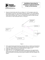
Figure 1-1: Illustration of a standard OMU II MBF Remote Application

MBF-40 AMERICAS REPEATERS
PRODUCT DESCRIPTION AND USER’S MANUAL
www.cobham.com/wireless
Page | 1-2
Date: 14-Feb-16
Rev. 4.3
Cobham Wireless – Coverage
Document number: 00071UM
1.1 Features and Capabilities
• High output power
• High efficiency MCPA amplifier technology
• Advanced and user-friendly remote control and supervision
• Up to four frequency bands in one enclosure
• Single enclosure MIMO support
• Up to 5 frequency bands over the same F/O cable ( 2 enclosures, master –slave configuration )
• Output power at the antenna (composite): 37dBm, 39dBm, 43dBm (model dependent)
• Very low noise factor - minimizes interference to BTS and increases high speed data throughput
• Single or Dual Fiber feed models available
• Remote commissioning and monitoring:
• Via OMU II intuitive Web GUI
• Via AEM – no local setup required
• SNMP v1/v2c support
• Plug-and-Play: Automatic detection and Optical Gain Setting via the OMU
• Automatic Level Control (ALC) - provides constant gain in both uplink and downlink paths
according to the defined maximum output level
• Automatic optical gain setting - he gain is adjusted in the downlink chain by measuring the level of the
pilot carrier sent from the Optical Master Unit (OMU). The level of the received pilot carrier is
continuously monitored
• Backup battery for ‘last gasp’ indication (sending fault error before power failure)
• Optional - two internal power supplies provided for some models ensure robust unit operation
• Power source: 115VAC or -48V power (model dependent)

MBF-40 AMERICAS REPEATERS
PRODUCT DESCRIPTION AND USER’S MANUAL
Cobham Wireless – Coverage Date: 14-Feb-16 www.cobham.com/wireless
Document number: 00071UM Rev. 4.3
Page | 1-3
1.2 ALC
The repeater has a constant gain in both uplink and downlink paths. The repeater has a defined
maximum output level. If the input signal amplified by the gain set exceeds the set output limit, an
ALC (Automatic Level Control) loop is activated. This ALC ensures that the amplifier does not add
distortion to the radio signal. Below are examples of the ALC function for one and two carriers.
1.3 Operating Temperature
The MBF-40 is designed primarily for multi carrier purposes. If the repeater is run at full output
power over a long period of time, additional, external cooling may be required; this can take the
form of air-conditioning or an external fan assembly.
Specific
MBF-40 models, whose power consumption exceeds 400W, are provided with an additional
fan hood cooling assembly.
NOTE: The repeater is equipped with a power management function that steps down the power and,
if needed, fully shuts down the amplifier chains until temperature reaches normal values.
1.4 MBF-40 Management Web GUI
MBF-40 is remotely commissioned and monitored via an OMUII session. Local access to the unit is
not required for commissioning.
Additional configuration and troubleshooting options are available via a direct connection to the MBF-
40 IP address. A direct session can be opened locally or remotely.
NOTE: Direct remote communication requires connecting the MBF-40 to an Ethernet network.
Figure 1-2: MBF-40 Home Screen

MBF-40 AMERICAS REPEATERS
PRODUCT DESCRIPTION AND USER’S MANUAL
www.cobham.com/wireless
Page | 1-4
Date: 14-Feb-16
Rev. 4.3
Cobham Wireless – Coverage
Document number: 00071UM
1.5 MIMO Topology
MIMO configuration is supported by specific MBF-40 models. The physical casing of these models
supports two antenna ports and includes two (internal) optic conversion modules (see section
1.7.3.2).
MBF-40 MIMO topology requires an OMU II unit that supports at least two sectors. Two dedicated
optic Fibres are routed from the OMU II towards the MBF-40.
Where relevant, MIMO specific installation instructions are provided in the manual.
Figure 1-3: MIMO OMU II-MBF-40 Remote Application

MBF-40 AMERICAS REPEATERS
PRODUCT DESCRIPTION AND USER’S MANUAL
Cobham Wireless – Coverage Date: 14-Feb-16 www.cobham.com/wireless
Document number: 00071UM Rev. 4.3
Page | 1-5
1.6 Five-Band Configuration
Cost effective five-band support over a single fibre-optic is implemented using two MBF-units: MBF-
40 Slave unit and MBF-40 Master unit. The Master unit can be either tri-band or quad-band unit,
where the Slave provides single-band or dual-band support for a total of five bands.
All the services are routed to the Master unit via the optic fibre. The relevant (tri or quad) services
are filtered by the Master unit and forwarded along with the unfiltered Slave services towards the
Slave unit. At the Slave unit, the additional services are filtered and all five services are routed
towards the service antenna for distribution. Five-Band System installation instructions are provided
in section
2.4.
NOTE: The Web interface displays the five band service system as a single, 5-band unit. See Section
3.3.4. The connections between the two units are detailed in section 2.4.
The following figure shows a Master/Slave configuration. The figure below shows a five band
configuration implemented using a quad-band Master and single-band Slave. The example shows
connections for a configuration WITHOUT external alarms.
Figure 1-4: Example of Five-band Configuration

MBF-40 AMERICAS REPEATERS
PRODUCT DESCRIPTION AND USER’S MANUAL
www.cobham.com/wireless
Page | 1-6
Date: 14-Feb-16
Rev. 4.3
Cobham Wireless – Coverage
Document number: 00071UM
1.7 MBF-40 Basic Interfaces
NOTE: This section describes the interfaces for MBF-40 models supporting up to four services and
whose power consumption does not exceed 400W. MBF-40 models, supporting five services and with
power consumption exceeding 400W are described in the relevant sections in chapter
2.
The MBF unit provides several types of interfaces:
• Lock and screws for protection and security
• External service antenna and GND connections
• Internal connections for power, Fibre optics and alarm cables routed via openings in the chassis
• Internal USB and Ethernet connections for local setup via Web GUI
1.7.1 Securing the Unit
The repeaters are secured with two hex screws (M8) and can also be locked with a key.
NOTE: The two screws must be fully tightened. Failure to do so may affect the IP65 compliancy and
therefore any warranty.
Figure
1-5: Securing Single/Dual Band
Figure
1-6: Securing Tri/Quad Band
Screws
Lock
Screws
Lock

MBF-40 AMERICAS REPEATERS
PRODUCT DESCRIPTION AND USER’S MANUAL
Cobham Wireless – Coverage Date: 14-Feb-16 www.cobham.com/wireless
Document number: 00071UM Rev. 4.3
Page | 1-7
1.7.2 External Interfaces
The repeater’s interfaces are located on the underside. Two basic models are available: single and
dual service antennas.
NOTE: The external connections at the bottom of the repeater can be protected with a cover which is
screwed in place.
Figure 1-7: Single Service Antenna Figure 1-8: Dual/MIMO Service Antenna
The following table provides a description of the front panel ports and connections.
Port Description
Server Service antenna connection - DIN 7/16” connector, female
Optic SC/APC Fibre optic inlet through which the optic Fibre is routed for internal
connections (section
2.2.6).
For MIMO models – route the two Fibres via the Fibre port.
NOTE: Optic Fibre Conduit hose fitter may be pre-assembled.
Power
Plinth connection for routing power for internal connection (section
2.2.8.1)
Alarms Plinth connector for routing external alarms and relay wiring cable for internal
connections (section
2.2.9).
GND
Grounding lug (section
2.2.4)
Fibre Input
Power Alarms
Server antenna
Fibre Input
Power Alarms
Server antennas

MBF-40 AMERICAS REPEATERS
PRODUCT DESCRIPTION AND USER’S MANUAL
www.cobham.com/wireless
Page | 1-8
Date: 14-Feb-16
Rev. 4.3
Cobham Wireless – Coverage
Document number: 00071UM
1.7.3 Internal Interfaces
This section shows the internal interfaces for the MBF-40 repeater. It is required to open the
repeater during installation in order to connect the
power
,
optic fibres
and (optionally), the
external
alarms
. In addition, it is required to verify the
power and battery switches
are set to ON.
NOTE: The repeater is usually set up via an OMU II session. However, the user can open a direct
local connection to the repeater Control module (requires opening the repeater) in order to
troubleshoot or to set up the repeater parameters.
The repeater internal interfaces vary according to the repeater model. The model can include any
combination of the following:
• Single or dual clamshell enclosure, according to the bands
• A single or a dual power-supply;
• A single or dual antenna port;
• MIMO support;
1.7.3.1 Single Power Supply Dual Antenna Ports
The following figure provides an example of a repeater with a single power supply and two antenna
ports.
Figure
1-9: Example of Model Supporting a Single Power Supply and Dual Service Antenna Ports
F/O Converter LEDs and
optic connector to which
routed optic fibre is
connected (section 2.2.7)
Alarms and relay connections.
Refer to section 2.2.11 for
descriptions.
Controller module - USB local
setup connections. Refer to
section 6.3.1 for LED descriptions
PS and switches
See section 2.2.9
Rechargeable
backup battery
pack, see
2.2.9.6
Routing power
connections
( 2.2.9)
Antenna
connections

MBF-40 AMERICAS REPEATERS
PRODUCT DESCRIPTION AND USER’S MANUAL
Cobham Wireless – Coverage Date: 14-Feb-16 www.cobham.com/wireless
Document number: 00071UM Rev. 4.3
Page | 1-9
1.7.3.2 MIMO Model
The MIMO model includes two Service Antenna ports and two Optic Converter modules (shown
below). All other connections and interfaces are similar to the above models.
Figure 1-10: MIMO Model
1.7.3.3 Dual Power Supply Model
The figure below provides an
example
of a unit with a dual power supply. The internal view of your
unit may differ.
Figure
1-11: Example of Dual Power Supply Model
Dual Fibre
optic
connectors to which
routed optic Fibre
s are
connected (section
2.2.7)
PS 1 (and switches)
See section 2.2.9
PS 1 (and switches)
See section 2.2.9
Backup
batteries
Routing power
connections (
2.2.9)

/