Page is loading ...

CAUTION – RISK OF SHOCK – Disconnect Power at the main
circuit breaker panel or main fuse box before starting and during
the installation.
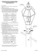
1) Slip fixture over post and mark position of mounting holes in post.
2) Remove fixture from post.
3) Drill 3/16” dia holes in post at positions marked .
4) If fixture is provided with ground wire, connect fixture ground
wire to outlet box ground wire with wire connector. (Not provided).
Never connect ground wire to black or white power supply wires.
5) Make wire connections (connectors not provided). Reference
chart below for correct connections and wire accordingly.
6) Slip fixture over post and secure in place using provided
screws. Screws should slip into holes drilled in post.
7) Insert recommended bulb.
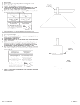
8) Place roof down on top of cage.
9) From the underside of the edge of the cage, thread screws
up through holes in edge of cage and into holes in roof.
Tighten screws to secure cage in place.
PRECAUCIÓN – RIESGO DE DESCARGA ELÉCTRICA – Desco-
necte la electricidad en el panel principal del interruptor automáti-
co o caja principal de fusibles antes de comenzar y durante la
instalación.
1) Deslice el artefacto sobre la columna y marque en ésta la
posición de los orificios donde montará el artefacto.
2) Retire el artefacto de la columna.
3) Perfore haciendo orificios de 3/16” de diámetro en las marcas
previamente hechas en la columna.
4) Si la lampara viene con alambre a tierra, conecte el alambre a
tierra del artefacto con el alambre a tierra de la caja de
conexiones utilizando el conector de alambre (no se provee).
Nunca conecte el alambre a tierra con el alambre de suministro
de potencia de color blanco o negro.
5) Haga las conexiones de alambres (no se provee conectores).
Consulte la tabla de abajo para hacer las conexiones correctas
y haga las conexiones omo corresponda.
6) Deslice el artefacto sobre la columna, fíjelo en su lugar usando
los tornillos que se proporcionan. Los tornillos deben entrar
perfectamente en los orificios que previamente perforó en la
columna.
7) Inserte la bombilla recomendada.
8) Coloque el techo hacia abajo en la parte superior de la jaula.
9) Desde la parte inferior del borde de la jaula, rosque los
tornillos a través de los agujeros en el borde de la jaula y en
los agujeros en el techo. Apriete los tornillos para asegurar el
jaula en su lugar.
Date Issued: 1/10/17 IS-49849-US
Connect Black or
Red Supply Wire to:
Connect
White Supply Wire to:
Black White
*Parallel cord (round & smooth) *Parallel cord (square & ridged)
Clear, Brown, Gold or Black
without tracer
Clear, Brown, Gold or Black
with tracer
Insulated wire (other than green)
with copper conductor
Insulated wire (other than green)
with silver conductor
*Note: When parallel wires (SPT I & SPT II)
are used. The neutral wire is square shaped
or ridged and the other wire will be round in
shape or smooth (see illus.)
Neutral Wire
Conectar el alambre de
suministro negro o rojo al
Conectar el alambre de
suministro blanco al
Negro Blanco
*Cordon paralelo (redondo y liso)
*Cordon paralelo (cuadrado y estriado)
Claro, marrón, amarillio o negro
sin hebra identificadora
Claro, marrón, amarillio o negro
con hebra identificadora
Alambre aislado (diferente del verde)
con conductor de cobre
Alambre aislado (diferente del
verde) con conductor de plata
*Nota: Cuando se utiliza alambre paralelo
(SPT I y SPT II). El alambre neutro es de forma
cuadrada o estriada y el otro alambre será de
forma redonda o lisa. (Vea la ilustracíón).
Hilo Neutral
We’re here to help 866-558-5706
Hrs: M-F 9am to 5pm EST
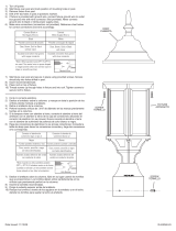
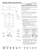
(3) SCREWS
WIRE CONNECTORS
CAGE
GLASS
SOCKET
FIXTURE ROOF
(2) FLAT-HEAD
ROOF SCREWS
POST CUP
(3) EMPULGUERAS
CONECTORES DE ALAMBRE
JAULA
VIDRIO
PORTALÁMPARAS
TECHNO DE LUMINARIA
(2) TORNILLOS DE TECHO
TAZA DE POST

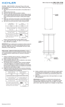
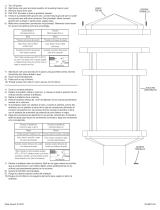
CAUTION – RISK OF SHOCK – Disconnect Power at the main
circuit breaker panel or main fuse box before starting and during
the installation.
1) Slip fixture over post and mark position of mounting holes in post.
2) Remove fixture from post.
3) Drill 3/16” dia holes in post at positions marked .
4) If fixture is provided with ground wire, connect fixture ground
wire to outlet box ground wire with wire connector. (Not provided).
Never connect ground wire to black or white power supply wires.
5) Make wire connections (connectors not provided). Reference
chart below for correct connections and wire accordingly.
6) Slip fixture over post and secure in place using provided
screws. Screws should slip into holes drilled in post.
7) Insert recommended bulb.
8) Place roof down on top of cage.
9) From the underside of the edge of the cage, thread screws
up through holes in edge of cage and into holes in roof.
Tighten screws to secure cage in place.
ATTENTION – RISQUE DE DÉCHARGES ÉLECTRIQUES – Couper
le courant au niveau du panneau du disjoncteur du circuit principal
ou de la boîte à fusibles principale avant de procéder à
l’installation.
1) Passer le luminaire par dessus le support et marquer un repère
pour les trous de montage sur le support.
2) Enlever le luminaire du support.
3) Percer des trous de 1/8 po sur chacun des repères du support.
4) Si luminaire est fourni a vec un fil de mise à la terre, le connecter
à la boîte de sortie de courant de mise à la terre avec un
serre-fils (non fourni). Ne jamais connecter un fil de mise à la
terre aux fils d’alimentation noir ou blanc.
5) Connecter les fils (connecteurs non fournis). Se porter au
tableau ci-dessous pour faire les connexions.
6) Faire glisser le luminaire sur le support et fixer à l’aide des vis.
Les vis doivent s’ajuster correctement dans les trous du
support.
7) Introduire l’ampoule recommandée.
8) Placer le toit vers le bas sur la partie supérieure de la cage.
9) Du dessous du bord de la cage, passer les vis par les trous
situés sur le bord de la cage puis dans les trous situés dans le
toit. Serrer les vis pour fixer la cage.
Date Issued: 1/10/17
IS-49849-CB
Connect Black or
Red Supply Wire to:
Connect
White Supply Wire to:
Black White
*Parallel cord (round & smooth) *Parallel cord (square & ridged)
Clear, Brown, Gold or Black
without tracer
Clear, Brown, Gold or Black
with tracer
Insulated wire (other than green)
with copper conductor
Insulated wire (other than green)
with silver conductor
*Note: When parallel wires (SPT I & SPT II)
are used. The neutral wire is square shaped
or ridged and the other wire will be round in
shape or smooth (see illus.)
Neutral Wire
Connecter le fil noir ou
rouge de la boite
Connecter le fil blanc de la boîte
A Noir A Blanc
*Au cordon parallèle (rond et lisse)
*Au cordon parallele (à angles droits el strié)
Au bransparent, doré, marron, ou
noir sans fil distinctif
Au transparent, doré, marron, ou
noir avec un til distinctif
Fil isolé (sauf fil vert) avec
conducteur en cuivre
Fil isolé (sauf fil vert) avec
conducteur en argent
*Remarque: Avec emploi d’un fil paralléle
(SPT I et SPT II). Le fil neutre est á angles
droits ou strié et l’autre fil doit étre rond ou
lisse (Voir le schéma).
Fil Neutre
INSTRUCTIONS
For Assembling and Installing Fixtures in Canada
Pour L’assemblage et L’installation Au Canada
We’re here to help 866-558-5706
Hrs: M-F 9am to 5pm EST
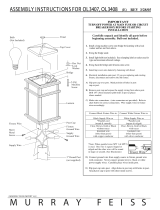
(3) SCREWS
WIRE CONNECTORS
CAGE
GLASS
SOCKET
FIXTURE ROOF
(2) FLAT-HEAD
ROOF SCREWS
POST CUP
(3) DES VIS
CONNECTEURS DE FIL
CAGE
VERRE
DOUILLE
TOIT DE LUMINAIRE
(2)VIS DE TOIT
COUPE POST
/

