Page is loading ...

© 2012 HeathCo LLC 204058-01A
DualBrite
®
Motion Sensor
Light Control
Model 5597
Light Control
2 Lamps
(installed)
Cover Plate
Sensor
Lamp Holders
This package includes:
TEST
TEST 1 5 20
ON-TIME
Off 3 6 Dusk to
Dawn
DualBrite
®
Put ON-TIME switch
on the sensor bottom
to TEST and the Dual-
Brite
®
switch OFF.
OPERATION
* resets to Auto Mode at dawn.
ON-TIME
TEST 1 5 20
... back on.
1 Second
OFF then...
Put the ON-TIME switch in the
1, 5, or 20 minute position.
Manual mode only works at night
because daylight returns the sensor
to AUTO.
Flip the light switch off for one sec-
ond then back on to toggle between
AUTO and MANUAL MODE.
Manual mode works only with the
ON-TIME switch in the 1, 5, or 20
position.
Note: When first turned on wait about 1
1
/
2
minutes for
the circuitry to calibrate.
Requirements
• Thelightcontrolrequires120-voltsAC.
• IfyouwanttouseManualMode,thecontrolmustbe
wired through a switch.
• Some codes require installation by a
qualified electrician.
• Thisproductisintendedforusewiththeenclosed
gasket and with a junction box marked for use in wet
locations.
Mode: On-Time Works: Day Night
Test
5 Seconds x x
Auto
1, 5, or 20 Min x
Manual
To Dawn* x
Accent
3, 6 Hr, to Dawn x
AUTO
MANUAL MODE
Features
• Turnsonlightingwhenmotionisdetected.
• Automaticallyturnslightingoff.
• DualBrite
®
Timer.
• Photocellkeepsthelightingoffduringdaylighthours.
• LEDindicatesmotionwassensed(dayornight).
Plastic Hanger
Rubber Plug
Gasket
6 Screws
(3 sizes included)
Mounting Strap
Mounting Bolt
2 Wire
Connectors

2
204058-01
Move ON-TIME Switch
to 1, 5, or 20 minutes
Mode Switching Summary
Flip light switch
off for one second
then back on*
MANUAL MODE
AUTO
TEST
* If you get confused while switching modes, turn the
power off for one minute, then back on. After the cali-
bration time the control will be in the AUTO mode.
DualBrite
®
Timer
Light comes on half bright for selected time after dusk
(Off, 3 hr., 6 hr., until dawn). Selecting OFF disables
this feature. The motion sensing features will continue
to work as described in this manual. If motion is sensed,
the light turns on full bright for the ON-TIME (1, 5, or
20 minutes) then returns to dim mode.
INSTALLATION
Foreavemountonly:
1. Swing the sensor head towards the clamp screw
joint.
If the sensor pops out of the ball joint, loosen the
clamp screw and push the sensor back into the ball
joint. Tighten the clamp screw when done.
2. Then rotate the sensor head clockwise 180° so the
controls face down.
Controls
For under eave installation, the sensor head must
be rotated as shown in the next two steps for proper
operationandtoavoidtheriskofelectricalshock.
Controls
Controls
Clamp Screw
CAUTION: To Avoid Fire Or Burn Hazards:
•Allowxturetocoolbeforetouching.Thebulband
the fixture operate at high temperatures.
• Keep xtureatleast2"(51 mm)fromcombustible
materials. Do not aim at objects closer than 3' (1 m).
• UseonlyT4100W(max.),G8tungstenhalogen
bi-pin 120 VAC bulbs.
CAUTION: Keep the sensor at least 2" (51 mm)
away from the bulbs.
For easy installation, select an existing light operated
by a wall switch for replacement. IMPORTANT: Do NOT
use with dimmers or timers.
For best performance, mount the fixture about 8 feet
(2.4m)abovetheground.NOTE: If fixture is mounted
higher than 8 feet (2.4 m), aiming the sensor down will
reducecoveragedistance.

3
204058-01
Keeplampsatleast2"(51mm)fromthe
sensorand2"(51mm)fromcombustibles.
Lock Nuts
Mount the Light Control
1. Place the mounting bolt through the front of the
junctionboxcover.Pushthesmallgasketholeover
the mounting screw.
2. Make sure the wire connectors and wires are inside
the junction box. Align the mounting screw with the
center hole in the mounting strap. Secure the fixture
to the mounting strap.
3. Push the rubber plug firmly into place.
4. If a wet location junction box was not used, caulk
the wall plate mounting surface with silicone weather
sealant.
Lamp Shade
Screw
5. Adjust the lamp holders by loosening the lock nuts,
but do not rotate the lamp holders more than 180°
from the factory setting.
6. Adjustlampshadesbylooseningthescrewsseveral
turns,turnshadescounterclockwiseandremove.
Reinstall the shades in the desired position and
tighten screws.
1. Removetheexistinglightxture.
2. Install the mounting strap as shown using two screws
that fit your junction box.
3. The plastic hanger can be used to hold the fixture
while wiring. The small end of the plastic hanger
can be threaded through the hole in the center of
thecoverplate.Thesmallendthengoesintoone
of the slots on the mounting strap.
4. Route the light control’s wires through the large
gasket holes.
5. Twist the junction box wires and fixture wires together
as shown. Secure with wire connectors.
White to
White
Black to
Black
Junction box ground wire to
green ground screw on fixture.
Gasket
Mounting
Strap
Mounting
Bolt
Rubber
Plug
Wire the Light Control
WARNING: Turn power off at circuit breaker
or fuse.
CAUTION: To avoid water damage and electrical
shock, keep lamp holders 30° below horizontal.
Screw

4
204058-01
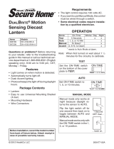
70 ft.
(21 m)
8 ft.
(2.4 m)
240°
Maximum Range Maximum
Coverage Angle
100 ft.
(30.5 m)
Boosted
Bottom of Sensor
Avoid aiming the control at:
•Objects that change temperature rapidly, such as
heating vents and air conditioners. These heat
sources could cause false triggering.
•Areaswherepets or traffic may trigger the control.
•Nearby large, light-colored objects reflecting light
may trigger the shut-off feature. Do not point other
lights at the sensor.
B
O
O
S
T
MAX
MIN
RANGE
ON - TIME DUAL BRITE
TEST 1 5 20
MINUTES
OFF 3 6 DUSK TO
HOUR DAWN
TEST AND ADJUSTMENT
1. Turn on the circuit breaker and light switch.
NOTE: Sensor has a 1
1
/
2
minute warm up period
before it will detect motion. When first turned
on, wait 1
1
/
2
minutes.
2. Turn the RANGE control to the minimum position
(MIN), DualBrite
®
to OFF, and the ON-TIME control
to the TEST position.
MotionMotion
3. Loosen the clamp screw in the
sensor ball joint and gently
rotate the sensor.
4. Walk through the coverage
area noting where you are
when the lights turn on (also,
theLEDwillashseveraltimes
whenmotionisdetected).Move
the sensor head up, down, or
sidewaystochangethecover-
age area. Keep the sensor at
least 2" (51 mm) away from
the lamps.
5. Adjust the RANGE as needed.
RANGE set too high may
increase false triggering.
6. Secure the sensor head by
tightening the clamp screw.
Donotovertightenthescrew.
7. Set the amount of TIME you want the lights to stay
on after motion is detected (1, 5, or 20 minutes).
8. Set the DualBrite
®
switch to the amount of time after
duskyouwantthelightsonatlowlevel(Off,3,6
Hrs., Dusk-to-Dawn).
Clamp
Screw
Ball
Joint
Aim Sensor
Down for Short
Coverage
Aim Sensor
Higher for Long
Coverage
Least Sensitive Most Sensitive
Sensor
NOTE:
If fixture is mounted higher than 8 ft. (2.4 m), aiming
thesensordownwillreducecoveragedistance.
Thedetectorislesssensitivetomotiondirectlytowardsit.
WARNING - Risk of fire. Do not aim the bulbs
at a combustible surface within 3 ft. (1 m).

5
204058-01
SPECIFICATIONS
Range . . . . . . . . . . . . . Up to 70 ft. (21 m); 100 ft.(30.5
m)withRangeBoost.[varies
with surrounding tempera-
ture]
Sensing Angle . . . . . . . Up to 240°
Electrical Load . . . . . . . Up to 200 Watts Maximum
Incandescent (Up to 100 Watts
Maximum each lamp holder.)
PowerRequirements . . 120 VAC, 60 Hz
Operating Modes . . . . . TEST, AUTO and MANUAL
MODE
Time Delay . . . . . . . . . 1, 5, 20 minutes
DualBrite
®
Timer . . . . . 3, 6 hours, Dusk-to-Dawn
Replacement lamp . . . . T4 100W, G8 halogen bi-pin
120 VAC
HeathCoLLCreservestherighttodiscontinueprod-
ucts and to change specifications at any time without
incurring any obligation to incorporate new features in
productspreviouslysold.
POSSIBLE CAUSE
1. A lamp is positioned too close to the
sensor or pointed at nearby objects
that cause heat to trigger the sensor.
(Reposition the lamp away from the
sensor or nearby objects).
2. Light control is pointed toward a heat
sourcelikean airvent,dryervent,or
brightly-paintedheat-reectivesurface.
(Reposition sensor. Reduce Range).
3. Light control is in Manual Mode. (Switch
to Auto).
1. Heat or light from the lamps may be
turning the light control on and off.
(Reposition the lamps away from the
sensor).
2. Heat being reflected from other objects
may be affecting the sensor. (Reposi-
tion sensor).
3. Light control is in the Test mode and
warming up. (Flashing is normal under
these conditions. Turn Boost off).
1. Sensor is detecting its own lights.
(Reposition lamps to keep area below
the sensor relatively dark).
SYMPTOM
Lights stay
on continu-
ously.
Lights flash
on and off.
Lights flash
once, then
stay off in
Manual Mode.
SYMPTOM
Lights will
not come
on.
Lights come
on in day-
light.
Lights come
on for no
apparent
reason.
Lights turn
off too late
in Dusk-
to-Dawn
setting.
POSSIBLE CAUSE
1. Light switch is turned off.
2. Light is loose or burned out.
3. Fuse is blown or circuit breaker is turned
off.
4. Daylight turnoff is in effect (recheck after
dark).
5. Incorrect circuit wiring, if this is a new
installation.
6. Re-aimthesensortocoverdesiredarea.
1. Light control may be installed in a rela-
tivelydarklocation.
2. Light control is in Test. (Set control switch
to an ON-TIME position).
1. Light control may be sensing small
animals or automobile traffic (re-aim
sensor).
2. Range is set too high. (Reduce Range
setting).
3. DualBrite
®
Timer is on.
1. Sensorisinarelativelydarklocation.
(Relocate sensor, or use 3 hr or 6 hr
setting).
TROUBLESHOOTING GUIDE
Bulb Replacement
CAUTION: When replacing the bulb, turn power
off and let the fixture cool.
Important:Useacleangloveorclothwhenhandling
the new bulb. Use isopropyl (rubbing) alcohol to clean
the bulb if it is touched with your bare hands.
1. Toremovelampshade,loosenscrew2fullturns
withasmallphillips-headscrewdriver.Turnshade
counterclockwiseandremove.
2. Toremovebulb,pullstraightoutofxture.
3. To replace bulb, push bulb pins into lamp socket.
Check that the bulb is seated properly.
4. To reinstall lamp shade, place shade on fixture and
align notches on shade with tabs on fixture. Turn
clockwise. Tighten screw firmly.

6
204058-01
TWO YEAR LIMITED WARRANTY
Thisisa“LimitedWarranty”whichgivesyouspeciclegalrights.Youmayalsohaveotherrightswhichvaryfrom
statetostateorprovincetoprovince.
Foraperiodoftwoyearsfromthedateofpurchase,anymalfunctioncausedbyfactorydefectivepartsor
workmanship will be corrected at no charge to you.
Not Covered -Repairservice,adjustmentandcalibrationduetomisuse,abuseornegligence,lightbulbs,
batteries,andotherexpendableitemsarenotcoveredbythiswarranty.Unauthorizedserviceormodica-
tionoftheproductorofanyfurnishedcomponentwillvoidthiswarrantyinitsentirety.Thiswarrantydoes
notincludereimbursementforinconvenience,installation,setuptime,lossofuse,unauthorizedservice,or
return shipping charges.
ThiswarrantycoversonlyHeathCoLLCassembledproductsandisnotextendedtootherequipmentand
components that a customer uses in conjunction with our products.
THIS WARRANTY IS EXPRESSLY IN LIEU OF ALL OTHER WARRANTIES, EXPRESS OR IMPLIED,
INCLUDINGANYWARRANTY,REPRESENTATIONORCONDITIONOFMERCHANTABILITYORTHAT
THEPRODUCTSAREFITFORANYPARTICULARPURPOSEORUSE,ANDSPECIFICALLYINLIEUOF
ALL SPECIAL, INDIRECT, INCIDENTAL, OR CONSEQUENTIAL DAMAGES.
REPAIRORREPLACEMENTSHALLBETHESOLEREMEDYOFTHECUSTOMERANDTHERESHALL
BENOLIABILITYONTHEPARTOFHEATHCO LLCFORANYSPECIAL,INDIRECT,INCIDENTAL,OR
CONSEQUENTIALDAMAGES,INCLUDINGBUTNOTLIMITEDTOANYLOSSOFBUSINESSORPROF-
ITS,WHETHERORNOTFORESEEABLE.Somestatesorprovincesdonotallowtheexclusionorlimitation
ofincidentalorconsequentialdamages,sotheabovelimitationorexclusionmaynotapplytoyou.Please
keep your dated sales receipt, it is required for all warranty requests.
TECHNICAL SERVICE
Please call 1-800-858-8501 (English speaking only) for assistance before returning
product to store.
Ifyouexperienceaproblem,followthisguide.YoumayalsowanttovisitourWebsiteat:www.hzsupport.com.
If the problem persists, call* for assistance at 1-800-858-8501 (English speaking only), 8:00 AM to 5:00 PM CST
(M-F).Youmayalsowrite*to:
HeathCo LLC
P.O. Box 90045
BowlingGreen,KY42102-9045
ATTN:TechnicalService
*IfcontactingTechnicalService,pleasehavethefollowinginformationavailable:ModelNumber,DateofPur-
chase, and Place of Purchase.
No Service Parts Available for this Product
Please keep your dated sales receipt, it is required for all warranty requests.

19
204058-01
Notes / Notas _________________
_____________________________
_____________________________
_____________________________
_____________________________
_____________________________
_____________________________
_____________________________
_____________________________
_____________________________
_____________________________
_____________________________
_____________________________
_____________________________
_____________________________
_____________________________
_____________________________
_____________________________
_____________________________

20
204058-01
Staple Purchase Receipt Here
Engrape aquí el recibo de compra
Agrafez le reçu d’achat ici
PLEASE KEEP YOUR DATED SALES RECEIPT,
IT IS REQUIRED FOR ALL WARRANTY REQUESTS.
POR FAVOR GUARDE SU RECIBO DE VENTA FECHADO; SE LO
REQUIERE PARA CUALQUIER SOLICITUD DE GARANTÍA.
VEUILLEZ CONSERVER LE REÇU PORTANT LA DATE D'ACHAT;
VOUS EN AUREZ BESOIN POUR TOUTES VOS DEMANDES
LIÉES À LA GARANTIE.
Purchase Information
Información de la compra
Renseignements d’achat
Model #: _________________ Date of Purchase: _____________
Nº de modelo / N° de modèle Fecha de compra / Date d’achat
/