Page is loading ...

Type OJ Microline OTN
INSTRUCTIONS
English
O
J Microline, electronic thermostat for
mounting in standard wall box. The thermostat
i
s adjustable to required temperature from
+
5/+40˚C. The LED shows that the heat is ON.
OJ MICROLINE PRODUKTPROGRAM
O
TN-1991H11 with floor sensor
OTN-1999H with built-in sensor
C
E MARKING
O
J declare under their own responsibility that
this product meets the requirements of the
European Council's directive 89/336 and
s
uccessive modifications as to electro-magnetic
c
ompatibility and the Council directive 73/23 as
to electrical equipment to be applied within
c
ertain voltage ranges.
Standards applied
EN 61000-6-3, EN 61000-6-2, EN 60 730-1 and
E
N 60730-2-9.
T
he product may only be energised when the
entire installation meets the current directive
r
equirements.
When the product is installed according to this
instructions guide and the current installation
guidelines, it is covered by factory guarantee.
If the product has been exposed to damage e.g.
in transport, it must be checked and overhauled
by qualified staff before the product is
connected to the power.
TECHNICAL DATA
Voltage . . . . . . .230V AC +10/-15%, 50/60 Hz
Current consumption . . . . . . . . . . . . . . . . . .6 VA
Max. fuse . . . . . . . . . . . . . . . . . . . . . . . . . . .16A
Built-in switch . . . . . . . . . . . . . . . . . .1-pole, 16A
Output relay - make contact . . . . . . . .SPST-NO
Load:
OTN-1991H11 . . . . . . . . .14A, 3200W
OTN-1999H . . . . . . . . . . . .16A, 3600W
Regulation principle . . . . . . . . . . . . . . . .ON/OFF
Temperature scale . . . . . . . . . . . . . . . .+5/+40°C
Difference/hysteresis . . . . . . . . . . . . . . . . .0.4°C
Setback temperature . . . . . . . . . . . . . .fixed 5˚C
- control voltage signal . . . . . . . . . . . . .230V AC
Scale limitation . . . . . . . . . . . . . . . . . .min./max.
Error circuit fuse at . . . . . . . . . . . . . . . . . .-20°C
Ambient temperature . . . . . . . . . . . . . . .0/+25°C
Dimensions . . . . . . . . . . .H/80, W/80, D/50 mm
Protection:
OTN-1991H11 . . . . . . . . . . . . . . . .IP21
OTN-1999H . . . . . . . . . . . . . . . . . .IP20
Because of tolerances the temperature range
may vary from +5/+45°C.
The thermostat is free of maintenance.
CLASSIFICATION
The product is a class II device (reinforced
insulation) and the product must be connected
to the following conductors:
1) Phase (L)
2) Neutral (N)
WARNING – Important Safety Instructions
Isolate supply before carrying out any
installation or maintenance work on this control
unit and associated components. This control
unit and associated components should only be
i
nstalled by a competent person (i, e qualified
e
lectrician). Electrical installation to be in
accordance with latest IEE Wiring Regulations
a
nd appropriate Statutory Regulations.
M
ounting of sensor
Floor sensor: Placed in an approved non
c
onductive installation pipe in accordance with
E
N 61386-1, which is embedded in the floor.
(fig. 4) The pipe is closed in the end and placed
as high as possible in the concrete layer. The
i
nstallation pipe must be centered in between
t
he heating cable.
Sensor cable can be extended up to 100 m. by
means of a separate cable. If the extension
c
able is lighter than H05VV-F, it shall equally be
i
nstalled in an unbroken installation pipe
between the sensor cable and the extension
c
able. Two remaining cores of a multi-core
c
able which, for example, supplies current to
the floor heating wires, must not be used. The
switching peaks of such current supply lines
m
ay create interfering signals that prevent
o
ptimum controller function. If a shielded cable
is used, the shield must not be earthed but
m
ust be connected to terminal 7. The two-core
cable must be placed in a separate pipe.
PLACEMENT OF THERMOSTAT WITH BUILT-
IN SENSOR
Thermostat is to be mounted on the wall with
free air circulation around it (fig. 5). Furthermore
it has to be placed where it is not influenced by
any other heating sources (e.g. the sun), draft
from doors or windows, or by the temperature
of an exterior wall.
OJ Microline units contain a fault interrupter
circuit which interrupts the heating in case of
disconnected or short-circuited sensors.
MOUNTING OF THERMOSTAT (fig. 1-3)
1. Remove the control knob (A).
2. Screw (B) should be unscrewed and the
cover lifted off.
3. Electrical connections can be made as
shown in the wiring diagram.
4. Mount the backing plate. Use only the round
holes.
5. The thermostat can now be filled into the
wall box.
- frame and cover is mounted
- thermostat knob is replaced
SETBACK TEMPERATURE
Setback of temperature setting is activated by a
230 V (L) signal from an external time switch to
terminal 5. Setback temperature is fixed 5˚C.
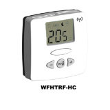
TEMPERATURE SETTING
OJ Microline has a scale range of +5/+40˚C. To
assist the adjustment, the thermostat has a LED
(D) which will glow RED when the heating is ON.
The thermostat should be set to maximum
temperature setting until the desired
temperature of the room or floor is achieved.
The control knob should then be turned back
until the LED goes out. Fine adjustments can be
made over the next 1/2 days to suit individual
requirements.
THERMOSTAT ADJUSTMENT
When the room temperature has been
stabilized, the thermostat set position may be
adjusted to match actual room temperature.
M
easure the temperature of the room with an
a
ccurate thermometer. Remove control knob
and reposition it so that the indicated
t
emperature line shows the same as the
m
easured temperature. This adjustment can be
d
one in steps of 3°C.
M
AX./MIN. TEMPERATURE
A
locking mechanism is positioned behind the
control knob to limit the amount of adjustment
possible. By loosening the little screw (C), the
s
cale range can be locked, e.g. between 20˚C
a
nd 25˚C. The red ring indicates the maximum
temperature and the blue ring indicates the
minimum temperature.
F
IGURS
Fig. 1 OJ Microline cover with knob.
F
ig. 2 Connection of OTN-1991H11 .
F
ig. 3 Connection of OTN-1999H.
Fig. 4 Mounting of floor sensor.
Fig. 5 Mounting of thermostat.
F
ig. 6 Scheme with sensor values.
Dansk
OJ Microline, elektronisk termostat for
montering i standard vægdåse. Termostaten
kan indstilles på ønsket temperatur fra
+5/+40˚C. Lysdiode viser at varme er indkoblet.
OJ MICROLINE PRODUKTPROGRAM
OTN-1991H11 med gulvføler
OTN-1999H med indbygget føler
CE MÆRKNING
OJ Electronics A/S erklærer under ansvar, at
dette produkt opfylder Rådets Direktiv 89/336
og efterfølgende ændringer om
elektromagnetisk kompatibilitet samt Rådets
Direktiv 73/23 og efterfølgende ændringer om
elektrisk materiel bestemt til anvendelse inden
for visse spændingsgrænser.
Anvendte standarder
EN 61000-6-3, EN 61000-6-2, EN 60 730-1 og
EN 60730-2-9.
Produktet må kun tages i brug, når hele
installationen opfylder gældende direktivkrav.
Når produktet er installeret i henhold til denne
vejledning og gældende installationsforskrifter,
er den omfattet af fabriksgaranti.
Hvis produktet har været udsat for fysisk
overlast eller beskadigelse, f.eks. under
transport, skal produktet efterses og kontrolleres
af kvalificeret personale før produktet tilsluttes
forsyningsnettet.
TEKNISKE DATA
Spænding . . . . . .230V AC +10/-15%, 50-60 Hz
Eget forbrug max. . . . . . . . . . . . . . . . . . . . .6 VA
Max. forsikring . . . . . . . . . . . . . . . . . . . . . . .16A
Indbygget afbryder . . . . . . . . . . . . .1-polet, 16A
Udgangsrelæ . . . . . .Sluttekontakt - SPST - NO
Udgangsstrøm:
OTN-1991H11 . . . . . . . . .14A, 3200W
OTN-1999H . . . . . . . . . . . .16A, 3600W
1
5
7943C - 10/12 (KPA)
© 2012 OJ Electronics A/S · ® The OJ trademark is a registred trademark belonging to OJ Electronics A/S
57943C.qxp:57943 08/10/12 11:47 Side 1

BR0898A07b
F
ig. 1
BR0898A07b
BR898A05a
1
MAX
1
4A
230
V
AC
L
N
L
234567
F
ig. 2 - OTN-1991H11
BR0898A05a
BR898A05a
1
MAX
1
6A
230
V
AC
L
N
L
2
345
Fig. 3 - OTN-1999H BR0898A06a
BR898A03a
F
ig. 4
B
R0898A03a
F
ig. 5
BR0929A04a
Fig. 6 BR0898A08a
-10
0
10
20
30
64000
38000
23300
14800
9700
Value (ohm)
Tipo ETF-.99
Temp. (°C)
BR0898A08a
OJ Electronics A/S
Stenager 13B · DK-6400 Sønderborg
TEL +45 73 12 13 14 · FAX +45 73 12 13 13
[email protected] · www.oj.dk
11
© 2012 OJ Electronics A/S
57943C.qxp:57943 08/10/12 11:47 Side 11

© 2012 OJ Electronics A/S - ® The OJ trademark is a registred trademark belonging to OJ Electronics A/S
12
57943C.qxp:57943 08/10/12 11:47 Side 12
/