PST105

ABB PST105 Installation And Commissioning Manual

  • Hello! I am an AI chatbot trained to assist you with the ABB PST105 Installation And Commissioning Manual. I’ve already reviewed the document and can help you find the information you need or explain it in simple terms. Just ask your questions, and providing more details will help me assist you more effectively!
P
o
w
e
r
o
n
P
r
o
t
e
c
t
i
o
n
F
a
u
lt
P
o
w
e
r
o
n
P
r
o
t
e
c
t
i
o
n
F
a
u
l
t
P
o
w
e
r o
n
P
r
o
te
c
t
io
n
Fault
P
o
w
e
r
o
n
P
r
o
t
e
c
t
i
o
n
F
a
u
l
t
P
o
w
e
r o
n
P
r
o
t
e
c
t
i
o
n
F
a
u
lt
Softstarters
Type PST30...PSTB1050
Installation and Commissioning Manual
Manual 1SFC132003M0201 June 2007
This manual belongs to:
Softstarters
Type PST30...PSTB1050
Installation and Commissioning Manual
Manual 1SFC132003M0201 June 2007
5
1SFC132003M0201
Installation and Commissioning Manual
PST30...PSTB1050
1 General
This is the Installation and commissioning manual for Softstarters
PST30...PSTB1050 based on software version CU 05.02.xx
(see STATUS INFORMATION menu)
Document number: 1SFC132003M0201
Edition: 04
Revision: 03
Issue date: 2007-06-29
Data subject to change without notice.
We reserve all rights to this document, even in the event that a patent is issued and
a different commercial proprietary right is registered. Improper use, in particular
reproduction and dissemination to third parties, is not permitted.
This document has been carefully checked. If the user nevertheless detects any
errors, he is kindly asked to notify us as soon as possible.
The data contained in this manual is intended solely for the product description and
is not to be deemed to be a statement of guaranteed properties. In the interests of
our customers, we constantly seek to ensure that our products are developed to the
latest technological standards.
As a result, there may be some differences between the softstarter and the
information in this manual.
Authors address:
ABB Automation Products, Cewe-Control
S-721 61 Västerås
Sweden
Tel: +46 (0) 21 32 07 00
Fax: +46 (0)21 12 60 01
http://www.abb.com/lowvoltage
© ABB Automation Technologies, Div. Automation Products, Cewe-Control
6
1SFC132003M0201
2 Safety
This chapter describes warning and information signs used in this manual, which
the user should pay attention to.
The softstarter shall be installed by authorized personnel only.
This manual is a part of the softstarter and should always be accessible to
personnel working with this product.
The manual shall always be read through before performing any installation or
commissioning tasks.
3 Safety signs
3.1 Use of Caution, Warning, and Information
Caution!
Caution icon indicates the presence of a hazard which could result in personal
injury.
Warning!
Warning icon indicates the presence of a hazard which could result in corruption
of software or damage to equipment/property.
Information sign alerts the reader to pertinent facts and conditions.
7
1SFC132003M0201
Chapter Page
1 Introduction 9
2 Quickstart 15
3 Description 19
4 Mounting 35
5 Connection 41
6 Human-Machine Interface (HMI) 61
7 Settings and configuration 75
8 Fieldbus communication (option) 119
9 Maintenance 123
10 Functions 127
11 Trouble shooting 177
12 Diagrams 189
13 Index 193
Customer feedback report 197
Chapter
8
1SFC132003M0201
Notes
..................................................................................................................................
..................................................................................................................................
..................................................................................................................................
..................................................................................................................................
..................................................................................................................................
..................................................................................................................................
..................................................................................................................................
..................................................................................................................................
..................................................................................................................................
..................................................................................................................................
..................................................................................................................................
..................................................................................................................................
..................................................................................................................................
..................................................................................................................................
..................................................................................................................................
..................................................................................................................................
..................................................................................................................................
..................................................................................................................................
.................................................................................................................................
9
1SFC132003M0201
Chapter 1 Introduction
About the complete set of documentation for a softstarter................................ 11
About the installation and commissioning manual ............................................ 11
Intended audience ....................................................................................... 11
General ................................................................................................... 11
Requirements ......................................................................................... 12
Chapters included ........................................................................................ 12
Revision notes ............................................................................................. 12
Acronyms and abbreviations........................................................................ 13
Introduction
Introduction
10
1SFC132003M0201
Introduction
Chapter 1
11
1SFC132003M0201
Chapter 1 Introduction
1:1 About the complete set of
documentation for a softstarter
For the softstarter, the following documents are available:
PST30...PSTB1050 Softstarters
Installation and Commissioning Manual
Document ID: 1SFC132003M0201
1SFC132003M2001 (Chinese)
1SFC132003M3101 (Dutch)
1SFC132003M1801 (Finnish)
1SFC132003M0301 (French)
1SFC132003M0101 (German)
1SFC132003M0901 (Italian)
1SFC132003M4001 (Polish)
1SFC132003M1601 (Portuguese)
1SFC132003M1101 (Russian)
1SFC132003M0701 (Spanish)
1SFC132003M3401 (Swedish)
1SFC132034M6501 (Thai)
1SFC132003M1901 (Turkish)
1SFC132003M2201 (US version)
Catalog Softstarters
Document ID: 1SFC132004C0201
For other documents related to the PST Softstarters, see
home page www.abb.com/lowvoltage
1:2 About the installation and
commissioning manual
This manual contains instructions on how to install and
commission the softstarter. The manual covers procedures
for mechanical and electrical installation, and installation of
communication devices. It also covers energizing, setting,
and configuration and verifying settings.
For quickest possible start read Chapter 2 “Quickstart” .
1:2.1 Intended audiences
1:2.1.1 General
The installation and commissioning manual is intended for
the installation, commissioning, and maintenance personnel
responsible for putting the softstarter into normal service and
out of service.
Introduction
Chapter 1
12
1SFC132003M0201
1:2.1.2 Requirements
The installation personnel must have a basic knowledge in
handling electric equipment. The commissioning and
maintenance personnel must be well experienced in using
this kind of equipment.
1:2.2 Chapters included
Introduction introduces the reader to this manual.
Quickstart contains information on how to, in the quickest
way, install the softstarter and put it into operation. This
chapter is intended for the experienced user.
Description describes the softstarter in general, its func-
tions and specifications.
Mounting contains information on receiving, unpacking
and mounting the softstarter.
Connection contains instructions on how to make the
electrical connections as well as connections for commu-
nication devices.
Human-Machine Interface describes the local Human-
Machine Interface, how it works, and what it contains.
Settings and configuration describes all possible settings
and how to navigate in the menu system.
Fieldbus communication describes how to install and set
up the fieldbus communication.
Maintenance describes what maintenance is needed.
Functions describes all functions included in the soft-
starter, as well as the available minimum and maximum
values and default values used.
Trouble shooting contains instructions on how to quickly
find and correct the most common faults.
Diagrams contain a number of electrical diagrams for the
softstarter itself, and also some typical application dia-
grams.
1:2.3 Revision notes
Please check home page
www.abb.com/lowvoltage
for latest information on revisions.
Introduction
Chapter 1
13
1SFC132003M0201
1:2.4 Acronyms and abbreviations
The following acronyms and abbreviations are used in this
manual.
Acronym/
abbreviation
Description
BP By-pass
DOL Direct-on-line
FB Fieldbus
FBP Fieldbusplug
HMI Human-Machine Interface
IT Information Technology
LCD Liquid Crystal Display
LED Light Emitting Diode
PCB Printed Circuit Board
PLC Programmable Logic Controller
PTC Positive Temperature Coefficient
SC Short Circuit
SCR Silicon Controlled Rectifier
TOR Top Of Ramp (full voltage)
Introduction
Chapter 1
14
1SFC132003M0201
15
1SFC132003M0201
Chapter 2 Quickstart
Connection........................................................................................................ 17
Configuration..................................................................................................... 18
Start of the motor .............................................................................................. 18
Quickstart
Quickstart
16
1SFC132003M0201
Quickstart
Chapter 2
17
1SFC132003M0201
Chapter 2 Quickstart
This chapter is a short guide to how to connect, do the
configuration and start the softstarter in the easiest way.
Warning!
Mounting, electrical connection and settings of the
softstarter shall be made in accordance with existing laws
and regulations and be performed by authorized personnel.
Do not change any parameters in the Service Settings
menu.
2:1 Connection
1. Mount the softstarter according to Chapter 4 “Mounting” .
2. Be aware of the ambient temperature.
Derating is required above 40
°C (104 °F).
3. Connect the main circuit: terminals 1L1 - 3L2 - 5L3 to the
line side and terminals 2T1 - 4T2 - 6T3 to the motor side.
4. Connect the supply voltage: terminal 1 and 2
(100-250V 50/60Hz).
5. Connect the functional ground: terminal 3.
The wire shall be as short as possible, and be connected to
the mounting plate. The mounting plate should also be
earthed.
6. Connect the start/stop circuits: terminal 4, 5, 8, 9, and 10
according to the diagram, with 24V DC.
Warning!
Terminal 4, 5, 6, 7, 8, 9, 10, and 11 should be connected
using
24V DC only. Other voltages may damage the
softstarter and the warranty may no longer be valid.
7. Check that the main and supply voltage corresponds to
the softstarter ratings.
8. Switch on the supply voltage.
9. The green "Power on" LED is on and the LCD shall
appear as in Figure 3.
Power on ProtectionFault
1
2
3
4
1SFC132029F0001
U= 0% I=0.0A
Menu
F
igure 1:
1 Status indication LEDs
2 LCD display
3 Selection keys for selecting, changing
and storing parameters
4 Navigation keys for navigating in the
menus
Arrows shown in the display indicates
that the value/menu is possible to
change or scroll
L1
L2
L3
N
KM1
1L1 3L2 5L3
2T1 4T2 6T3
12 13 14 15 16 17 18 19 20
U
V
W
12 3 4 5 6 7
89
10
45
10
11
M
3
24 V DC
1SFC132030F0001
F
igure 2: Standard connection PST
StartStop
Start
Stop
Power on ProtectionFault
F
igure 3: Top level
U= 0% I=0.0A
Menu
Quickstart
Chapter 2
18
1SFC132003M0201
2:2 Configuration
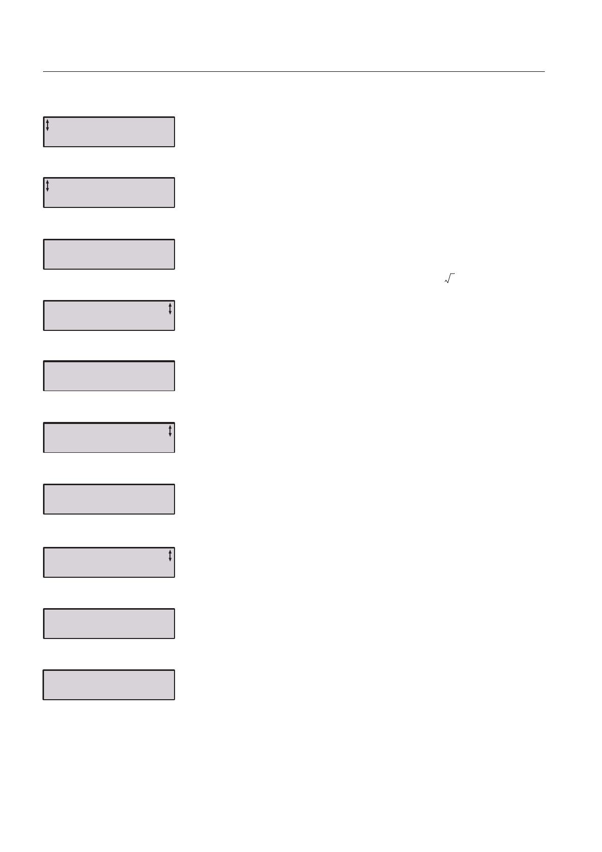
1. Enter the Application Setting by pressing left selection key
twice. Press Select using the left selection key. Figure 4.
2. Select the appropriate type of load using navigation keys.
Figure 5.
3. Press Store Set and Next to continue or Back to previous
parameter using the selection keys. Figure 6.
4. Set the Setting Ie using the navigation keys.
In Line connected = rated motor current
inside Delta connected = 58% ( ) of the rated
motor Icurrent. Figure 7.
5. Press Store and Next to continue or Back to previous
parameter using the selection keys. Figure 8.
6. Set the required overload class using the navigation keys.
Figure 9.
7. Press Store and Next to continue or Back to previous
parameter using the selection keys. Figure 10.
8. If an external by-pass contactor is used set Ext ByPass to
Yes using the navigation keys. (PST30...300 only).
Figure 11.
9. Press Store and Next to continue or Back to return to pre-
vious parameter using the selection keys. Figure 12.
10.Select Yes if ready or Tune Set if start/stop mode, ramp
types, initial/end voltage, current limits etc. needs to be
adjusted using selection keys. Figure 13.
11. To change presentation language, see section 7:2.5.
2:3 Start of the motor
1. Switch on the main voltage.
2. Give start command to the softstarter.
(To start the softstarter from the keypad, enter the LOCAL
CONTROL menu, select Start/Stop, and press Start. The
motor must be stopped before leaving this menu.)
Application Setting
Select Back
F
igure 4: Application setting menu
Centrifugal Pump
Store Set Back
F
igure 5: Centrifugal pump
Centrifugal Pump
Next Back
F
igure 6: Centrifugal pump stored
13()
Setting Ie 99.0A
Store
F
igure 7: Setting Ie
Setting Ie 99.0A
Next Back
F
igure 8: Setting Ie stored
OL Class 10
Store
F
igure 9: OL Class
OL Class 10
Next Back
F
igure 10: OL class stored
Ext ByPass No
Store
F
igure 11: External Bypass
Ext ByPass No
Next Back
F
igure 12: External Bypass stored
Ready?
Yes Tune Set
F
igure 13: Ready / Tune Set
19
1SFC132003M0201
Chapter 3 Description
Overview ........................................................................................................... 21
Functions .......................................................................................................... 22
Markings and connections ................................................................................ 24
Type designation............................................................................................... 25
Industrial
IT.................................................................................................................................... 25
Environmental influence.................................................................................... 26
Specifications .................................................................................................... 26
Technical data................................................................................................... 27
General ........................................................................................................ 27
Semi-conductor fuses .................................................................................. 27
Softstarter types........................................................................................... 28
Weights ........................................................................................................ 30
UL information.............................................................................................. 30
Dimensions .................................................................................................. 31
Description
Description
20
1SFC132003M0201
/