Page is loading ...
GVI dba Samsung CCTV
1621 West Crosby, Suite 104
Carrollton, TX 75006
PHONE : 866-492-8246
Printed in Korea
Part No. :14021-1205
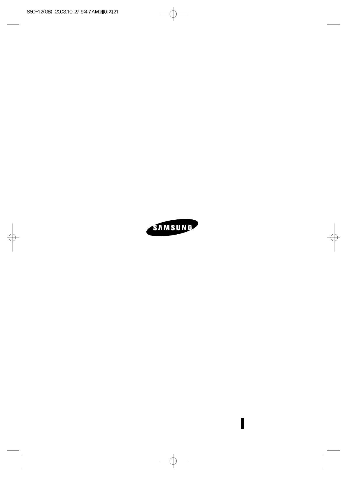
B/W OBSERVATION SYSTEM
Installation Manual
SSC-12
2
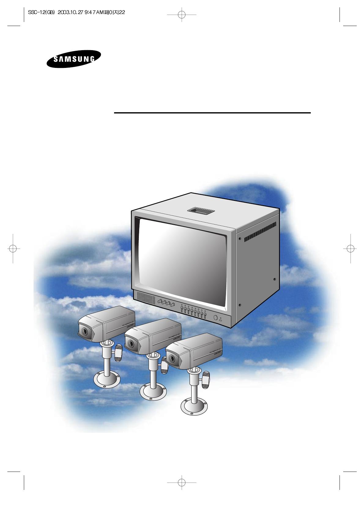
Graphic Symbol Explanation
The lightning flash with arrowhead symbol, within an
equilateral triangle, is intended to alert the user to the presence
of uninsulated ‘dangerous voltage’ within the product’s
enclosure that may be of sufficient magnitude to constitute a
risk of electric shock to persons.
The exclamation point within an equilateral triangle is
intended to alert the user to the presence of important
operating and maintenance (servicing) instructions in
the literature accompanying the appliance.
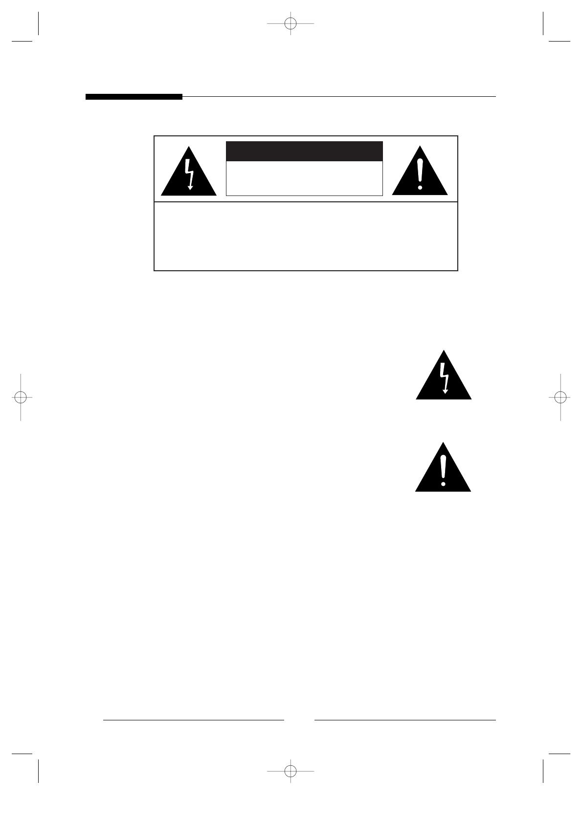
Warning - To Prevent Fire or Shock Hazard, Do Not
Expose This Monitor To Rain or Moisture.
CAUTION : TO REDUCE THE RISK OF ELECTRIC SHOCK, DO
NOT REMOVE COVER (OR BACK).
NO USER SERVICEABLE PARTS INSIDE. REFER
SERVICING TO QUALIFIED SERVICE PERSONNEL.
RISK OF ELECTRIC SHOCK
DO NOT OPEN
CAUTION
E
3
IMPORTANT SAFEGUARDS
Caution
Power source is indicated on the rear of the set. It contains high-voltage parts. If you
remove the cover, it may cause fire or electric shock. Do not remove the cover by yourself.
(Control switches are at the front of the monitor).
1. Read Instructions : All the safety and operating instructions should be read before
the appliance is operated.
2. Retain Instructions : The safety and operating instructions should be retained for
future reference.
3. Heed Warnings : All warnings on the monitor and in the operating instructions
should be adhered to.
4. Follow Instructions : All operating and use instructions should be followed.
5. Cleaning : Unplug this monitor from the wall outlet before cleaning. Do not use
liquid cleaners or aerosol cleaners. Use a damp cloth for cleaning.
Exception. A monitor that is meant for uninterrupted service and that for some
specific reason, such as the possibility of the loss of an authorization code for a
CATV converter, is not intended to be unplugged by the user for cleaning or any
other purpose, may exclude the reference to unplugging the monitor in the cleaning
description otherwise required in Item 5.
6. Attachments : Do not use attachments not recommended by SAMSUNG as they
may cause hazards.
7. Water and Moisture : Do not use this monitor near water for example, near a
bathtub, wash bowl, kitchen sink, or laundry tub, in a wet basement, or near a
swimming pool and the like.
8. Accessories : Do not place this monitor on an unstable cart, stand, tripod, bracket,
or table. The monitor may fall, causing serious injury to a child or adult, and
serious damage to the appliance. Use only with a cart, stand, tripod, bracket, or
table recommended by SAMSUNG, or sold with the monitor. Any mounting of the
monitor should follow SAMSUNG’s instructions, and should use a mounting
accessory recommended by SAMSUNG.
4
9. Ventilation : Slots and openings in the cabinet are provided for ventilation and to
ensure reliable operation of the monitor and to protect it from overheating, and
these openings should never be blocked by placing the monitor on a bed, sofa, rug,
or other similar surface. This monitor should never be placed near or over a
radiator or heat register.
This monitor should not be placed in a built-in installation such as a bookcase or
rack unless proper ventilation is provided or SAMSUNG’s instructions have been
adhered to.
10. Power Sources : This monitor should be operated only from the type of power
source indicated on the making label. If you are not sure of the type of power
supply to your installation site, consult your SAMSUNG dealer or local power
company.
11. Grounding or Polarization : For monitors equipped with a 3-wire grounding-type
plug having a third(grounding)pin. This plug will only fit into a grounding type
power outlet. This is a safety feature. If you are unable to insert the plug into the
outlet, contact your electrician to replace your obsolete outlet. Do not defeat the
safety purpose of the grounding-type plug.
12. Power : Cord Protection-Power supply cords should be routed so that they are not
likely to be walked on or pinched by items placed upon or against them, paying
particular attention to cords at plugs, convenience receptacles, and the point where
they exit from the monitor.
13. Lightning : For added protection for this monitor during a lightning storm, or
when it is left unattened and unused for long periods of time, unplug it from the
wall outlet and disconnect the cable system. This will prevent damage to the
monitor due to lightning and power-line surges.
14. Overloading : Do not overload wall outlets and extension cords as this can result
in a risk of fire of electric shock.
15. Object and Liquid Entry : Never push objects of any kind into this monitor
through openings as they may touch dangerous voltage points or short-out parts
that could result in a fire or electric shock.
Never spill liquid of any kind on the monitor.

16. Servicing : Do not attempt to service this monitor yourself as opening or removing
covers may expose you to dangerous voltage or other hazards. Refer all servicing
to qualified service personnel.
17. Damage Requiring Service : Unplug this monitor from the wall outlet and refer
servicing to qualified service personnel under the following conditions.
a. When the power-supply cord or plug is damaged.
b. If liquid has been spilled, or objects have fallen into the monitor.
c. If the monitor has been exposed to rain or water.
d. If the monitor does not operate normally by following the operating
instructions. Adjust only those controls that are covered by the operating
instructions as an improper adjustment of other controls may result in damage
and will often require extensive work by a qualified technician to restore the
monitor to its normal operation.
e. If the monitor has been dropped or the cabinet has been damaged.
f. When the monitor exhibits a distinct change in performance-this indicates a
need for service.
18. Replacement Parts : When replacement parts are required, be sure the service
technician has used replacement parts specified by SAMSUNG or have the same
characteristics as the original parts.
Unauthorized substitutions may result in fire, electric shock or other hazards.
19. Safety Check : Upon completion of any service or repairs to this monitor, ask the
service technician to preform safety checks to determine that the monitor is in
proper operating condition.
5
E

FCC & ICES Information
Warning
This equipment has been tested and found to comply with the limits for a class A
digital device, pursuant to part 15 of the FCC Rules and ICES-003 of Industry
Canada. These limits are designed to provide reasonable protection against harmful
interference when the equipment is operated in a commercial environment. This
equipment can radiate radio frequency energy and, if not installed and used in
accordance with the instruction manual, may cause harmful interference to radio
communications. Operation of this equipment in a residential area is likely to cause
harmful interference in which case the user will be required to correct the
interference at his own expense.
User-Installer Caution
Your authority to operate this FCC verified equipment could be voided if you make
changes or modifications not expressly approved by the party responsible for
compliance to part 15 of the FCC Rules.
6
E
7
Contents
IMPORTANT SAFEGUARDS..................................................... 3
1. System Components and Installation ........................................ 8
1-1. System Components........................................................... 8
1-2. System Configuration ........................................................ 9
1-3. Individual Component Installation................................... 10
1-4. Basic System Installation ................................................. 13
2. Connecting Peripheral Devices ............................................... 14
2-1. Connecting a PIR Sensor ................................................. 14
2-2. Connecting a VCR ........................................................... 14
3. Part Names and Functions....................................................... 15
3-1. Camera ..............................................................................15
3-2. Monitor Front................................................................... 16
3-3. Monitor Rear.................................................................... 18
4. Operation Function Instruction ............................................... 19
5. Technical Specifications.......................................................... 20
8
1. System Components and Installation
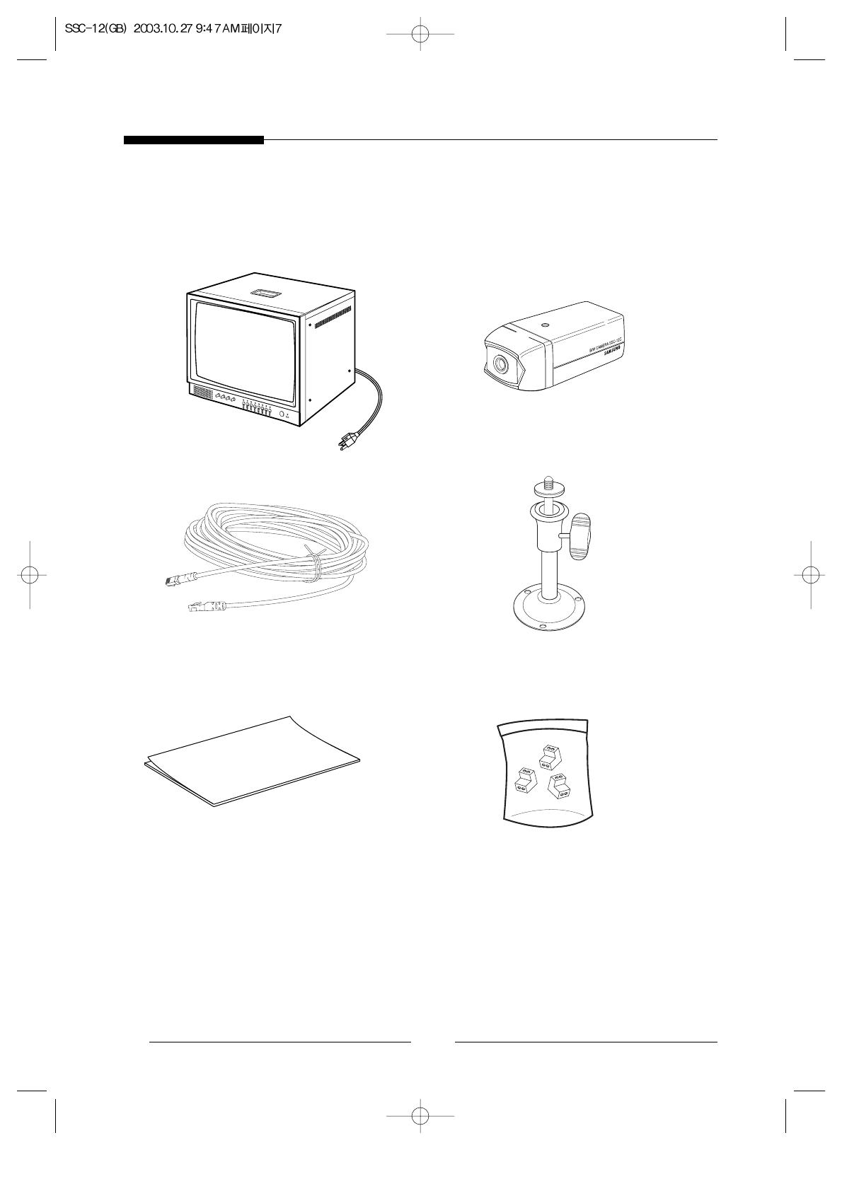
1-1. System Components
STANDARD CAMERA
CAMERA CABLE
MONITOR
CAMERA MOUNT BRACKET
INSTALLATION MANUAL
Alarm Terminal-BLOCK

E
9
1-2. System Configuration
Model Name Quantity Note
Monitor SSC-12M 1
Standard Camera SSC-12C 3
Camera Mount Bracket SBR-110 3
Camera Cable MCB-60 3
Installation Manual 1
10
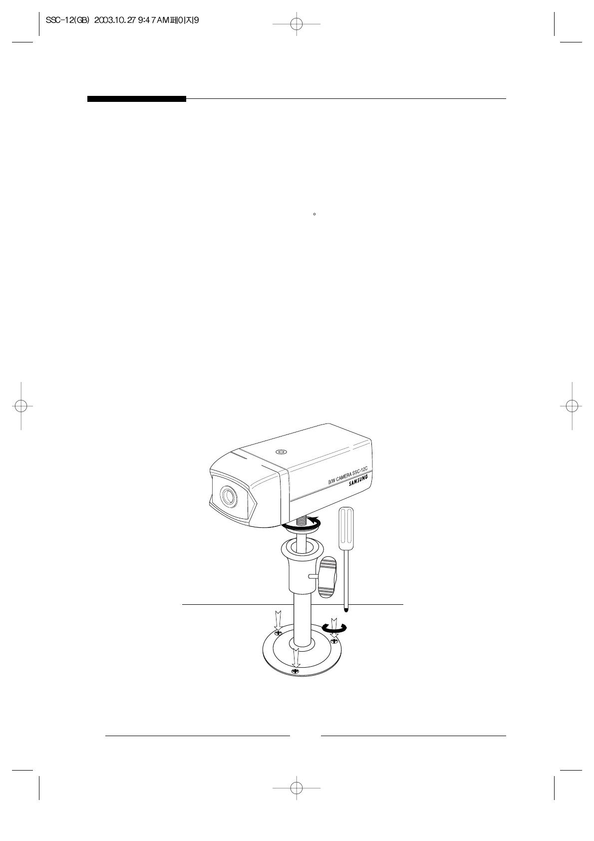
1-3. Individual Component Installation
1) INSTALLING STANDARD CAMERA (SSC-12C)
Caution to install SSC-12C outdoors
1. SSC-12C is designed to be protected from the water drops which are falling on the
upper side of camera in a range of 15
.
(Dust-water protection level : IP42)
Therefore, be sure to install it in a location which is fit in above condition when you
install it outdoor.
SSC-12C camera can be attached to the wall, ceiling or shelf using the camera
mount bracket (SBR-110).
●
Choose an installation site that can sufficiently support the weight of the equipments
to be installed.
●
Attach the camera mount bracket to the wall or ceiling using the supplied three screws
(M4 X L15).
●
Adjust the camera to target the video location and tighten the bracket handle on the
camera mount bracket.
4 ✕ 15 sized
screws
wall or ceiling
E
11
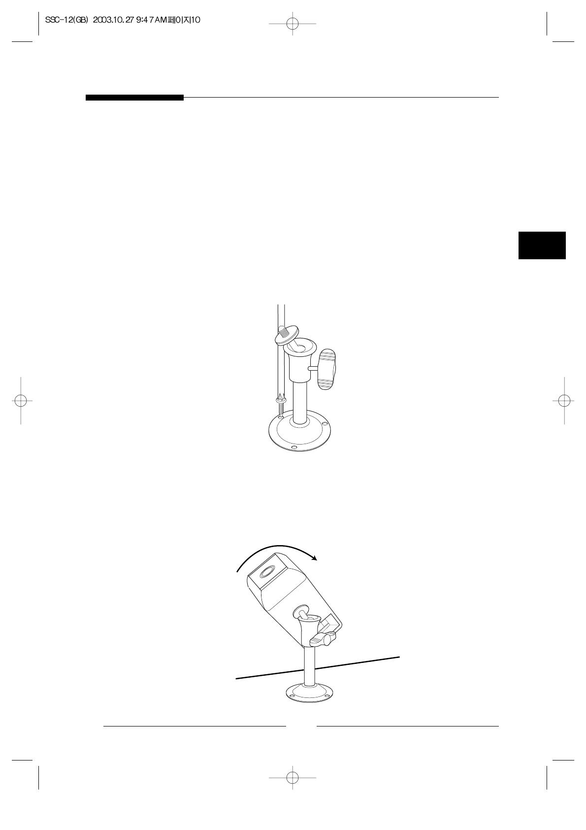
2) CAMERA MOUNT BRACKET(SBR-110) & STANDARD CAMERA
(SSC-12C)
! Overview
CAMERA MOUNT BRACKET (SBR-110) is used to attach the camera to
a wall, ceiling or shelf.
@ Installation
Explains the installation of CAMERA MOUNT BRACKET as well as the
installation of the camera onto the CAMERA MOUNT BRACKET.
●
Choose an installation site that can sufficiently support the weight of the
equipment to be installed.
●
Attach the camera mount bracket to the wall using the supplied screws
(M4 X L15).
●
Adjust the camera to target the video location and tighten the bracket handle on
the camera mount bracket. Install the camera onto the male
screw of the Camera Mount Bracket by rotating the camera in clockwise.
12
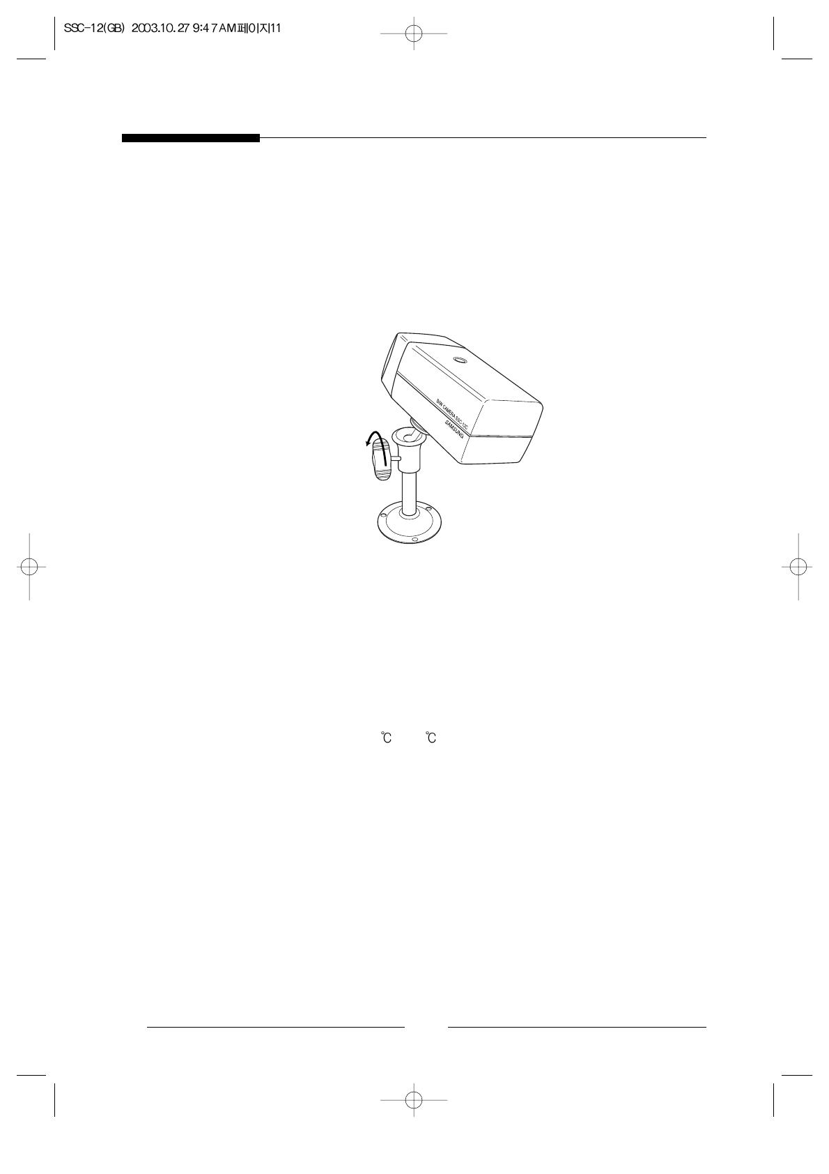
●
Loosen the handle by turning it in a counter clockwise direction and then adjust the
camera position. Tighten the handle, turning it clockwise, and lock the camera in
position.
●
Connect the camera cable to the camera.
# Specifications
Use : Indoor
Installation : Wall or Ceiling
Dimensions : 57(W) ✕ 47.2(H) ✕ 100.5(L)
Weight : 150g
Operating Temperature : -10
~ 50
$ Accessories
SCREW (M4 ✕ L15) 3 pcs
Handle
E
13
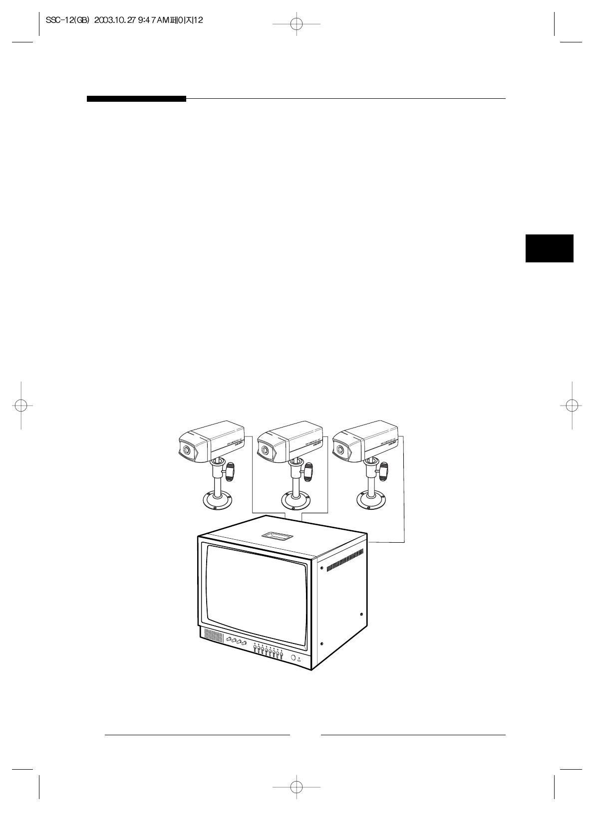
1-4. Basic System Installation
Perform the following steps to install your system.
●
Take the monitor out of the packaging box.
●
Place the monitor where you would like to install it. Do not turn on power until
installation is complete
●
Choose the place where you want to install the camera.
●
Once the monitor and camera locations have been chosen, install the camera.
●
Connect the cable to the jack on the back of the camera.
●
Connect the other end to CAMERA IN on the back of the monitor.
(At this time, select the numbers and sequence of cameras.)
●
Connect the camera you wish to install (as shown below).
●
Connect the power cord of the monitor to the power outlet.
●
Power switch is on the rear panel of the monitor, and screen on switch is on the front
panel of the monitor.
●
Initially the monitor is in the auto switching mode.
✳ After the power has been turned on, the CRT needs approximately 20 seconds of
stabilization period.

14
2. Connecting Peripheral Devices
2-1. Connecting a PIR Sensor
- An additional PIR sensor or external sensor can also be connected.
- The additional PIR sensor can be connected as shown in the above graphic.
- Sensor’s trigger signal is NO (Normal Open).
- Sensor is not supplied. (Sold separately)
2-2. Connecting a VCR
- Connect the VCR as shown below.
Mount on
the camera
Camera alarm in
jack
Sensor
Sensor
input
E
15
3. Part Names and Functions
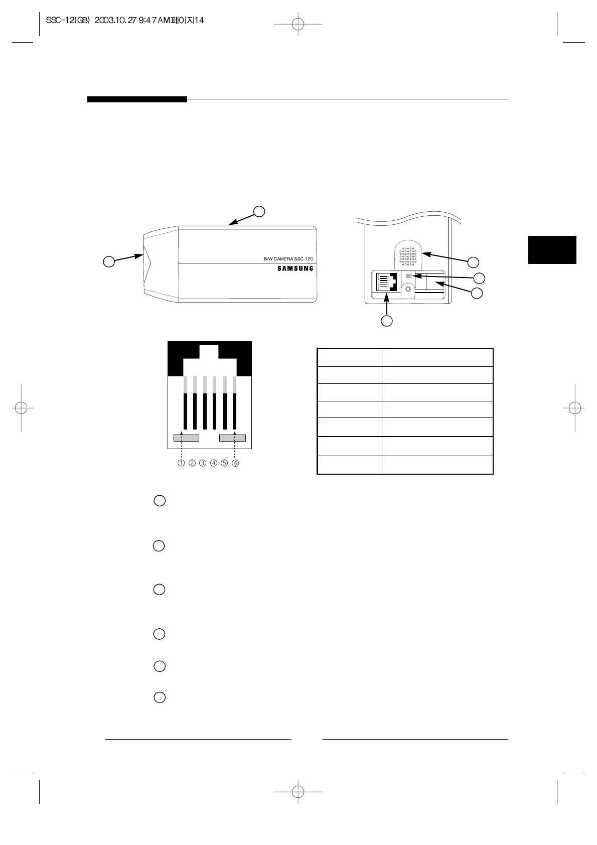
3-1. Camera
Standard Camera
Lens
It has a focal length of 3.8mm and makes it possible for you to observe a relatively
wide area.
Microphone
Capable of picking up all sound in the vicinity of the camera location and
transmitting to the monitor.
Camera fitting groove
Enables the camera to be fixed onto the bracket.
You may install it either above or below the camera if necessary.
6-pin modular jack
Used to connect the camera to the monitor.
SENSOR jack
Used to connect the sensor to the camera.
Speaker
It outputs the sound signal which was transfered from the monitor.
PIN NUMBER SPEC
1 SPEAKER(HOT)
2 VIDEO_OUT
3 GND
4 SPEAKER(COLD)
5 AUDIO_OUT/ALARM_OUT
6 12V DC
a
a
b
f
b
c
c
d
d
e
f
e

3-2. Monitor Front
! BRIGHT
●
Adjust brightness with this knob.
@ CONT.
●
Adjust contrast with this knob.
# AUDIO
●
Adjust volume control for proper sound level.
$ H-HOLD
●
This control permits adjustment of horizontal stability.
% TALK/A.RESET
●
TALK : Talk to selected channel.
●
A.RESET : Reset Alarm.
^ VCR
●
This button is used to display recorded data in the VCR on the monitor.
16

E
& AUTO
●
This monitor normally will be in AUTO mode, which means it switches cameras
automatically.
●
Press this button if you want to rescan camera port. This monitor will
automatically skip the cameras that are not connected, and the ALARM mode is
automatically activated in AUTO mode.
* CAMERA SELECT(C1~C4)
●
If you want press any camera selector button, this monitor goes into manual
mode. Press AUTO button if you want to return to auto mode.
( ALARM/TIME
●
ALARM : Press this button if you wish to enable or disable an alarm. Initial
mode of monitor is alarm enable mode.
(Red LED on : Alarm enabled)
●
TIME : Sequencing time(1 to 10 seconds) can be adjusted with this knob.
Go on pressing time button and press .
Ex) if you go on pressing time button and press 1S, 2S, 3S, the
switching time of screen will be 6 second.
) SCREEN ON/OFF
●
Turn the monitor screen ON/OFF. Even if the monitor is off, the system still
works for recording. Vertical spot line can be shown when turn off this switch.
1 POWER LED
●
MAIN Power LED.
17
18
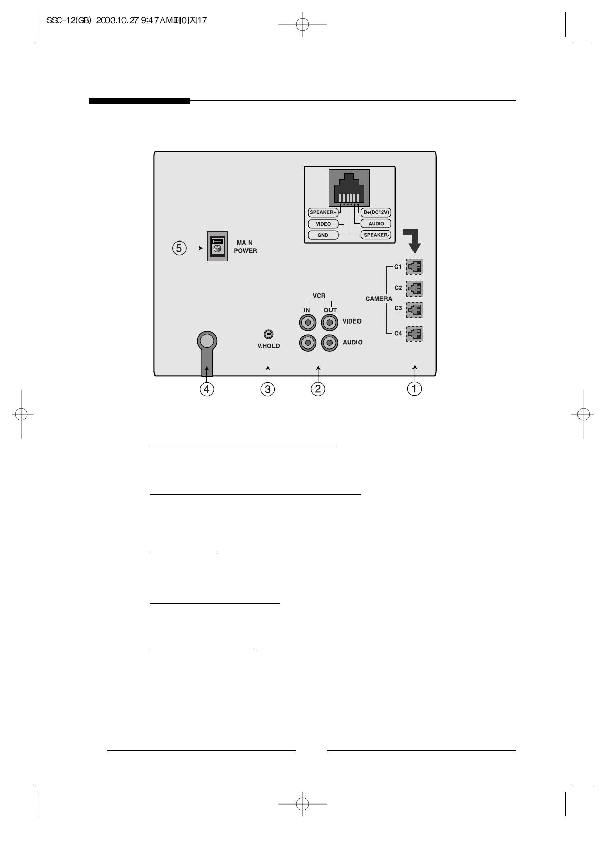
3-3. Monitor Rear
! CAMERA IN (CAM1~CAM4)
●
Four input ports for four cameras. (6 Pin Modular Jack)
@ AUDIO IN/OUT//VIDEO IN/OUT
●
AUDIO IN/OUT : Audio in/out ports for VCR recording and playing.
●
VIDEO IN/OUT : Video in/out ports for VCR recording and playing.
# V-HOLD
●
Use to correct when the picture rolls up and down.
$ AC POWER CORD
●
Power cord.
% MAIN POWER
●
Main power switch.
●
When power on, initial mode is switching screen.

E
19
4. Operation Function Instruction
! INITIAL STATUS
●
If you turn on this monitor, it search cameras.
●
If all cameras weren't connected to monitor, this screen display channel 1.
@ SEQUENTIAL SWITCHING MODE
●
Please press AUTO button, the monitor goes to sequential switching mode and the yellow
LED lamp of AUTO button will on.
●
The sequential switcher built in the monitor allows each camera to show the pictures
sequentially.
●
If a camera is disconnected from the monitor, it will be skipped and the deep sounds.
●
If camera 2 and camera 4 are connected to monitor, this is switched on sequence of camera
2, camera 4.
●
If all cameras were disconnected to monitor in AUTO mode, monitor displays channel 1.
●
The switching time can be adjusted from 1 to10 seconds by using time button.
●
Initial dwell time is 2 seconds.
●
If you want manually select camera, please press camera select button.
# ALARM FUNCTION
●
When the alarm is triggered, its signal goes to the monitor and the monitor shows the
triggered camera picture on the screen.
●
When two or more cameras are triggered at the same time, the monitor shows finally
triggered camera picture.
●
To reset alarm in case of alarm triggering, press TALK(A.RESET) key.
●
Once the alarm is released, the monitor goes back to the previous mode automatically.
●
If you make the alarm off in the VCR mode, the system doesn't go back to the VCR mode. It
goes back to more previous state than the VCR mode.
●
To disable the alarm completely(the alarm is not detected), set alarm lamp off by using alarm
button.
●
Alarm time is 12 seconds.
$ VCR MODE
●
To see the recorded picture, press the VCR key on the system
% AUDIO SYSTEM
●
This monitor has two way audio system.
●
When a camera picture appears on the screen, you can hear the sound from the camera's
microphone though the speaker built in the monitor.
●
If you want to talk to camera 2, please select it and go on pressing TALK button and talk.
/