Vega VEGAFLEX 83 Product information

Type
Product information

This manual is also suitable for

Vega VEGAFLEX 83 is a versatile guided wave radar level sensor designed for accurate and reliable level measurement in challenging liquids, including aggressive and corrosive substances. Its key capabilities include:

  • Two variants: rod probe and cable probe, both with PFA coating for exceptional chemical resistance.
  • Hygienic fittings and polished version (Basle Standard) for applications in the food processing and pharmaceutical industries.
  • Level measurement up to 32 meters (105 feet) for the cable probe and 4 meters (13.12 feet) for the rod probe.
  • Accuracy of ±2 mm ensures precise level readings.
Product information
Guided Wave Radar
Level and interface measurement in liquids
VEGAFLEX 81
VEGAFLEX 83
VEGAFLEX 86
Document ID: 46597
2
Contents
Guided Wave Radar - Level and interface measurement in liquids
46597-EN-160921
Contents
1 Measuring principle ............................................................................................................................................................................................... 3
2 Type overview ......................................................................................................................................................................................................... 5
3 Instrument selection .............................................................................................................................................................................................. 8
4 Selection criteria .................................................................................................................................................................................................. 11
5 Housing overview ................................................................................................................................................................................................12
6 Mounting ............................................................................................................................................................................................................... 13
7 Electronics - 4 … 20 mA/HART - two-wire ......................................................................................................................................................... 14
8 Electronics - 4 … 20 mA/HART - four-wire ........................................................................................................................................................15
9 Electronics-ProbusPA ....................................................................................................................................................................................16
10 Electronics-FoundationFieldbus .....................................................................................................................................................................17
11 Electronics,Modbus,Levelmasterprotocol...................................................................................................................................................... 18
12 Adjustment ........................................................................................................................................................................................................... 19
13 Dimensions ...........................................................................................................................................................................................................21
Take note of safety instructions for Ex applications
Please note the Ex specic safety information that you can nd at www.vega.com and that comes with each instrument. In hazardous areas
you should take note of the appropriate regulations, conformity and type approval certicates of the sensors and power supply units. The sen-
sors must only be operated on intrinsically safe circuits. The permissible electrical values are stated in the certicate.
3
Measuring principle
Guided Wave Radar - Level and interface measurement in liquids
46597-EN-160921
1 Measuring principle
Measuring principle
High frequency microwave pulses are coupled onto a cable or rod and
guided along the probe. The pulse is reected by the product surface.
The time from emission to reception of the signals is proportional to the
distance of the level.
The instrument is supplied with the probe length (0 % and 100 %)
already adjusted. In most cases setup on site is not required. In any case,
you set up VEGAFLEX without medium. The shortenable, bare cable and
rod versions can be simply adapted to the local requirements, if neces-
sary.
Levelmeasurementinliquids
Density uctuations, steam generation or strong pressure and tempera-
ture uctuations do not inuence the measuring result. Also buildup on
the probe or the vessel wall do not inuence the measurement. This
makes VEGAFLEX simple in planning.
An ideal application is level measurement in a bypass tube or standpipe,
because even products with a dielectric constant below 1.6 can be reli-
ably measured. Weld seams, buildup and corrosion inside the tube do
not inuence the accuracy of the level measurement. Even if overlling
up to the process tting occurs, the measurement is reliable. VEGAFLEX
81 also oers a special solution for ammonia applications.
Dierent probes are available
Cable probes for applications in high vessels up to 75 m (246 ft)
Rod probes for applications in vessels up to 6 m (20 ft)
Coax probes for application in low viscosity liquids, with vessel instal-
lations, in vessels up to 6 m (20 ft) high
The measured quantity is the distance between process tting of the sen-
sor and product surface. Depending on the sensor version, the reference
plane is the seal surface on the hexagon or the lower side of the ange.
2
4
5
3
2
4
5
3
1 1
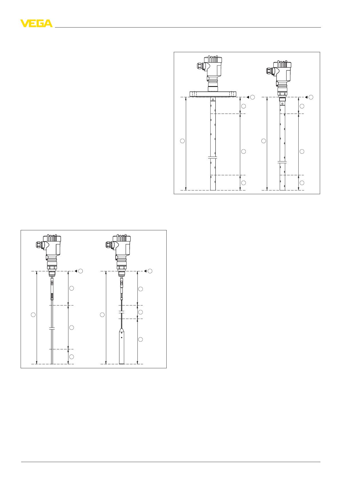
Fig. 1: Measuring ranges of the VEGAFLEX cable and rod versions
1 Reference plane
2 Probe length (L)
3 Measuring range
4 Upper dead band
5 Lower dead band
2
4
5
3
1
2
4
5
3
1
Fig. 2: Measuring ranges of VEGAFLEX - coax version
1 Reference plane
2 Probe length (L)
3 Measuring range
4 Upper dead band
5 Lower dead band
Interfacemeasurementinliquids
Non-conductive products only partly reect the energy of microwaves.
The non-reected energy passes through the medium and is reected
at the phase boundary to a second liquid. Interface measurement takes
advantage of this eect. You can select this function on VEGAFLEX via
the adjustment tools.
You thus get a reliable total level as well as the level of the lower medium
in your vessel.
Typical applications are interface measurements in storage tanks,
separators and pump sumps. VEGAFLEX normally determines the level
of water underneath a non-conductive medium. Since the instrument is
independent of the density of the medium, a reliable, maintenance-free
and precise measurement can be realised.
By simply switching over, the instruments can be used for interface
measurement of liquids.
Thanks to its guide tube, the coax version is not inuenced by vessel
installations and reliably measures products with low dielectric constant.
Therefore this instrument version is be preferred.
Prerequisitesforinterfacemeasurement
Uppermedium(L2)
The upper medium must not be conductive
The dielectric constant of the upper medium must be known
The composition of the upper medium must be stable, no varying
products or mixtures
The upper medium must be homogeneous, no stratications within
the medium
The layer can only be measured if it has a thickness ≥ 100 mm (4 in)
Clear separation from the lower medium, no emulsion phase, no
detritus layer
If possible, no foam on the surface
Lowermedium(L1)
The dielectric constant must be 10 higher than the dielectric constant
of the upper medium, preferably electrically conductive. Example:
upper medium dielectric constant 2, lower medium at least dielectric
constant 12
4
Measuring principle
Guided Wave Radar - Level and interface measurement in liquids
46597-EN-160921
TS
d1
h1
h2
d2
1
L2
L1
Fig. 3: Interface measurement
1 Reference plane
d1 Distance to the interface (HART value 1 or Primary Value)
d2 Distance to the level (HART value 3 or Third Value)
TS Thickness of the upper medium (d1 - d2)
h1 Height - Interface
h2 Height - Level
L1 Lower medium
L2 Upper medium
5
Type overview
Guided Wave Radar - Level and interface measurement in liquids
46597-EN-160921
2 Type overview
VEGAFLEX81
Cableversion
VEGAFLEX81
Rod version
VEGAFLEX81
Coax version
Applications Storage tanks, liquids with agitated sur-
face
Storage tanks, liquids with smooth sur-
face
Storage tanks, liquids with low dielectric
constant, vessel with installations
Max. measuring range
75 m (246 ft) 6 m (19.69 ft) 6 m (19.69 ft)
Probe Cable probe
ø 2 mm
ø 4 mm
Rod probe
ø 8 mm
ø 12 mm
Coax probe
ø 21.1 mm
ø 42.2 mm
Processtting Thread from G¾, ¾ NPT
Flanges from DN 25, 1"
Thread from G¾, ¾ NPT
Flanges from DN 25, 1"
Thread from G¾, ¾ NPT
Flanges from DN 25, 1"
Process temperature -40 … +200 °C (-40 … +392 °F) -40 … +200 °C (-40 … +392 °F) -40 … +200 °C (-40 … +392 °F)
Process pressure -1 … +40 bar/-100 … +4000 kPa (-
14.5 … +580 psig)
-1 … +40 bar/-100 … +4000 kPa (-
14.5 … +580 psig)
-1 … +40 bar/-100 … +4000 kPa (-
14.5 … +580 psig)
Measuring accuracy ±2 mm ±2 mm ±2 mm
Signal output
4 … 20 mA/HART - two-wire
4 … 20 mA/HART - four-wire
Probus PA
Foundation Fieldbus
Modbus and Levelmaster protocol
Indication/Adjustment
PLICSCOM
PACTwa re
VEGADIS 81
VEGADIS 62
Approvals
ATEX
IEC
Shipbuilding
Overll protection
FM
CSA
EAC (GOST)
6
Type overview
Guided Wave Radar - Level and interface measurement in liquids
46597-EN-160921
VEGAFLEX83
Cableversion
VEGAFLEX83
Rod version
VEGAFLEX83
Rodversion-Foodstus
Applications Aggressive and corrosive liquids Aggressive and corrosive liquids Hygienic applications in the food process-
ing and pharmaceutical industry
Max. measuring range
32 m (105 ft) 4 m (13.12 ft) 4 m (13.12 ft)
Probe Cable probe
ø 4 mm
PFA coated
Rod probe
ø 10 mm
PFA coated
Rod probe
ø 8 mm
Polished version (Basle Standard)
Processtting/Material Flanges from DN 25, 1"
Hygienic ttings
PTFE-TFM 1600
Flanges from DN 25, 1"
Hygienic ttings
PTFE-TFM 1600
Hygienic ttings
Process temperature
-40 … +150 °C (-40 … +392 °F) -40 … +150 °C (-40 … +302 °F) -20 … +150 °C (-4 … +302 °F)
Process pressure -0.5 … +16 bar/-50 … +1600 kPa (-
7.3 … +232 psig)
-0.5 … +16 bar/-50 … +1600 kPa (-
7.3 … +232 psig)
-1 … +40 bar/-100 … +4000 kPa (-
14.5 … +580 psig)
Deviation ±2 mm ±2 mm ±2 mm
Signal output
4 … 20 mA/HART - two-wire
4 … 20 mA/HART - four-wire
Probus PA
Foundation Fieldbus
Modbus and Levelmaster protocol
Indication/Adjustment
PLICSCOM
PACTwa r e
VEGADIS 81
VEGADIS 62
Approvals
ATEX
IEC
Shipbuilding
Overll protection
FM
CSA
EAC (GOST)
7
Type overview
Guided Wave Radar - Level and interface measurement in liquids
46597-EN-160921
VEGAFLEX86
Cableversion
VEGAFLEX86
Rod version
VEGAFLEX86
Coax version
Applications High temperature applications High temperature applications High temperature applications
Max. measuring range
75 m (246 ft) 6 m (19.69 ft) 6 m (19.69 ft)
Probe Cable probe
ø 2 mm
ø 4 mm
Rod probe
ø 16 mm
Coax probe
ø 42.2 mm
Processtting Thread G1½
Flanges from DN 40, 2"
Thread G1½
Flanges from DN 40, 2"
Thread G1½
Flanges from DN 40, 2"
Process temperature -196 … +450 °C (-321 … +842 °F) -196 … +450 °C (-321 … +842 °F) -196 … +450 °C (-321 … +842 °F)
Process pressure -1 … +400 bar/-100 … +40000 kPa (-
14.5 … +5800 psig)
-1 … +400 bar/-100 … +40000 kPa (-
14.5 … +5800 psig)
-1 … +400 bar/-100 … +40000 kPa (-
14.5 … +5800 psig)
Deviation ±2 mm ±2 mm ±2 mm
Signal output
4 … 20 mA/HART - two-wire
4 … 20 mA/HART - four-wire
Probus PA
Foundation Fieldbus
Modbus and Levelmaster protocol
Indication/Adjustment
PLICSCOM
PACTwa r e
VEGADIS 81
VEGADIS 62
Approvals
ATEX
IEC
Shipbuilding
Overll protection
FM
CSA
EAC (GOST)
8
Instrument selection
Guided Wave Radar - Level and interface measurement in liquids
46597-EN-160921
3 Instrument selection
Application areas
VEGAFLEX81
VEGAFLEX 81 is suitable for applications with liquids in small vessels
under ordinary process conditions. There are application possibilities in
nearly all areas of industry.
Through a large selection of gravity weights, the VEGAFLEX 81 can be
also used in standpipes and bypass tubes.
VEGAFLEX83
The PFA-coated VEGAFLEX 83 is suitable for measurement in aggres-
sive liquids or applications with special hygienic requirements. Applica-
tion possibilities can be found in the chemical industry as well as in the
food processing and pharmaceutical sector.
The polished version of VEGAFLEX 83 is particularly suitable for level
measurement under hygienic conditions in, for example, vessels with
foodstus.
VEGAFLEX86
VEGAPULS 86 is suitable for high temperature applicatons in liquids, e.g.
in storage tanks and process vessels. The application possibilities can be
found in the chemical industry, the environmental and recycling technol-
ogy as well as in the petrochemical industry.
Applications
Levelmeasurementinconicalvessels
During operation, the probe must not touch any installations or the vessel
wall. If necessary, fasten the probe end.
In vessels with conical bottom it can be advantageous to mount the sen-
sor in the center of the vessel, as measurement is then possible down to
the lowest point of the vessel bottom.
Fig. 13: Vessel with conical bottom
Measurementinastandpipeorbypasstube
When a standpipe or bypass tube is used in a vessel, the inuences from
vessel installations and turbulence can be excluded. In such case, meas-
urement of products with low dielectric values (ε
r
value ≥ 1.6) is possible.
In very adhesive products, measurement in a standpipe or bypass tube is
not recommended.
If VEGAFLEX is used in standpipes or bypass tubes, contact with the
tube wall should be avoided. We oer spacers as accessories for fasten-
ing the probe in the middle of the tube.
If chemical resistance is not a problem, we recommend using a metal
tube to improve measurement reliability.
1
Fig. 14: Position of the spacer
1 Spacer
Note:
Measurement in a standpipe is not recommended for extremely
adhesive products.
Interface measurement
Through simple switching, all instruments of the VEGAFLEX 80 series
can also measure liquid interfaces. Typical applications are the measure-
ment of oil or solvents on water. The measuring principle is maintenance-
free because no moving parts are used. VEGAFLEX operates completely
independent of the density of the product. This means reliable measured
values without additional eort for correction.
Prerequisitesforinterfacemeasurement
The upper medium must not be conductive
The dielectric constant of the upper medium must be known (input
required). Min. dielectric constant: rod version 1.7.
The composition of the upper medium must be stable, no varying
products or mixtures
The upper medium must be homogeneous, no stratications within
the medium
Min. thickness of the upper medium 100 mm
Clear separation from the lower medium, no emulsion phase, no
detritus layer
If possible, no foam on the surface
Lowermedium(L1)
The dielectric constant must be 10 higher than the dielectric constant
of the upper medium, preferably electrically conductive. Example:
upper medium dielectric constant 2, lower medium at least dielectric
constant 12
9
Instrument selection
Guided Wave Radar - Level and interface measurement in liquids
46597-EN-160921
TS
d1
h1
h2
d2
1
L2
L1
Fig. 15: Interface measurement
1 Reference plane
d1 Distance to the interface (HART value 1)
d2 Distance to the level (HART value 3)
TS Thickness of the upper medium (d1 - d2)
h1 Height - Interface
h2 Height - Level
L1 Lower medium
L2 Upper medium
Mounting socket
If possible, avoid sockets. Mount the sensor ush with the vessel top. If
this is not possible, use short sockets with small diameter.
Higher sockets or sockets with a bigger diameter can generally be used.
They can, however, increase the upper blocking distance (dead band).
Check if this is relevant for your measurement.
In such cases, always carry out a false signal suppression after installa-
tion. You can nd further information under "Setup procedure".
h
d
dh
DN25 ... DN150
> DN150 ... DN200
150 mm (5.91")
100 mm (3.94")
Fig. 16: Mounting socket
When welding the socket, make sure that the socket is ush with the
vessel top.
1 2
Fig. 17: Socket must be installed ush
1 Unfavourable installation
2 Socket ush - optimum installation
Plastic vessel/Glass vessel
The guided microwave principle requires a metallic surface on the
process tting. Therefore, in plastic vessels, etc., use an instrument ver-
sion with ange (from DN 50) or place a metal sheet (ø > 200 mm/8 in)
beneath the process tting when screwing it in.
Make sure that the plate has direct contact with the process tting.
When installing rod or cable probes in vessels without metal walls, e.g. in
plastic vessels, the measured value can be inuenced by strong electro-
magnetic elds (emitted interference according to EN 61326: class A). In
this case, use a probe with coaxial version.
1 2
Fig. 18: Installation in non-metallic vessel
1 Flange
2 Metal sheet
Ammonia applications
For applications in ammonia, a special, gas-tight instrument version of
VEGAFLEX 81 as coax probe is available.
For this special application, the instrument is equipped with high resistant
seals of elastomer-free materials. The instrument seal and the "Second
Line of Defense" are made of borosilicate glass GPC 540.
Steamboilerapplications
Vapours, superimposed gases, high pressures and temperature dier-
ences can change the spreading speed of radar impulses.
For automatic correction of these deviations, the VEGAFLEX can be
optionally equipped with a running time correction over the reference
distance. Hence the probe can execute an automatic running time cor-
rection.
The reference point must hence not be overlled. The upper dead band is
hence 450 mm (17.7 in).
10
Instrument selection
Guided Wave Radar - Level and interface measurement in liquids
46597-EN-160921
2
3
4
5
1
2
5
4
3
1
6
6
Fig. 19: Measuring ranges - VEGAFLEX with steam compensation
1 Reference plane
2 Probe length (L)
3 Measuring range
4 Upper dead band
5 Lower dead band
6 Additional upper dead band by steam compensation
7 Reference measurement distance to steam compensation
Autoclaved version
For use in an autoclave, e.g. for sterilization, the polished version of
VEGAFLEX is available as autoclavable version.
Hence you can separate the housing from the process tting.
The side of the process tting is provided with a cover after the housing
is removed.
After autoclaving, attach the housing again and the instrument is immedi-
ately ready for operation.
112 mm
(4.84")
DIN DN25 DN32 DN40 / 1" 1 1/2"
L
ø 54 mm
(2.13")
ø w
183 mm
(7.20")
65,3 mm
(2.57")
ø w
ø 50,5
DIN DN50 / 2" ø 64
ø 91DIN DN65 / 3"
2
1
3
Fig. 20: Autoclaved version
1 Groove nut
2 Process tting
3 Cover with groove nut
11
Selection criteria
Guided Wave Radar - Level and interface measurement in liquids
46597-EN-160921
4 Selection criteria
VEGAFLEX81 VEGAFLEX83 VEGAFLEX86
Cable Rod Coax Cable Rod Polished
rod
Cable Rod Coax
Vessel
Vessels < 6 m
High vessels > 6 m
Non-metallic vessels
Measurement in a standpipe or bypass tube
Process Aggressive liquids
Bubble or foam generation
Wave movements at the surface
Steam or condensation
Buildup
Changing density
Ammonia application
High temperatures > 200 °C
Pressures up to 400 bar
Hygienic applications
Narrow space above the vessel
Steam boiler application
Processtting Threaded ttings
Flange connections
Hygienic ttings
Probe Stainless steel
PFA coating
Polished (Basel Standard)
Probe can be shortened
Industry
Chemical
Power generation
Foodstus
Oshore
Petrochemical
Pharmaceutical
Shipbuilding
Environment and recycling industry
Water
Waste water
– not recommended
○ possible with limitations
● optimum suitability
12
Housing overview
Guided Wave Radar - Level and interface measurement in liquids
46597-EN-160921
5 Housing overview
Plastic PBT
Protection rating IP 66/IP 67 IP 66/IP 67
Version Single chamber Double chamber
Application area Industrial environment Industrial environment
Aluminium
Protection rating IP 66/IP 67, IP 66/IP 68 (1 bar) IP 66/IP 67, IP 66/IP 68 (1 bar)
Version Single chamber Double chamber
Application area Industrial environment with increased me-
chanical stress
Industrial environment with increased me-
chanical stress
Stainlesssteel316L
Protection rating IP 66/IP 67 IP 66/IP 67, IP 66/IP 68 (1 bar) IP 66/IP 67, IP 66/IP 68 (1 bar)
Version Single chamber, electropolished Single chamber, precision casting Double chamber, precision casting
Application area Aggressive environment, food processing,
pharmaceutical
Aggressive environment, extreme mechani-
cal stress
Aggressive environment, extreme mechani-
cal stress
13
Mounting
Guided Wave Radar - Level and interface measurement in liquids
46597-EN-160921
6 Mounting
Mounting examples
The following illustrations show mounting examples and measurement
setups.
Storage vessels
Fig. 28: Level measurement in a storage vessel with VEGAFLEX 81
The guided microwave principle is ideal for level measurement in stor-
age vessels. The sensor can be set up without lling or adjustment with
medium.
Cable and rod probes are available for dierent lengths and loads.
The coax version is especially suitable for low viscosity liquids with low
dielectric constant. This also applies when the requirements on the ac-
curacy of the measurement are very high.
The measurement is independent of product characteristics such as den-
sity, temperature, overpressure, foam, dielectric constant and buildup.
Dierent, as well as frequently changing products and mixtures can be
measured.
Tankswithfoodstus
Fig. 29: Level measurement in a vessel with foodstus with VEGAFLEX 83
The fully PFA insulated VEGAFLEX 83 is ideal for level measurement
in vessels in the food processing and pharmaceutical industries. The
sensor can be set up without lling or adjustment with medium. Fully
insulated rod probes are available in lengths up to 4 m (13 ft) and cable
probes up to 32 m (105 ft).
The wetted parts are made of the food safe plastics PFA and TFM-PTFE.
The measurement is unaected by product characteristics such as
density, temperature or overpressure. Even foam and buildup do not inu-
ence the measurement.
Dierent, as well as frequently changing products and mixtures can be
measured.
Bypasstube
Fig. 30: Level measurement in a bypass tube
Standpipes or bypass tubes are often used in distillation columns, e.g. in
the petrochemical industry. Also in this environment, measurement with
guided microwaves has many advantages.
The conguration of the standpipe or bypass tube does not inuence the
measurement. Lateral tube connections, mixing holes, buildup or corro-
sion in the tube do not inuence the measuring result.
Product temperatures up to 400 °C (752 °F) can be measured, up to
150 °C (302 °F) even with standard versions.
The sensor utilises nearly the entire vessel height, and can measure with
high accuracy up to approx. 30 mm (1.181 in) below the process tting. A
possible overlling even in this range is detected reliably.
VEGAFLEX sensors are also available with SIL2.
14
Electronics - 4 … 20 mA/HART - two-wire
Guided Wave Radar - Level and interface measurement in liquids
46597-EN-160921
7 Electronics - 4 … 20 mA/HART - two-wire
Congurationoftheelectronics
The plug-in electronics is mounted in the electronics compartment of the
instrument and can be exchanged by the user when servicing is required.
The electronics is completely encapsulated to protect against vibration
and moisture.
The terminals for voltage supply as well as the contact pins with I²C
interface for parameter adjustment are located on the upper side of the
electronics. In the double-chamber housing, the terminals are located in
the separate terminal compartment.
Voltage supply
Power supply and current signal are carried on the same two-wire cable.
The operating voltage can dier depending on the instrument version.
You can nd the data of the voltage supply in chapter "Technical data" in
the operating instructions manual of the respective instrument.
Provide a reliable separation between the supply circuit and the mains
circuits according to DIN EN 61140 VDE 0140-1.
Specications of the voltage supply:
Operating voltage
9.6 … 35 V DC
12 … 35 V DC
Permissible residual ripple - Non-Ex, Ex-ia instrument
for 9.6 V< U
N
< 14 V: ≤ 0.7 V
e
(16 … 400 Hz)
for 18 V< U
N
< 35 V: ≤ 1.0 V
e
(16 … 400 Hz)
Keep in mind the following additional factors that inuence the operating
voltage:
Lower output voltage of the power supply unit under nominal load
(e.g. with a sensor current of 20.5 mA or 22 mA in case of fault)
Inuence of additional instruments in the circuit (see load values in
chapter "Technical data" of the operating instructions of the respec-
tive instrument)
Connectioncable
The instrument is connected with standard two-wire cable without
screen. If electromagnetic interference is expected which is above the
test values of EN 61326-1 for industrial areas, screened cable should be
used.
We generally recommend the use of screened cable for HART multidrop
mode.
Cablescreeningandgrounding
If screened cable is required, we recommend connecting the cable
screen on both ends to ground potential. In the sensor, the screen must
be connected directly to the internal ground terminal. The ground terminal
on the outside of the housing must be connected to the ground potential
(low impedance).
Connection
Singlechamberhousing
5
1
2
+
( )
(-)
678
4...20mA
2
3
4
1
Fig. 31: Electronics and terminal compartment, single chamber housing
1 Voltage supply/Signal output
2 For display and adjustment module or interface adapter
3 For external display and adjustment unit
4 Ground terminal for connection of the cable screen
Doublechamberhousing
4...20mA
2
3
1
2
+
( )
(-)
1
Fig. 32: Terminal compartment, double chamber housing
1 Voltage supply/Signal output
2 For display and adjustment module or interface adapter
3 Ground terminal for connection of the cable screen
Wireassignment,connectioncablewithversionIP66/IP68,1bar
1
2
Fig. 33: Wire assignment in permanently connected connection cable
1 Brown (+) and blue (-) to power supply or to the processing system
2 Shielding
15
Electronics - 4 … 20 mA/HART - four-wire
Guided Wave Radar - Level and interface measurement in liquids
46597-EN-160921
8 Electronics - 4 … 20 mA/HART - four-wire
Congurationoftheelectronics
The plug-in electronics is mounted in the electronics compartment of the
instrument and can be exchanged by the user when servicing is required.
The electronics is completely encapsulated to protect against vibration
and moisture.
The contact pins with I²C interface for parameter adjustment are located
on the upper side of the electronics. The terminals for the power supply
are located in the separate connection compartment.
Voltage supply
If a reliable separation is required, the power supply and the current
output are transmitted over separate two-wire connection cables.
Operating voltage with version for low voltage
9.6 … 48 V DC, 20 … 42 V AC, 50/60 Hz
Operating voltage with version for mains voltage
90 … 253 V AC, 50/60 Hz
Connectioncable
The 4 … 20 mA current output is connected with standard two-wire
cable without screen. If electromagnetic interference is expected which
is above the test values of EN 61326 for industrial areas, screened cable
should be used.
For power supply, an approved installation cable with PE conductor is
required.
Cablescreeningandgrounding
If screened cable is required, we recommend connecting the cable
screen on both ends to ground potential. In the sensor, the screen must
be connected directly to the internal ground terminal. The ground terminal
on the outside of the housing must be connected to the ground potential
(low impedance).
Connection,doublechamberhousing
power supply
4...20mA
active
passive
common
IS GND
5
1
/L
/N
PE
2
+
( )
(-)
67 8
Fig. 34: Terminal compartment, double chamber housing
1 Voltage supply
2 4 … 20 mA signal output active
3 4 … 20 mA signal output passive
Terminal Function Polarity
1 Voltage supply +/L
2 Voltage supply -/N
5
4 … 20 mA output (active) +
6
4 … 20 mA output (passive) +
7 Mass - output -
8 Functional ground with installa-
tion according to CSA
16
Electronics - Probus PA
Guided Wave Radar - Level and interface measurement in liquids
46597-EN-160921
9 Electronics-ProbusPA
Congurationoftheelectronics
The plug-in electronics is mounted in the electronics compartment of the
instrument and can be exchanged by the user when servicing is required.
The electronics is completely encapsulated to protect against vibration
and moisture.
The terminals for voltage supply as well as the plug with I²C interface for
parameter adjustment are located on the upper side of the electronics. In
the double-chamber housing, these connection elements are located in
the separate terminal compartment.
Voltage supply
The voltage supply is provided by a Probus DP /PA segment coupler.
Specications of the voltage supply:
Operating voltage
9 … 32 V DC
Max. number of sensors per DP/PA segment coupler
32
Connectioncable
Connection is carried out with screened cable according to Probus
specication.
Make sure that the entire installation is carried out according to the Pro-
bus specication. In particular, make sure that the bus is terminated with
suitable terminating resistors.
Cablescreeningandgrounding
In systems with potential equalisation, connect the cable screen directly
to ground potential at the power supply unit, in the connection box and
at the sensor. The screen in the sensor must be connected directly to
the internal ground terminal. The ground terminal outside on the housing
must be connected to the potential equalisation (low impedance).
In systems without potential equalisation, connect the cable screen di-
rectly to ground potential on the power supply unit and the sensor. In the
connection box or T-distributor, the screen of the short stub to the sensor
may not be connected to ground potential or to another cable screen.
Connection
Singlechamberhousing
5
00
5
1
6
2
7
3
8
4
9
0
5
1
6
2
7
3
8
4
9
1
0
1
678
Bus
2
3
4
5
1
2
+
( )
(-)
1
Fig. 35: Electronics and terminal compartment, single chamber housing
1 Voltage supply/Signal output
2 For display and adjustment module or interface adapter
3 Selection switch for bus address
4 For external display and adjustment unit
5 Ground terminal for connection of the cable screen
Doublechamberhousing
Bus
5
1
2
+
( )
(-)
678
2
3
4
1
Fig. 36: Terminal compartment, double chamber housing
1 Voltage supply, signal output
2 For display and adjustment module or interface adapter
3 For external display and adjustment unit
4 Ground terminal for connection of the cable screen
Wireassignment,connectioncablewithversionIP66/IP68,1bar
1
2
Fig. 37: Wire assignment in permanently connected connection cable
1 Brown (+) and blue (-) to power supply or to the processing system
2 Shielding
17
Electronics - Foundation Fieldbus
Guided Wave Radar - Level and interface measurement in liquids
46597-EN-160921
10 Electronics-FoundationFieldbus
Congurationoftheelectronics
The plug-in electronics is mounted in the electronics compartment of the
instrument and can be exchanged by the user when servicing is required.
The electronics is completely encapsulated to protect against vibration
and moisture.
The terminals for voltage supply as well as the contact pins with I²C
interface for parameter adjustment are located on the upper side of the
electronics. In the double-chamber housing, the terminals are located in
the separate terminal compartment.
Voltage supply
Power supply via the H1 Fieldbus cable.
Specications of the voltage supply:
Operating voltage
9 … 32 V DC
max. number of sensors
32
Connectioncable
Connection is carried out with screened cable according to Fieldbus
specication.
Make sure that the entire installation is carried out according to the Field-
bus specication. In particular, make sure that the bus is terminated with
suitable terminating resistors.
Cablescreeningandgrounding
In systems with potential equalisation, connect the cable screen directly
to ground potential at the power supply unit, in the connection box and
at the sensor. The screen in the sensor must be connected directly to
the internal ground terminal. The ground terminal outside on the housing
must be connected to the potential equalisation (low impedance).
In systems without potential equalisation, connect the cable screen di-
rectly to ground potential on the power supply unit and the sensor. In the
connection box or T-distributor, the screen of the short stub to the sensor
may not be connected to ground potential or to another cable screen.
Connection
Singlechamberhousing
1
2
( )
(-)
1
5
0
1
0
1
+
678
Bus
2
3
4
5
Fig. 38: Electronics and terminal compartment, single chamber housing
1 Voltage supply/Signal output
2 Contact pins for the display and adjustment module or interface adapter
3 Selection switch for bus address
4 For external display and adjustment unit
5 Ground terminal for connection of the cable screen
Doublechamberhousing
Bus
5
1
2
+
( )
(-)
678
2
3
4
1
Fig. 39: Terminal compartment, double chamber housing
1 Voltage supply, signal output
2 For display and adjustment module or interface adapter
3 For external display and adjustment unit
4 Ground terminal for connection of the cable screen
Wireassignment,connectioncablewithversionIP66/IP68,1bar
1
2
Fig. 40: Wire assignment in permanently connected connection cable
1 Brown (+) and blue (-) to power supply or to the processing system
2 Shielding
18
Electronics, Modbus, Levelmaster protocol
Guided Wave Radar - Level and interface measurement in liquids
46597-EN-160921
11 Electronics,Modbus,Levelmasterprotocol
Congurationoftheelectronics
The plug-in electronics is mounted in the electronics compartment of the
instrument and can be exchanged by the user when servicing is required.
The electronics is completely encapsulated to protect against vibration
and moisture.
The contact pins with I²C interface for parameter adjustment are located
on the upper side of the electronics. The terminals for the power supply
are located in the separate connection compartment.
Voltage supply
Power supply via the Modbus host (RTU)
Operating voltage
8 … 30 V DC
max. number of sensors
32
Connectioncable
Connection is carried out with screened cable according to Fieldbus
specication.
For power supply, a separate two-wire cable is required.
In the product congurator of VEGAFLEX, dierent cable glands can
be selected. They cover all cable diameters in the range of 4 … 12 mm
(0.16 … 0.47 in).
Make sure that the entire installation is carried out according to the Field-
bus specication. In particular, make sure that the bus is terminated with
suitable terminating resistors.
Cablescreeningandgrounding
In systems with potential equalisation, connect the cable screen directly
to ground potential at the power supply unit, in the connection box and
at the sensor. The screen in the sensor must be connected directly to
the internal ground terminal. The ground terminal outside on the housing
must be connected to the potential equalisation (low impedance).
In systems without potential equalisation, connect the cable screen di-
rectly to ground potential on the power supply unit and the sensor. In the
connection box or T-distributor, the screen of the short stub to the sensor
may not be connected to ground potential or to another cable screen.
Connection
Doublechamberhousing
+
+
power supply
MODBUS
D0
D1
IS GND
USB
1
2
4 3
1345
2off
on
( )
(
)
(-)
(-)
Fig. 41: Terminal compartment
1 USB interface
2 Slide switch for integrated termination resistor (120 Ω)
3 Voltage supply
4 Modbus signal
19
Adjustment
Guided Wave Radar - Level and interface measurement in liquids
46597-EN-160921
12 Adjustment
12.1 Adjustment on the measurement loop
Via the display and adjustment module through keys
The plug-in display and adjustment module is used for measured value
indication, adjustment and diagnosis. It is equipped with an illuminated
full dot matrix as well as four keys for adjustment.
Fig. 42: Display and adjustment module with single chamber housing
Via the display and adjustment module through magnetic pen
With the Bluetooth version of the display and adjustment module, the
sensor can also be adjusted with the magnetic pen. This is done right
through the closed lid (with inspection window) of the sensor housing.
Fig. 43: Display and adjustment module - with adjustment via magnetic pen
Via a PC with PACTware/DTM
The interface converter VEGACONNECT is required for connection of
the PC. The converter is placed on the sensor instead of the display and
adjustment module and connected to the USB interface of the PC.
2
3
1
4
Fig. 44: Connection of the PC via VEGACONNECT and USB
1 VEGACONNECT
2 Sensor
3 USB cable to the PC
4 PC with PACTware/DTM
PACTware is an adjustment software for conguration, parameter adjust-
ment, documentation and diagnosis of eld devices. The corresponding
device drivers are called DTMs.
12.2 Operation in the measurement loop environ-
ment - wireless via Bluetooth
Viaasmartphone/tablet
The display and adjustment module with integrated Bluetooth functional-
ity allows wireless connection to smartphones/tablets with iOS or Android
operating system. The adjustment is carried out via the VEGA Tools app
from the Apple App Store or Google Play Store.
1
2
3
Fig. 45: Wireless connection to smartphones/tables
1 Display and adjustment module
2 Sensor
3 Smartphone/Tablet
Via a PC with PACTware/DTM
The wireless connection from the PC to the sensor is carried out via
the Bluetooth USB adapter and a display and adjustment module with
integrated Bluetooth function. The adjustment is carried out via the PC
with PACtware/DTM.
2
1
4
3
Fig. 46: Connection of the PC via Bluetooth adapter
1 Display and adjustment module
2 Sensor
3 Bluetooth USB adapter
4 PC with PACTware/DTM
12.3 Adjustment carried out at position remote from
the measuring point - wired
Via external display and adjustment units
For this, the external display and adjustment units VEGADIS 81 and 82
are available. The adjustment is carried out via the keys of the built-in
display and adjustment module.
The VEGADIS 81 is mounted at a distance of 50 m from the sensor and
directly to the sensor electronics. VEGADIS 82 is looped directly into the
signal cable at any point.
20
Adjustment
Guided Wave Radar - Level and interface measurement in liquids
46597-EN-160921
4
1
3
2
5
4
Fig. 47: Connection of VEGADIS 81 to the sensor
1 Voltage supply/Signal output sensor
2 Sensor
3 Connection cable sensor - external display and adjustment unit
4 External display and adjustment unit
5 Display and adjustment module
4
5
3
1
2
Fig. 48: Connection of VEGADIS 82 to the sensor
1 Voltage supply/Signal output sensor
2 External display and adjustment unit
3 Display and adjustment module
4 4 … 20 mA/HART signal cable
5 Sensor
Via a PC with PACTware/DTM
The sensor adjustment is carried out via a PC with PACTware/DTM.
4
5
6
3
2
1
Fig. 49: Connection of VEGADIS 82 to the sensor, adjustment via PC with PACT-
ware
1 Voltage supply/Signal output sensor
2 External display and adjustment unit
3 VEGACONNECT
4 4 … 20 mA/HART signal cable
5 Sensor
6 PC with PACTware/DTM
12.4 Adjustment carried out at position remote from
themeasuringpoint-wirelessthroughmobile
network
As an option, the radio module PLICSMOBILE can be mounted into a
plics
®
sensor with double chamber housing. It is used for transmission of
measured values and for remote parameter adjustment of the sensor.
Fig. 50: Transmission of measured values and remote parameter adjustment of the
sensor via mobile phone network.
12.5 Alternative adjustment programs
DD adjustment programs
Device descriptions as Enhanced Device Description (EDD) are available
for DD adjustment programs such as, for example, AMS™ and PDM.
The les can be downloaded at www.vega.com/downloads under "Soft-
ware".
Field Communicator 375, 475
Device descriptions for the instrument are available as EDD for param-
eter adjustment with the Field Communicator 375 or 475.
For the integration of the EDD in the Field Communicator 375 or 475, the
software "Easy Upgrade Utility" is required which is available from the
manufacturer. This software is updated via the Internet and new EDDs
are automatically taken over into the device catalogue of this software
after they are released by the manufacturer. They can then be transferred
to a Field Communicator.
  • Page 1 1
  • Page 2 2
  • Page 3 3
  • Page 4 4
  • Page 5 5
  • Page 6 6
  • Page 7 7
  • Page 8 8
  • Page 9 9
  • Page 10 10
  • Page 11 11
  • Page 12 12
  • Page 13 13
  • Page 14 14
  • Page 15 15
  • Page 16 16
  • Page 17 17
  • Page 18 18
  • Page 19 19
  • Page 20 20
  • Page 21 21
  • Page 22 22
  • Page 23 23
  • Page 24 24
  • Page 25 25
  • Page 26 26
  • Page 27 27
  • Page 28 28

Vega VEGAFLEX 83 Product information

Type
Product information
This manual is also suitable for

Vega VEGAFLEX 83 is a versatile guided wave radar level sensor designed for accurate and reliable level measurement in challenging liquids, including aggressive and corrosive substances. Its key capabilities include:

  • Two variants: rod probe and cable probe, both with PFA coating for exceptional chemical resistance.
  • Hygienic fittings and polished version (Basle Standard) for applications in the food processing and pharmaceutical industries.
  • Level measurement up to 32 meters (105 feet) for the cable probe and 4 meters (13.12 feet) for the rod probe.
  • Accuracy of ±2 mm ensures precise level readings.

Ask a question and I''ll find the answer in the document

Finding information in a document is now easier with AI