Vega VEGAFLEX 83 Operating instructions
- Category
- Measuring, testing & control
- Type
- Operating instructions

Operating Instructions
TDR sensor for continuous level and
interface measurement of liquids
VEGAFLEX 83
Two-wire 4 … 20 mA/HART
PFA coated rod and cable probe
Document ID: 41834

2
Contents
VEGAFLEX 83 • Two-wire 4 … 20 mA/HART
41834-EN-190131
Contents
1 About this document ............................................................................................................... 4
1.1 Function ........................................................................................................................... 4
1.2 Target group ..................................................................................................................... 4
1.3 Symbols used................................................................................................................... 4
2 For your safety ......................................................................................................................... 5
2.1 Authorised personnel ....................................................................................................... 5
2.2 Appropriate use ................................................................................................................ 5
2.3 Warning about incorrect use ............................................................................................. 5
2.4 General safety instructions ............................................................................................... 5
2.5 EU conformity ................................................................................................................... 6
2.6 NAMUR recommendations .............................................................................................. 6
2.7 Installation and operation in the USA and Canada ........................................................... 6
2.8 Environmental instructions ............................................................................................... 6
3 Product description ................................................................................................................. 8
3.1 Conguration
.................................................................................................................... 8
3.2 Principle of operation........................................................................................................ 9
3.3 Packaging, transport and storage ................................................................................... 11
3.4 Accessories and replacement parts ............................................................................... 12
4 Mounting ................................................................................................................................. 15
4.1 General instructions ....................................................................................................... 15
4.2 Mounting instructions ..................................................................................................... 16
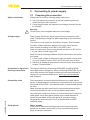
5 Connecting to power supply ................................................................................................. 21
5.1 Preparing the connection ............................................................................................... 21
5.2 Connecting ..................................................................................................................... 22
5.3 Wiring plan, single chamber housing.............................................................................. 23
5.4 Wiring plan, double chamber housing ............................................................................ 24
5.5 Wiring plan, Ex-d-ia double chamber housing ................................................................ 26
5.6 Double chamber housing with VEGADIS-Adapter .......................................................... 27
5.7 Wiring plan - version IP 66/IP 68, 1 bar ........................................................................... 28
5.8 Supplementary electronics ............................................................................................. 28
5.9 Switch-on phase............................................................................................................. 28
6 Set up with the display and adjustment module ................................................................ 29
6.1 Insert display and adjustment module ............................................................................ 29
6.2 Adjustment system ......................................................................................................... 30
6.3 Parameter adjustment - Quick setup .............................................................................. 31
6.4 Parameter adjustment - Extended adjustment................................................................ 32
6.5 Saving the parameterisation data ................................................................................... 50
7 Setup with PACTware ............................................................................................................. 51
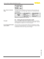
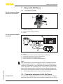
7.1 Connect the PC .............................................................................................................. 51
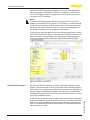
7.2 Parameter adjustment with PACTware ............................................................................ 51
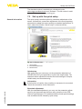
7.3 Set up with the quick setup ............................................................................................. 53
7.4 Saving the parameterisation data ................................................................................... 54
8 Set up with other systems .................................................................................................... 55
8.1 DD adjustment programs ............................................................................................... 55
8.2 Field Communicator 375, 475 ........................................................................................ 55

3
Contents
VEGAFLEX 83 • Two-wire 4 … 20 mA/HART
41834-EN-190131
9 Diagnostics and servicing .................................................................................................... 56
9.1 Maintenance .................................................................................................................. 56
9.2 Diagnosis memory ......................................................................................................... 56
9.3 Status messages ............................................................................................................ 57
9.4 Rectify faults ................................................................................................................... 60
9.5 Exchanging the electronics module ................................................................................ 63
9.6 Software update ............................................................................................................. 64
9.7 How to proceed if a repair is necessary .......................................................................... 64
10 Dismount................................................................................................................................. 65
10.1 Dismounting steps.......................................................................................................... 65
10.2 Disposal ......................................................................................................................... 65
11 Supplement ............................................................................................................................ 66
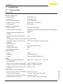
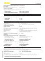
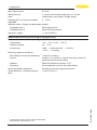
11.1 Technical data ................................................................................................................ 66
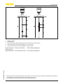
11.2 Dimensions .................................................................................................................... 76
11.3 Industrial property rights ................................................................................................. 82
11.4 Trademark ...................................................................................................................... 82
Safety instructions for Ex areas
TakenoteoftheExspecicsafetyinstructionsforExapplications.
These instructions are attached as documents to each instrument
with Ex approval and are part of the operating instructions.
Editing status: 2018-11-05

4
1 About this document
VEGAFLEX 83 • Two-wire 4 … 20 mA/HART
41834-EN-190131
1 About this document
1.1 Function
This operating instructions provides all the information you need for
mounting, connection and setup as well as important instructions for
maintenance,faultrectication,theexchangeofpartsandthesafety
of the user. Please read this information before putting the instrument
into operation and keep this manual accessible in the immediate
vicinity of the device.
1.2 Target group
This operating instructions manual is directed to trained personnel.
Thecontentsofthismanualmustbemadeavailabletothequalied
personnel and implemented.
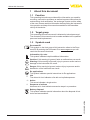
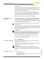
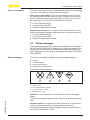
1.3 Symbols used
Document ID
This symbol on the front page of this instruction refers to the Docu-
ment ID. By entering the Document ID on www.vega.com you will
reach the document download.
Information, tip, note
This symbol indicates helpful additional information.
Caution: If this warning is ignored, faults or malfunctions can result.
Warning: If this warning is ignored, injury to persons and/or serious
damage to the instrument can result.
Danger: If this warning is ignored, serious injury to persons and/or
destruction of the instrument can result.
Ex applications
This symbol indicates special instructions for Ex applications.
•
List
The dot set in front indicates a list with no implied sequence.
→
Action
This arrow indicates a single action.
1 Sequence of actions
Numbers set in front indicate successive steps in a procedure.
Battery disposal
This symbol indicates special information about the disposal of bat-
teries and accumulators.

5
2 For your safety
VEGAFLEX 83 • Two-wire 4 … 20 mA/HART
41834-EN-190131
2 For your safety
2.1 Authorised personnel
All operations described in this documentation must be carried out
onlybytrained,qualiedpersonnelauthorisedbytheplantoperator.
During work on and with the device, the required personal protective
equipment must always be worn.
2.2 Appropriate use
VEGAFLEX 83 is a sensor for continuous level measurement.
Youcannddetailedinformationabouttheareaofapplicationin
chapter "Product description".
Operational reliability is ensured only if the instrument is properly
usedaccordingtothespecicationsintheoperatinginstructions
manual as well as possible supplementary instructions.
2.3 Warning about incorrect use
Inappropriate or incorrect use of this product can give rise to applica-
tion-specichazards,e.g.vesseloverllthroughincorrectmounting
or adjustment. Damage to property and persons or environmental
contamination can result. Also, the protective characteristics of the
instrument can be impaired.
2.4 General safety instructions
This is a state-of-the-art instrument complying with all prevailing
regulations and directives. The instrument must only be operated in a
technicallyawlessandreliablecondition.Theoperatorisresponsi-
ble for the trouble-free operation of the instrument. When measuring
aggressive or corrosive media that can cause a dangerous situation
if the instrument malfunctions, the operator has to implement suitable
measures to make sure the instrument is functioning properly.
During the entire duration of use, the user is obliged to determine the
compliance of the necessary occupational safety measures with the
current valid rules and regulations and also take note of new regula-
tions.
The safety instructions in this operating instructions manual, the na-
tional installation standards as well as the valid safety regulations and
accident prevention rules must be observed by the user.
For safety and warranty reasons, any invasive work on the device
beyond that described in the operating instructions manual may be
carried out only by personnel authorised by the manufacturer. Arbi-
traryconversionsormodicationsareexplicitlyforbidden.Forsafety
reasons,onlytheaccessoryspeciedbythemanufacturermustbe
used.
To avoid any danger, the safety approval markings and safety tips on
the device must also be observed and their meaning read in this oper-
ating instructions manual.

6
2 For your safety
VEGAFLEX 83 • Two-wire 4 … 20 mA/HART
41834-EN-190131
2.5 EU conformity
ThedevicefullsthelegalrequirementsoftheapplicableEUdirec-
tives.ByaxingtheCEmarking,weconrmtheconformityofthe
instrument with these directives.
YoucanndtheEUconformitydeclarationonourwebsiteunder
www.vega.com/downloads.
Electromagnetic compatibility
Instruments in four-wire or Ex-d-ia version are designed for use in an
industrial environment. Nevertheless, electromagnetic interference
from electrical conductors and radiated emissions must be taken into
account, as is usual with class A instruments according to EN 61326-
1.Iftheinstrumentisusedinadierentenvironment,theelectromag-
netic compatibility to other instruments must be ensured by suitable
measures.
2.6 NAMUR recommendations
NAMUR is the automation technology user association in the process
industry in Germany. The published NAMUR recommendations are
acceptedasthestandardineldinstrumentation.
ThedevicefullstherequirementsofthefollowingNAMURrecom-
mendations:
•
NE 21 – Electromagnetic compatibility of equipment
•
NE 43 – Signal level for fault information from measuring transduc-
ers
•
NE53–Compatibilityofelddevicesanddisplay/adjustment
components
•
NE107–Self-monitoringanddiagnosisofelddevices
For further information see www.namur.de.
2.7 Installation and operation in the USA and
Canada
This information is only valid for USA and Canada. Hence the follow-
ing text is only available in the English language.
Installations in the US shall comply with the relevant requirements of
the National Electrical Code (ANSI/NFPA 70).
Installations in Canada shall comply with the relevant requirements of
the Canadian Electrical Code
A Class 2 power supply unit has to be used for the installation in the
USA and Canada.
2.8 Environmental instructions
Protection of the environment is one of our most important duties.
That is why we have introduced an environment management system
with the goal of continuously improving company environmental pro-
tection.Theenvironmentmanagementsystemiscertiedaccording
to DIN EN ISO 14001.

7
2 For your safety
VEGAFLEX 83 • Two-wire 4 … 20 mA/HART
41834-EN-190131
Pleasehelpusfullthisobligationbyobservingtheenvironmental
instructions in this manual:
•
Chapter "Packaging, transport and storage"
•
Chapter "Disposal"

8
3 Product description
VEGAFLEX 83 • Two-wire 4 … 20 mA/HART
41834-EN-190131
3 Product description
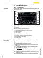
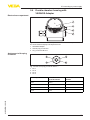
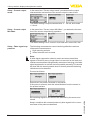
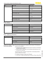
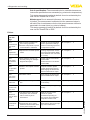
3.1 Conguration
Thetypelabelcontainsthemostimportantdataforidenticationand
use of the instrument:
2
1
12
13
14
15
11
10
5
3
6
4
7
8
9
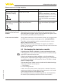
Fig. 1: Layout of the type label (example)
1 Instrument type
2 Product code
3 Approvals
4 Power supply and signal output, electronics
5 Protection rating
6 Probe length (measurement accuracy optional)
7 Process and ambient temperature, process pressure
8 Material wetted parts
9 Order number
10 Serial number of the instrument
11 Symbol of the device protection class
12 ID numbers, instrument documentation
13 Reminder to observe the instrument documentation
14 NotiedauthorityforCEmarking
15 Approval directives
The type label contains the serial number of the instrument. With it
youcanndthefollowinginstrumentdataonourhomepage:
•
Product code (HTML)
•
Delivery date (HTML)
•
Order-specicinstrumentfeatures(HTML)
•
Operating instructions and quick setup guide at the time of ship-
ment (PDF)
•
Order-specicsensordataforanelectronicsexchange(XML)
•
Testcerticate(PDF)-optional
Go to "www.vega.com", "Search". Enter the serial number.
Alternatively, you can access the data via your smartphone:
•
Download the VEGA Tools app from the "Apple App Store" or the
"Google Play Store"
•
Scan the Data Matrix code on the type label of the instrument or
Type label
Serial number - Instru-
ment search

9
3 Product description
VEGAFLEX 83 • Two-wire 4 … 20 mA/HART
41834-EN-190131
•
Enter the serial number manually in the app
This operating instructions manual applies to the following instrument
versions:
•
Hardware from 1.0.0
•
Software from 1.3.0
•
OnlyforinstrumentversionswithoutSILqualication
The instrument and the electronics version can be determined via the
product code on the type label as well as on the electronics.
•
Standard electronics: Type FX80H.-
The scope of delivery encompasses:
•
Sensor
•
Optional accessory
•
Optionally integrated Bluetooth module
•
Documentation
– Quick setup guide VEGAFLEX 83
– Instructions for optional instrument features
– Ex-specic"Safety instructions" (with Ex versions)
– Ifnecessary,furthercerticates
Information:
In this operating instructions manual, the optional instrument features
are described. The respective scope of delivery results from the order
specication.
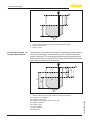
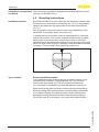
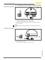
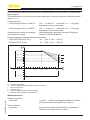
3.2 Principle of operation
The VEGAFLEX 83 is a level sensor with coated cable or rod probe
for continuous level or interface measurement, particularly suitable for
applications in the chemical industry.
High frequency microwave pulses are guided along a steel cable or
a rod. Upon reaching the product surface, the microwave pulses are
reected.Therunningtimeisevaluatedbytheinstrumentandoutput
as level.
Scope of this operating
instructions
Versions
Scope of deliver
y
Application area
Functional principle -
level measurement

10
3 Product description
VEGAFLEX 83 • Two-wire 4 … 20 mA/HART
41834-EN-190131
d
h
1
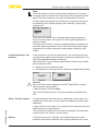
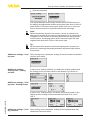
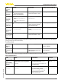
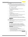
Fig. 2: Level measurement
1 Sensorreferenceplane(sealsurfaceoftheprocesstting)
d Distance to the level
h Height - Level
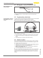
High frequency microwave impulses are guided along a steel cable or
rod. Upon reaching the product surface, a part of the microwave im-
pulsesisreected.Theotherpartpassesthroughtheupperproduct
andisreectedbytheinterface.Therunningtimestothetwoproduct
layers are processed by the instrument.
TS
d1
h1
h2
d2
1
L2
L1
L3
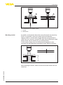
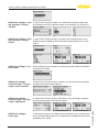
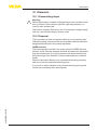
Fig. 3: Interface measurement
1 Sensorreferenceplane(sealsurfaceoftheprocesstting)
d1 Distance to the interface
d2 Distance to the level
TS Thickness of the upper medium (d1 - d2)
h1 Height - Interface
h2 Height - Level
L1 Lower medium
L2 Upper medium
L3 Gas phase
Functional principle - in-
terface measurement

11
3 Product description
VEGAFLEX 83 • Two-wire 4 … 20 mA/HART
41834-EN-190131
Upper medium (L2)
•
The upper medium must not be conductive
•
The dielectric constant of the upper medium or the actual distance
to the interface must be known (input required). Min. dielectric con-
stant:1.6.Youcanndalistofdielectricconstantsonourhome
page: www.vega.com.
•
The composition of the upper medium must be stable, no varying
products or mixtures
•
Theuppermediummustbehomogeneous,nostratications
within the medium
•
Min. thickness of the upper medium 50 mm (1.97 in)
•
Clear separation from the lower medium, emulsion phase or detri-
tus layer max. 50 mm (1.97 in)
•
If possible, no foam on the surface
Lower medium (L1)
•
The dielectric constant must be 10 higher than the dielectric
constant of the upper medium, preferably electrically conductive.
Example: upper medium dielectric constant 2, lower medium at
least dielectric constant 12.
Gas phase (L3)
•
Air or gas mixture
•
Gas phase - dependent on the application, gas phase does not
always exist (d2 = 0)
The instrument is always preset to the application "Level measure-
ment".
For the interface measurement, you can select the requested output
signal with the setup.
3.3 Packaging, transport and storage
Your instrument was protected by packaging during transport. Its
capacity to handle normal loads during transport is assured by a test
based on ISO 4180.
The packaging of standard instruments consists of environment-
friendly, recyclable cardboard. For special versions, PE foam or PE
foil is also used. Dispose of the packaging material via specialised
recycling companies.
Transport must be carried out in due consideration of the notes on the
transport packaging. Nonobservance of these instructions can cause
damage to the device.
The delivery must be checked for completeness and possible transit
damage immediately at receipt. Ascertained transit damage or con-
cealed defects must be appropriately dealt with.
Up to the time of installation, the packages must be left closed and
stored according to the orientation and storage markings on the
outside.
Prerequisites for inter-
face measurement
Output signal
P
ackaging
Transport
Transport inspection
Storage

12
3 Product description
VEGAFLEX 83 • Two-wire 4 … 20 mA/HART
41834-EN-190131
Unless otherwise indicated, the packages must be stored only under
the following conditions:
•
Not in the open
•
Dry and dust free
•
Not exposed to corrosive media
•
Protected against solar radiation
•
Avoiding mechanical shock and vibration
•
Storage and transport temperature see chapter "Supplement -
Technical data - Ambient conditions"
•
Relative humidity 20 … 85 %
With instrument weights of more than 18 kg (39.68 lbs) suitable and
approved equipment must be used for lifting and carrying.
3.4 Accessories and replacement parts
The display and adjustment module PLICSCOM is used for measured
value indication, adjustment and diagnosis. It can be inserted into the
sensor or the external display and adjustment unit and removed at
any time.
The integrated Bluetooth module (optional) enables wireless adjust-
ment via standard adjustment devices:
•
Smartphone/tablet (iOS or Android operating system)
•
PC/notebook with Bluetooth USB adapter (Windows operating
system)
Youcanndfurtherinformationintheoperatinginstructions"Display
andadjustmentmodulePLICSCOM" (Document-ID 36433).
The interface adapter VEGACONNECT enables the connection of
communication-capable instruments to the USB interface of a PC. For
parameter adjustment of these instruments, the adjustment software
PACTware with VEGA-DTM is required.
Youcanndfurtherinformationintheoperatinginstructions"Interface
adapterVEGACONNECT" (Document-ID 32628).
The VEGADIS 81 is an external display and adjustment unit for VEGA
plics
®
sensors.
For sensors with double chamber housing the interface adapter
"
VEGADISadapter" is also required for VEGADIS 81.
Youcanndfurtherinformationintheoperatinginstructions
"VEGADIS81" (Document-ID 43814).
The VEGADIS adapter is an accessory part for sensors with double
chamber housings. It enables the connection of VEGADIS 81 to the
sensor housing via an M12 x 1 plug.
Youcanndfurtherinformationinthesupplementaryinstructions
"VEGADISadapter" (Document-ID 45250).
Storage and transport
temperature
Lifting and carr
ying
PLICSCOM
VEGACONNECT
VEGADIS 81
VEGADIS adapter

13
3 Product description
VEGAFLEX 83 • Two-wire 4 … 20 mA/HART
41834-EN-190131
VEGADIS 82 is suitable for measured value indication and adjustment
of sensors with HART protocol. It is looped into the 4 … 20 mA/HART
signal cable.
Youcanndfurtherinformationintheoperatinginstructions
"VEGADIS824…20mA/HART" (Document-ID 45300).
PLICSMOBILE T81 is an external GSM/GPRS/UMTS radio unit for
transmission of measured values and for remote parameter adjust-
ment of HART sensors. The adjustment is carried out via a PC with
PACTware and the corresponding DTM or via smartphone/tablet with
the VEGA Tools app. The connection is made via the Bluetooth inter-
face integrated in PLICSMOBILE.
Youcanndfurtherinformationintheoperatinginstructions
"PLICSMOBILET81/B81/S81" (Document-ID 55234).
PLICSMOBILE 81 is an internal GSM/GPRS/UMTS radio unit for
HART sensors for transmission of measured values and for remote
parameter adjustment. The adjustment is carried out via a PC with
PACTware and the corresponding DTM or via smartphone/tablet with
the VEGA Tools app. The connection is made via the Bluetooth inter-
face integrated in PLICSMOBILE.
Youcanndfurtherinformationinthesupplementaryinstructions
"PLICSMOBILE" (Document-ID 56160).
The protective cover protects the sensor housing against soiling and
intense heat from solar radiation.
Youwillndadditionalinformationinthesupplementaryinstructions
manual "Protective cover" (Document-ID 34296).
Screwedangesareavailableindierentversionsaccordingtothe
following standards: DIN 2501, EN 1092-1, BS 10, ASME B 16.5,
JIS B 2210-1984, GOST 12821-80.
Youcanndadditionalinformationinthesupplementaryinstructions
manual "FlangesaccordingtoDIN-EN-ASME-JIS".
The electronics module VEGAFLEX series 80 is a replacement part
forTDRsensorsofVEGAFLEXseries80.Thereisadierentversion
available for each type of signal output.
Youcanndfurtherinformationintheoperatinginstructionsmanual
"ElectronicsmoduleVEGAFLEXseries80".
The display and adjustment module can be optionally replaced by a
display and adjustment module with heating function.
You can use this display and adjustment module in an ambient tem-
perature range of -40 … +70 °C.
Youcanndfurtherinformationintheoperatinginstructions"Display
and adjustment module with heating" (Document-ID 31708).
If the standard sensor housing is too big or in case of strong vibra-
tions, an external housing can be used.
VEGADIS 82
PLICSMOBILE T81
PLICSMOBILE 81
Protectiv
e cover
Flanges
Electronics module
Display and adjustment
module with heating
External housing

14
3 Product description
VEGAFLEX 83 • Two-wire 4 … 20 mA/HART
41834-EN-190131
Then the sensor housing is made of stainless steel. The electronics is
located in the external housing which can be mounted in a distance of
up to 10 m (147 ft) to the sensor by using a connection cable.
Youcanndadditionalinformationintheoperatinginstructions
manual "Externalhousing" (Document-ID 46802).
If you mount the VEGAFLEX 83 in a bypass tube or standpipe, you
have to avoid contact to the bypass tube by using a spacer at the
probe end.
Youcanndadditionalinformationintheoperatinginstructions
manual "Centering".
Centering

15
4 Mounting
VEGAFLEX 83 • Two-wire 4 … 20 mA/HART
41834-EN-190131
4 Mounting
4.1 General instructions
Protect your instrument against moisture ingress through the following
measures:
•
Use a suitable connection cable (see chapter "Connectingto
power supply")
•
Tighten the cable gland or plug connector
•
Whenmountinghorizontally,turnthehousingsothatthecable
gland or plug connector point downward
•
Lead the connection cable downward in front of the cable entry or
plug connector.
This applies mainly to outdoor installations, in areas where high
humidity is expected (e.g. through cleaning processes) and on cooled
or heated vessels.
To maintain the housing protection, make sure that the housing lid is
closed during operation and locked, if necessary.
Makesurethatthedegreeofcontaminationspeciedinchapter
"Technical data" meets the existing ambient conditions.
Metric threads
In the case of instrument housings with metric thread, the cable
glands are screwed in at the factory. They are sealed with plastic
plugs as transport protection.
You have to remove these plugs before electrical connection.
NPT thread
In the case of instrument housings with self-sealing NPT threads, it is
not possible to have the cable entries screwed in at the factory. The
free openings for the cable glands are therefore covered with red dust
protection caps as transport protection. The dust protection caps do
notprovidesucientprotectionagainstmoisture.
Prior to setup you have to replace these protective caps with ap-
proved cable glands or close the openings with suitable blind plugs.
Make sure before mounting that all parts of the instrument exposed to
the process are suitable for the existing process conditions.
These are mainly:
•
Active measuring component
•
Processtting
•
Process seal
Process conditions in particular are:
•
Process pressure
•
Process temperature
•
Chemical properties of the medium
•
Abrasionandmechanicalinuences
Youcannddetailedinformationontheprocessconditionsinchapter
"Technical data" as well as on the type label.
Protection against mois-
ture
Cable glands
Suitability f
or the process
conditions

16
4 Mounting
VEGAFLEX 83 • Two-wire 4 … 20 mA/HART
41834-EN-190131
The instrument is suitable for standard and extended ambient condi-
tions acc. to IEC/EN 61010-1.
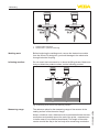
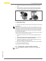
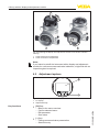
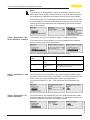
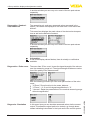
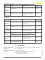
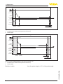
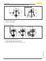
4.2 Mounting instructions
Mount VEGAFLEX 83 in such a way that the distance to vessel instal-
lations or to the vessel wall is at least 300 mm (12 in). In non-metallic
vessels, the distance to the vessel wall should be at least 500 mm
(19.7 in).
During operation, the probe must not touch any installations or the
vessel wall. If necessary, fasten the probe end.
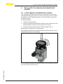
In vessels with conical bottom it can be advantageous to mount the
sensor in the center of the vessel, as measurement is then possible
nearly down to the lowest point of the bottom. Keep in mind that
measurement all the way down to the tip of the probe may not be pos-
sible. The exact value of the min. distance (lower dead band) is stated
in chapter "Technical data" of the operating instructions.
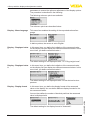
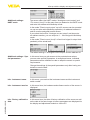
Fig. 4: Vessel with conical bottom
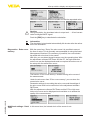
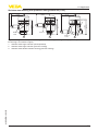
Plastic vessel/Glass vessel
The guided microwave principle requires a metallic surface on the
processtting.Therefore,inplasticvessels,etc.,useaninstru-
mentversionwithange(fromDN50)orplaceametalsheet
(ø>200mm/8in)beneaththeprocessttingwhenscrewingitin.
Makesurethattheplatehasdirectcontactwiththeprocesstting.
When mounting rod or cable probes in vessels without metal walls,
e.g.inplasticvessels,themeasuredvaluecanbeinuencedby
strongelectromagneticelds(emittedinterferenceaccordingto
EN 61326: class A). In this case, use a probe with coaxial version.
Suitability for the ambient
conditions
Installation position
Type of vessel

17
4 Mounting
VEGAFLEX 83 • Two-wire 4 … 20 mA/HART
41834-EN-190131
1 2
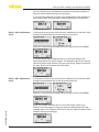
Fig. 5: Mounting in non-metallic vessel
1 Flange
2 Metal sheet
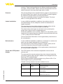
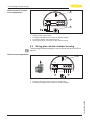
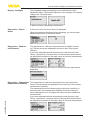
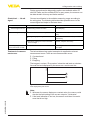
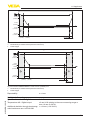
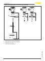
Ifpossible,avoidsockets.Mountthesensorushwiththevesseltop.
If this is not possible, use short sockets with small diameter.
Higher sockets or sockets with a bigger diameter can generally be
used. They can, however, increase the upper blocking distance (dead
band). Check if this is relevant for your measurement.
In such cases, always carry out a false signal suppression after
mounting.Youcanndfurtherinformationunder"Setup procedure".
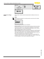
h
d
dh
DN25 ... DN150
≤ 150 mm (
5.91")
≤ 100 mm (3.94")> DN150 ... DN200
Fig. 6: Mounting socket
Whenweldingthesocket,makesurethatthesocketisushwiththe
vessel top.
Mounting socket

18
4 Mounting
VEGAFLEX 83 • Two-wire 4 … 20 mA/HART
41834-EN-190131
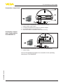
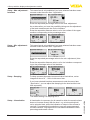
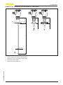
1 2
Fig.7:Socketmustbeinstalledush
1 Unfavourable mounting
2 Socketush-optimummounting
Before beginning the welding work, remove the electronics module
from the sensor. By doing this, you avoid damage to the electronics
through inductive coupling.
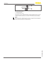
Donotmounttheinstrumentsinorabovethellingstream.Makesure
thatyoudetecttheproductsurface,nottheinowingproduct.
Fig.8:Mountingofthesensorwithinowingmedium
The reference plane for the measuring range of the sensors is the
sealingsurfaceofthethreadorange.
Keep in mind that a min. distance must be maintained below the refer-
ence plane and possibly also at the end of the probe - measurement
in these areas is not possible (dead band). The length of the cable
can be used all the way to the end only when measuring conductive
Welding work
Inowingmedium
Measuring range

19
4 Mounting
VEGAFLEX 83 • Two-wire 4 … 20 mA/HART
41834-EN-190131
products.Theseblockingdistancesfordierentmediumsarelisted
in chapter "Technical data". Keep in mind for the adjustment that the
default setting for the measuring range refers to water.
Theprocessttingmustbesealedifthereisgaugeorlowpressurein
the vessel. Before use, check if the seal material is resistant against
the measured product and the process temperature.
Themax.permissiblepressureisspeciedinchapter"Technical
data" or on the type label of the sensor.
Incaseofdicultinstallationconditions,theprobecanalsobe
mounted laterally. For this, adapt the rod with rod extensions or
angled segments.
To compensate for the resulting changes in signal runtime, let the
instrument determine the probe length automatically.
The determined probe length can deviate from the actual probe
length when using curved or angled segments.
If internal installations such as struts, ladders, etc. are present on the
vessel wall, the measuring probe should be mounted at least 300 mm
(11.81 in) away from the vessel wall.
Youcanndfurtherinformationinthesupplementaryinstructionsof
the rod extension.
Incaseofdicultinstallationconditions,forexampleinasocket,the
probe can be suitably adapted with a rod extension.
To compensate for the resulting changes in signal runtime, let the
instrument determine the probe length automatically.
Youcanndfurtherinformationinthesupplementaryinstructionsof
the rod and cable components.
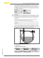
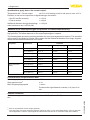
The PTFE washer of the antenna encapsulation serves also as
process seal.
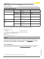
To compensate the normal prestress loss due to the seal materials,
youhavetousealsodiscspringsinadditiontotheangescrewsfor
fasteningPTFEplatedanges.
Werecommendexibleretainingwashers(e.g.SchnorrVSorS)or
detent edged rings (e.g. Gross VS KD).
Suitable retaining elements are also available from us.
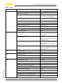
Size Article no. Type
M16,
7
/
8
" 32880 Detent edged ring
Gross VS KD
M20,
3
/
4
" 32881 Detent edged ring
Gross VS KD
M24,
5
/
8
" 32882 Retaining washer
Schnorr VS, Schnorr S
Pressure
Lateral installation
Rod extension
Torque with PTFE plated
anges

20
4 Mounting
VEGAFLEX 83 • Two-wire 4 … 20 mA/HART
41834-EN-190131
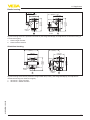
1
2
Fig. 9: Use of disc springs
1 Single disc spring
2 Laminated disc spring
TheangescrewsofVEGAFLEX83mustbetightenedwithatorque
of approx. 60 Nm (44 lbf ft) so that the PTFE washer seals reliably.
Note:
We recommend, retightening the screws in regular intervals depend-
ing on process pressure and temperature
Page is loading ...
Page is loading ...
Page is loading ...
Page is loading ...
Page is loading ...
Page is loading ...
Page is loading ...
Page is loading ...
Page is loading ...
Page is loading ...
Page is loading ...
Page is loading ...
Page is loading ...
Page is loading ...
Page is loading ...
Page is loading ...
Page is loading ...
Page is loading ...
Page is loading ...
Page is loading ...
Page is loading ...
Page is loading ...
Page is loading ...
Page is loading ...
Page is loading ...
Page is loading ...
Page is loading ...
Page is loading ...
Page is loading ...
Page is loading ...
Page is loading ...
Page is loading ...
Page is loading ...
Page is loading ...
Page is loading ...
Page is loading ...
Page is loading ...
Page is loading ...
Page is loading ...
Page is loading ...
Page is loading ...
Page is loading ...
Page is loading ...
Page is loading ...
Page is loading ...
Page is loading ...
Page is loading ...
Page is loading ...
Page is loading ...
Page is loading ...
Page is loading ...
Page is loading ...
Page is loading ...
Page is loading ...
Page is loading ...
Page is loading ...
Page is loading ...
Page is loading ...
Page is loading ...
Page is loading ...
Page is loading ...
Page is loading ...
Page is loading ...
Page is loading ...
Page is loading ...
Page is loading ...
Page is loading ...
Page is loading ...
-
 1
1
-
 2
2
-
 3
3
-
 4
4
-
 5
5
-
 6
6
-
 7
7
-
 8
8
-
 9
9
-
 10
10
-
 11
11
-
 12
12
-
 13
13
-
 14
14
-
 15
15
-
 16
16
-
 17
17
-
 18
18
-
 19
19
-
 20
20
-
 21
21
-
 22
22
-
 23
23
-
 24
24
-
 25
25
-
 26
26
-
 27
27
-
 28
28
-
 29
29
-
 30
30
-
 31
31
-
 32
32
-
 33
33
-
 34
34
-
 35
35
-
 36
36
-
 37
37
-
 38
38
-
 39
39
-
 40
40
-
 41
41
-
 42
42
-
 43
43
-
 44
44
-
 45
45
-
 46
46
-
 47
47
-
 48
48
-
 49
49
-
 50
50
-
 51
51
-
 52
52
-
 53
53
-
 54
54
-
 55
55
-
 56
56
-
 57
57
-
 58
58
-
 59
59
-
 60
60
-
 61
61
-
 62
62
-
 63
63
-
 64
64
-
 65
65
-
 66
66
-
 67
67
-
 68
68
-
 69
69
-
 70
70
-
 71
71
-
 72
72
-
 73
73
-
 74
74
-
 75
75
-
 76
76
-
 77
77
-
 78
78
-
 79
79
-
 80
80
-
 81
81
-
 82
82
-
 83
83
-
 84
84
-
 85
85
-
 86
86
-
 87
87
-
 88
88


Vega VEGAFLEX 83 Operating instructions
- Category
- Measuring, testing & control
- Type
- Operating instructions
Ask a question and I''ll find the answer in the document
Finding information in a document is now easier with AI
Related papers
-
 Vega VEGAFLEX 86 Operating instructions
-
 Vega VEGAFLEX 81 Operating instructions
-
Vega VEGAFLEX 82 Operating instructions
-
Vega VEGAFLEX 83 Operating instructions
-
 Vega VEGADIS 82 Operating instructions
-
 Vega VEGADIS 82 Operating instructions
-
 Vega VEGADIS 82 Operating instructions
-
 Vega VEGAFLEX 81 Operating instructions
-
Vega PLICSMOBILE Series Operating instructions
-
Vega PLICSCOM Operating instructions


Other documents
-
 Barclay Products 4110-66-CP Installation guide
-
 BINMASTER NCR-80 Quick Setup Manual
-
Tecfluid SERIES LU Instructions Manual
-
 IFM Electronic efector 160 Operating instructions
-
Pepperl+Fuchs LTC57 Operating instructions
-
IFM RMU200 Operating instructions
-
Omega LVRD10 Series Owner's manual
-
Pepperl+Fuchs LTC51 Operating instructions
-
ITT Controls RMG DRY TEST METERS Owner's manual
-
CEM Mars 6 Owner's manual


