
34/0
34/0
#ALL5S&IRST
$/./42%452.4/34/2%
&ORIMMEDIATEHELPWITHASSEMBLYORPRODUCTINFORMATION
CALLOURTOLLFREENUMBER
OREMAIL
CUSTOMERSERVICE BACKYARDPRODUCTSLLCCOM
/URSTAFFISREADYTOPROVIDEASSISTANCE
!PRILTHROUGH/CTOBER-&!-TO0-%34
3ATURDAY!-TO0-%34
.OVEMBERTHROUGH-ARCH-&!-TO0-%34

4HISPAGEINTENTIONALLYLEFTBLANK

04/21/2011
KEEP THIS MANUAL FOR FUTURE REFERENCE
ACTUAL FLOOR SIZE IS 96 x 144" (244 x 366 cm)
16767
BEFORE YOU BEGIN
IMPORTANT!
READ INSTRUCTIONS THOROUGHLY PRIOR TO BEGINNING ASSEMBLY.
- CUSTOMER SERVICE -
Call: 1-800-221-1849 email: customerservice@backyardproductsllc.com
• BUILDING RESTRICTIONS AND APPROVALS
Be sure to check with local building department and homeowners association for speci c restrictions and/ or requirements before building
.
• ENGINEERED DRAWINGS
Contact our Customer Service Team if engineered drawings are needed to pull local permits.
• SURFACE PREPARATION
To ensure proper assembly you must build your shed on a level surface. Recommended methods and materials to level your shed are
listed on page 8.
• CHECK ALL PARTS
Inventory all parts listed on pages 4 - 6. Contact our Customer Service Team if any parts are missing or damaged.
• ADDITIONAL MATERIALS
You will need additional materials to complete your shed. See page 3 for required and optional materials and quantities.
MAJESTIC 8' x 12' (244 x 366 cm)
MARCO SERIES
ASSEMBLY MANUAL
A Backyard Products Company

2
TOOLS
Safety! Always use approved safety glasses during assembly.
OptionalRequired
HELPFUL REMINDER SYMBOLS
Look for these symbols for helpful reminders throughout this manual.
ORIENT LUMBER AND TRIM FOR BEST APPEARANCE
= Assistance Required; two or more people.
= Ensure squareness.
= Important required step or operation.
= Helpful assembly hint.
= Mark part with pencil.
= Beginning of steps for assembly or installation.
= You have nished the assembly or installation.
= Level
❑ Gloves
Framing lumber is graded for structural strength and not appearance. Exterior trim is graded for one good side.
Always install the material leaving the best edge and best surface visible. Please remember that these blemishes in no way
negatively affect the strength or integrity of our product. (See Fig. A, B, C.)
A
❑ Safety Glasses
❑ Tape Measure
❑ Paint Tools
❑ Ladder
❑ Caulk Gun
❑ Hammer
❑ Level
FINISH
BEGIN
❑ Pencil
❑ Phillips
Screwdriver
❑ Drill / Driver
❑ 1/4" Drill Bit
❑ 3/8" Drill Bit
❑ 1/2" Drill Bit
❑ #2 Philips Drive Bit
❑ Tool Belt/
Nail Pouch
❑ Chalk Line
❑ Nail Gun
• gun nails
❑ Tin Snips
(for drip edge)
❑ Square
or
❑ Utility Knife
❑ Shingle Blades
B C

3
COMPLETING YOUR SHED
You will need these additional materials:
OPTIONAL MATERIALS
FOUNDATION OR FLOOR MATERIALS
ADDITIONAL MATERIALS
DRIP EDGE ..................... 50 Feet #15 ROOFING FELT
To cover 122 Sq. Ft. of roof area.
1" GALVANIZED ROOFING NAILS.........1/4 Lb
For roo ng felt.
REFER TO THE BACK OF THIS MANUAL AND THE MANUFACTURER’S INSTRUCTIONS
FOR INSTALLATION OF SHINGLES, DRIP EDGE AND FELT.
3-TAB SHINGLES ............................ 5 Bundles
PAINT FOR SIDING .......................... 2 Gallons
Use 100% acrylic latex exterior paint. (2) coats recommended.
CAULK ................................................. 3 Tubes
Use acrylic latex exterior caulk that is paintable.
1" GALVANIZED ROOFING NAILS.... 3 Lbs
For shingles.
PAINT FOR TRIM .............................1 Quart
Use 100% acrylic latex exterior paint.
WOOD GLUE ....................... Exterior Rated
REINFORCED WOOD FLOOR FRAME (OPTIONAL)
IMPORTANT! The included oor has been designed for general use. Depending on your speci c use you may want to construct a
heavy duty oor frame by adding additional oor joists (shown below as shaded). Below is a list of additional materials (not included):
x6
x24
2 x 4 x 8' (5 x 10 x 244 cm) Treated Lumber
Cut to (6) 2 x 4 x 93" (5 x 10 x 236 cm)
ea. 3" (7,6 cm) Hot Dipped Galvanized Nails
Optional 12" (30,5 cm) spacing
Standard 24" (61 cm) spacing
• This shed kit includes a complete wood oor frame system. It does not include any oor panels.
• See page 7 for the additional Á oor panel sizes and quantities required.
• This shed kit does not include ANY leveling materials.
• See the FLOOR LEVELING section on page 8 for recommended methods and suggested materials to properly level your
Á oor, as this will vary depending on your speciÀ c site.

WOOD SIZE CONVERSION CHART
Nominal Board Size Actual Size
1" x 4".................3/4" x 3-1/2" (1,9 x 8,9 cm)
2" x 4"..............1-1/2" x 3-1/2" (3,8 x 8,9 cm)
2" x 3"..............1-1/2" x 2-1/2" (3,8 x 6,3 cm)
1" x 3".................3/4" x 2-1/2" (3,8 x 6,3 cm)
PARTS IDENTIFICATION AND SIZES
RS
RS
Part identi cation
letters are stamped on some parts.
Check these locations for
part stamp.
Treated lumber is stamped:
All treated lumber
is stamped:
WALLS
x1
2 x 3 x 31" (5 x 7,6 x 79 cm)
AQ
x14
2 x 3 x 78-1/2" (5 x 7,6 x 199 cm)
FU
x2
2 x 3 x 82-1/2" (5 x 7,6 x 210 cm)
FV
x2
2 x 3 x 91" (5 x 7,6 x 231 cm)
PS
x1
2 x 3 x 84" (5 x 7,6 x 213 cm)
FW
x4
2 x 3 x 96" (5 x 7,6 x 244 cm)
PT
x2
2 x 4 x 96" (5 x 10 x 244 cm)
TP
x2
2 x 3 x 13" (5 x 7,6 x 33 cm)
RK
x4
2 x 3 x 48" (5 x 7,6 x 122 cm)
NK
x1
2 x 3 x 23" (5 x 7,6 x 58 cm)
FR
x1
2 x 4 x 64" (5 x 10 x 162,5 cm)
UX
x1
1 x 3 x 12" (2,5 x 7,6 x 30,5 cm)
DI
x2
2 x 3 x 35-1/4 " (5 x 7,6 x 89,5 cm)
FS
PARTS LIST
INVENTORY YOUR PARTS before you begin.
We suggest sorting parts by the category they are listed in.
RAFTERS
x3
JF
1 x 4 x 60" (2,5 x 10 x 152 cm)
x10
6 x 23-1/4" (15 x 59 cm)
TRIM
ZJ
x2
5/8 x 2-1/2 x 72" (1,6 x 6,3 x 183 cm)
AW
x2
2 x 3 x 41-7/8" (5 x 7,6 x 106 cm)
x10
3/8 x 1-3/4 x 82-1/4" (0,9 x 4,4 x 209 cm)
x2
2 x 4 x 48-3/4" (5 x 10 x 124 cm)
AN
x3
5/8 x 2-1/2 x 9" (1,6 x 6,3 x 23 cm)
EY
AG
x4
2 x 4 x 59-1/8" (5 x 10 x 150 cm)
x10
2 x 4 x 55-3/16" (5 x 10 x 140 cm)
AA
3/4" (1,9 cm)
x1
1 x 3 x 5" (2,5 x 7,6 x 12,7 cm)
GAUGE BLOCK FOR 3/4" (1,9 CM) MEASUREMENT.
GAA
x4
2 x 2 x 84" (5 x 5 x 213 cm)
METAL CORNER TRIM
x1
2 x 3 x 9" (5 x 7,6 x 23 cm)
NA
4
FLOOR
x7
2 x 4 x 93" (5 x 10 x 236 cm)
x2
2 x 4 x 48" (5 x 10 x 122 cm)
x2
2 x 4 x 96" (5 x 10 x 244 cm)

SHELFDOOR
OO
x2
2 x 3 x 69" (5 x 7,6 x 175,3 cm)
PARTS LIST continued...
x1
2 x 3 x 28-5/8" (5 x 7,6 x 73 cm)
FQ
x5
2 x 3 x 96" (5 x 7,6 x 244 cm)
PT
x2
2 x 4 x 96" (5 x 10 x 244 cm)
TP
5
PANEL PARTS LIST
ROOF PANELSSHELF PANELSWINDOW
NOTE: Panel parts are not stamped.
Shelf panels are
7/16" (1,1 cm) thick.
Roof panels are
7/16" (1,1 cm) thick.
7/16 x 23-7/8 x 91"
(1,1 x 61 x 231 cm)
7/16 x 44-1/4 x 48"
(1,1 x 112 x 122 cm)
x1
7/16 x 25-3/4 x 48"
(1,1 x 65,4 x 122 cm)
x4
x2
7/16 x 11-1/4 x 25-3/4"
(1,1 x 29 x 65,4 cm)
x4
7/16 x 11-1/4 x 96"
(1,1 x 29 x 244 cm)
x2
7/16 x 11-7/8 x 96"
(1,1 x 30 x 244 cm)
x2
7/16 x 48 x 96"
(1,1 x 122 x 244 cm)
x2
x2
10-1/2 x 32-1/2"
(27 x 82,5 cm)

x6
3/8 x 48 x 84"
(1 x 122 x 213 cm)
WALL PANEL & DOORS PARTS LIST
x1 x1 x1 x1
x2x2
x1
LEFT DOOR
x1
RIGHT DOOR
x3
BOXES
x4
BOXES
x110
113
x70
x96
x64
x20
x48
NAIL BOXES (Shown Actual Size)
DOOR HARDWARE (Not Actual Size)
FASTENER/HARDWARE BAG (Shown Actual Size)
6
1-1/4" (3,2 cm)
1-1/4" (3,2 cm)
2" (5,0 cm)
3" (7,6 cm)
3/4" (1,9 cm)
2" (5,0 cm)
3" (7,6 cm)
2" (5,0 cm)
1-1/2" (3,8 cm)
x1
x2
x2
1" (2,5 cm)
1-1/4" (3,2 cm)
x2
x6
3/4" (1,9 cm)

7
FLOOR PANELS (Not Included)
You will need oor panels and nails to complete your oor. Floor panel sizes and
quantities are shown below.
NOTE: Use a minimum of 5/8" (1,6 cm) oriented strand board (OSB).
x1
1 lb. of 2" (5,0 cm) Hot Dipped Galvanized Box-Type Nails
2" (5,0 cm)
NOTES
x3
5/8 x 48 x 96"
(1,6 x 122 x 244 cm)

8
D
O
OR
FLOOR LEVELING OPTIONS
There are multiple ways to level your oor frame. Our recommended leveling method is shown below.
Leveling materials are not included in this kit.
PREFERRED METHOD - 4x4 TREATED RUNNERS
Measurements to
centers of 4x4's.
• 3" Screws angled into 4x4.
• (2) at each point frame
• and 4x4 touch.
12"
(30,5 cm)
12"
(30,5 cm)
• Level under 4x4 runners only.
• Locate leveling material 12" from ends of runners and no more than 48" apart.
• Asphalt shingles should be used between 4x4 runners and blocks or treated lumber. Never use
shingles in direct contact with ground.
• For best results and aiding in water drainage use gravel under each concrete block.
LEVELING METHODS
• If you are building your shed on a concrete foundation see the following page.
CONCRETE
MATERIAL REQUIRED
x2
4" x 4" x 12' (10 x 10 x 366 cm)Treated Lumber
Fasteners for Frame to 4"x 4".
(3" Screws shown as one option.) Minimum (28) 3" screws / exterior grade.
Use only wood treated for ground contact and fasteners approved for use with treated wood.
Always support frame seams.
Leveling higher than 16" not recommended.
LEVELING MATERIALS
Gravel
2x4 Treated Lumber
Solid Masonry Blocks in 1", 2", 4" or 8" thickness
Asphalt Shingles
8" Block
4" Block
Gravel
Gravel
Do not exceed 16".
4x4 Runner
Shingle
Shingle
Maximum between leveling
material locations.
48"
12"
2x4 Treated Lumber
2" Block
Level
12"

9
CONCRETE FOUNDATION
Your kit contains all materials to construct a wooden oor. If you choose to install your kit
on a concrete slab refer to the diagram below.
A
B
C
4"
(10 cm)
3-1/2"
(8,9 cm)
DOOR
• A treated 2 x 4" (5 x 10 cm) sill plate is required when installing your shed on concrete. Hint: Use treated lumber in your kit or
purchase full length treated lumber.
• Use a high quality exterior grade caulk beneath all sill plates.
• Fasten 2 x 4" (5 x 10 cm) sill plates to slab using approved concrete anchors (fasteners not included).
• Check local code for concrete foundation requirements.
NOTES
Treated Sill Plate
Caulk between sill plate
and concrete.
Allow new concrete slabs to cure for at least seven (7) days.
2" x 4" x 12' (5 x 10 x 366 cm)
2" x 4" x 8' (5 x 10 x 244 cm)
Caulk
Requires:
x2
x2
x1
MUST be treated lumber.
MUST be treated lumber.
96" (244 cm)96" x 144" (244 x 366 cm) 137" (345 cm)8'x 12' (244 x 366 cm) 144" (366 cm)
AActual Size B CBuilding Size

10
93"
(236 cm)
96"
(244 cm)
144"
(366 cm)
120"
(305 cm)
96"
(244 cm)
96"
(244 cm)
72"
(183 cm)
48"
(122 cm)
24"
(61 cm
48"
(122 cm)
96"
(244 cm)
Offset
Seam
Offset
Seam
DOOR
3" (7,6 cm) x32
x2
x7
2 x 4 x 96" (5 x 10 x 244 cm)
2 x 4 x 93" (5 x 10 x 236 cm)
x2
2 x 4 x 48" (5 x 10 x 122 cm)
PARTS REQUIRED:
Center
on marks
FLOOR FRAME
Flush
Flush
Look for
Stamp
TREATED
HINT:
For easier nailing
stand on frame.
2
1
Use two 3" nails at each mark.
Orient parts as shown on at surface. Measure and mark.
BEGIN
You have nished your oor frame. Proceed to level and square frame.
FINISH
3

11
DOOR
FINISH
5
LEVEL AND SQUARE FLOOR FRAME
Before attaching oor decking, it is important to level and square the oor frame.
A level and square oor frame is required to correctly construct your shed.
BEGIN
2
3
4
1
Use level and check the frame is level before applying oor panels.
Check for frame squareness by measuring diagonally across corners. If the measurements are the
same, the frame is square. The diagonal measurement will be approximately 173-1/16" (440 cm).
When the frame is level and square secure one side of frame to the 4x4 runners using one fastener at
ends of each runner. Move to the opposite end of the frame. Secure the frame to 4x4 runners with one
fastener at ends of each runner making sure the frame remains square
(Fig. A).
Once the oor frame is level and square fasten the frame to the 4x4 runners at each point the frame
contacts the 4x4 runners.
See page 8 for the preferred oor leveling method.
First, secure
at ends with
one fastener.
Second, secure
at ends with
one fastener.
173-1/16"
(440 cm)
173-1/16"
(440 cm)
Fig. A

12
FLOOR PANELS NOT INCLUDED. SEE
PAGE 7 FOR PANEL SIZES
AND QUANTITIES.
48"
(122 cm)
144"
(366 cm)
6"
(15 cm)
DOOR
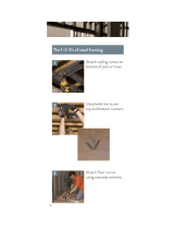
Move to the opposite side. Using the long edge of the panel as a lever, move the
panel side-to-side until the top corner is ush to the oor frame (Fig. B).
Secure panel with two 2" nails in the corners.
2
BEGIN
1
3
4
Continue attaching the panel using 2" nails 6" apart on edges and 12" apart inside panel.
Use a chalk line or use pre-painted grid lines to nail into joists under panel.
Ensure your Á oor frame is square by installing one panel
and squaring frame.
Fig. A
Fig. B
Fig. C
Check the oor frame is square by measuring diagonally across the frame corners. If the measurements are the
same your oor frame is square. The measurement will be approximately 173-1/16" (440 cm) (Fig. C).
PARTS REQUIRED:
x1
5/8 x 48 x 96"
(1,6 x 122 x 244 cm)
Grid lines up
12" (30 cm)
2" (5 cm) x55
Flush
Flush
Flush
(2) Nails
(2) Nails
FLOOR PANELS
3/4"
(1,9 cm)
173-1/16"
(440 cm
173-1/16"
(440 cm
Attach the 48 x 96" panel with the rough side up (painted-grid lines side) with the 48"
edge and corner ush to the oor frame (Fig A). Secure panel with two 2" nails in the
corners.

13
48"
(122 cm)
48"
(122 cm)
144"
(366 cm)
6"
(15 cm)
12"
(30) cm
DOOR
PARTS REQUIRED:
FINISH
7
You have nished attaching your oor panels.
Continue installing panels with rough side up
(painted grid lines).
Use grid lines on panel for 2" nails 6" apart on
edges, and 12" apart inside panels.
5
7
6
x2
5/8 x 48 x 96"
(1,6 x 122 x 244 cm)
Grid lines
up
2" (5 cm) x110
FLOOR PANELS
Flush
FlushFlush

14
DOOR
DOOR
Back wall
Front wall
Side wall
Side Wall
Check the Á oor frame is level after installing Á oor panels.
Re-level if needed.
HINT:
IMPORTANT!
• The Á oor should used as a stable work surface for wall construction.
• Organize your assembly procedure during the build process
to avoid over-handling of the walls.

SIDE WALL FRAMES
PARTS REQUIRED:
144”
(366 cm)
120”
(305 cm)
96”
(244 cm)
96”
(244 cm)
72”
(183 cm)
48”
(122 cm)
48”
(122 cm)
48”
(122 cm)
24”
(61 cm)
78-1/2”
(199 cm)
FU x7
NK
PT
PT
NK
x14
2 x 3 x 78-1/2" (5 x 7,6 x 199 cm)
FU
x4
2 x 3 x 96" (5 x 7,6 x 244 cm)
PT
x4
2 x 3 x 48" (5 x 7,6 x 122 cm)
NK
HINT:
For easier nailing
stand on frame.
15
3" (7,6 cm) x64
DOOR
BEGIN
1
Use two 3" nails at each mark.
IMPORTANT! You will build two walls the same.
Orient parts on edge on oor. Measure and mark.
2
TOENAILING
Offset Seam
Offset Seam

16
SIDE WALL PANELS
48 x 84"
122 x 213 cm)
PARTS REQUIRED:
x1
2" (5 cm) x45
Fig. B
Fig. A
1-1/2"
(3,8 cm)
1-1/2"
(3,8 cm)
3/4"
(1,9 cm)
3/4"
(1,9 cm)
2 Nails
2 Nails
2 x 3 x 13" (5 x 7,6 x 33 cm) as SPACER
x1
RK
DOOR
Place the 48 x 84" panel onto wall frame with primed side up as shown.
Use the gauge block to mark the 3/4" measurement on the wall stud.
Use RK as a 1-1/2" gauge block at top. Secure panel with two 2" nails in
the corners (Fig. A).
Nail the panel using 2" nails 6" apart on edges and 12" apart inside panel.
Ensure your wall frame is square by installing one panel and
squaring frame.
Move to the opposite end. Using the long edge of the panel as a lever
move the panel side-to-side until you have a 3/4" measurement on the
wall stud. Secure corner with two 2" nails (Fig. B).
4
5
3
3/4" GAUGE
BLOCK
48"
(122 cm)
3/4"
(1,9 cm)
1-1/2"
(3,8 cm)
3/4"
(1,9 cm)
12"
(30) cm
6"
(15 cm)
3/4"
GAUGE
BLOCK
For squareness, maintain 3/4" and
1-1/2" measurement along panel edges.
BEGIN HERE
HINT: Use RK
as 1-1/2" gauge
Primed side up
GAA

17
1-1/2"
(3,8 cm)
3/4"
(19 mm)
48"
(122 cm)
12"
(30 cm)
6"
(15 cm)
Flush
1-1/2"
(3,8 cm)
48"
(122 cm)
12"
(30 cm)
6"
(15 cm)
Flush
For squareness maintain
Á ush and 1-1/2" measurement
along panel edges.
For squareness maintain Á ush and
1-1/2" measurement along panel edges.
HINT:
Use RK as
1-1/2" gauge
HINT:
Use RK as
1-1/2" gauge
Place center 48" panel on frame as
shown with primed side facing up.
Nail using 2" nails 6" apart on edges
and 12" apart inside panel.
6
Place end 48" panel on frame as shown
with primed side facing up.
Nail using 2" nails 6" apart on edges
and 12" apart inside panel.
7
You have nished building both your sidewalls.
FINISH
9
Primed
side up
Primed
side up
SIDE WALL PANELS
48 x 84"
122 x 213 cm)
PARTS REQUIRED:
x2
2" (5 cm) x90
2 x 3 x 13" (5 x 7,6 x 33 cm) as SPACER
x1
RK
DOO
R
8
Carefully ip the sidewall over.
Repeat STEPS 1-8 to assemble your
second side wall.
D
O
O
R
3/4" GAUGE
BLOCK
GAA

1-1/2" (3,8 cm) x11
Flush
36-1/4"
(92 cm)
1-1/4"
(3,2 cm)
1"
(2,5 cm)
36-1/4"
(92 cm)
2-1/2"
(6,3 cm)
2-1/2"
(6,3 cm)
18
BACK WALL
PARTS REQUIRED:
2 x 3 x 35-1/4" (5 x 7,6 x 89,5 cm)
2 x 3 x 91" (5 x 7,6 x 231 cm)
2 x 3 x 13" (5 x 7,6 x 33 cm)
x1
PS
x2
x1
FS
48 x 96"
(122 x 244 cm)
x1
DOOR
RK
3
2
4
Nail FS rst, 1" (2,5 cm) from panel bottom.
Use 1-1/2" nails only 6" (15 cm) apart.
Place
PS ush to FS. Hold the 36-1/4" (92 cm) measurement and nail with
1-1/2" nails 12" (30 cm) apart.
Place panel on
FS and PS with primed side up.
Orient parts on at on oor as shown.
PS
temporary support
PS
FS
Primed side
UP
Use only 1-1/2"
(3,8 cm) long nails
RK
temporary support
BEGIN
1
Page is loading ...
Page is loading ...
Page is loading ...
Page is loading ...
Page is loading ...
Page is loading ...
Page is loading ...
Page is loading ...
Page is loading ...
Page is loading ...
Page is loading ...
Page is loading ...
Page is loading ...
Page is loading ...
Page is loading ...
Page is loading ...
Page is loading ...
Page is loading ...
Page is loading ...
Page is loading ...
Page is loading ...
Page is loading ...
Page is loading ...
Page is loading ...
Page is loading ...
Page is loading ...
Page is loading ...
Page is loading ...
Page is loading ...
Page is loading ...
Page is loading ...
Page is loading ...
Page is loading ...
Page is loading ...
Page is loading ...
Page is loading ...
Page is loading ...
Page is loading ...
Page is loading ...
Page is loading ...
Page is loading ...
Page is loading ...
Page is loading ...
Page is loading ...
Page is loading ...
Page is loading ...
Page is loading ...
-
 1
1
-
 2
2
-
 3
3
-
 4
4
-
 5
5
-
 6
6
-
 7
7
-
 8
8
-
 9
9
-
 10
10
-
 11
11
-
 12
12
-
 13
13
-
 14
14
-
 15
15
-
 16
16
-
 17
17
-
 18
18
-
 19
19
-
 20
20
-
 21
21
-
 22
22
-
 23
23
-
 24
24
-
 25
25
-
 26
26
-
 27
27
-
 28
28
-
 29
29
-
 30
30
-
 31
31
-
 32
32
-
 33
33
-
 34
34
-
 35
35
-
 36
36
-
 37
37
-
 38
38
-
 39
39
-
 40
40
-
 41
41
-
 42
42
-
 43
43
-
 44
44
-
 45
45
-
 46
46
-
 47
47
-
 48
48
-
 49
49
-
 50
50
-
 51
51
-
 52
52
-
 53
53
-
 54
54
-
 55
55
-
 56
56
-
 57
57
-
 58
58
-
 59
59
-
 60
60
-
 61
61
-
 62
62
-
 63
63
-
 64
64
-
 65
65
-
 66
66
-
 67
67


Ask a question and I''ll find the answer in the document
Finding information in a document is now easier with AI
Related papers
-
Handy Home Products 18361-4 User guide
-
-
-
-
-
-
-
-
-
Other documents
-
Heartland 80644 Assembly Manual
-
Heartland Stratford 12’x8′ User manual
-
Unbranded PHS-SKIPPER User guide
-
 Dietrich Metal Framing 182131 Installation guide
-
-
-
-
Ekena Millwork PNL08X12AS-02 Installation guide
-
Martin VC-Grid 60 Template
-
Brookstone 437590 User Giude
