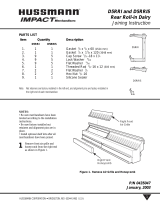
Hussmann IMPACT RL User manual

Type
User manual

This manual is also suitable for

Merchandisers
®
IIMMPPOORRTTAANNTT
Keep in store for
future reference!
Installation &
Operation Manual
Shipped With Case Data Sheets
P/N 0387183_D
Impact Series
October 2007
Reach-in Merchandisers
Medium and Low Temperature Cases
iii
P/N 0387183_D
Table of Contents
INSTALLATION
NSF Certification . . . . . . . . . . . . . . . . . . . . . . . . 1-1
Location . . . . . . . . . . . . . . . . . . . . . . . . . . . . . . . 1-1
Shipping Damage . . . . . . . . . . . . . . . . . . . . . . . . 1-1
Exterior Loading . . . . . . . . . . . . . . . . . . . . . . . . . 1-2
Merchandisers Shipped With End Installed . . . . 1-2
Shipping Braces . . . . . . . . . . . . . . . . . . . . . . . . . . 1-2
Remove Front Panel . . . . . . . . . . . . . . . . . . . . . . 1-2
Leveling . . . . . . . . . . . . . . . . . . . . . . . . . . . . . . . . 1-3
Door Adjustment . . . . . . . . . . . . . . . . . . . . . . . . . 1-4
Joining . . . . . . . . . . . . . . . . . . . . . . . . . . . . . . . . 1-4
Installing Splashguard Brackets . . . . . . . . . . . . . 1-4
Installing Bumpers . . . . . . . . . . . . . . . . . . . . . . . . 1-5
REFRIGERATION / ELECTRICAL
Refrigerant . . . . . . . . . . . . . . . . . . . . . . . . . . . . . . 2-1
Refrigerant Piping . . . . . . . . . . . . . . . . . . . . . . . . 2-1
Insulation . . . . . . . . . . . . . . . . . . . . . . . . . . . . . . . 2-1
Branch Line Piping . . . . . . . . . . . . . . . . . . . . . . . 2-2
Expansion Valve Adjustment . . . . . . . . . . . . . . . 2-3
Refrigeration Thermostat . . . . . . . . . . . . . . . . . . . 2-3
Defrost Termination Thermostat . . . . . . . . . . . . . 2-5
Control Settings . . . . . . . . . . . . . . . . . . . . . . . . . 2-6
Merchandiser Electrical Data . . . . . . . . . . . . . . . 2-8
Field Wiring . . . . . . . . . . . . . . . . . . . . . . . . . . . . 2-8
Electrical Connections . . . . . . . . . . . . . . . . . . . . 2-8
Identification of Wiring . . . . . . . . . . . . . . . . . . . 2-8
Wiring Color Code . . . . . . . . . . . . . . . . . . . . . . . 2-8
DRIP PIPING AND SPLASHGUARDS
Waste Outlet and Water Seal . . . . . . . . . . . . . . . . 3-1
Installing Drip Piping . . . . . . . . . . . . . . . . . . . . . 3-1
Installing Splashguards . . . . . . . . . . . . . . . . . . . . 3-2
Sealing Splashguard to Floor . . . . . . . . . . . . . . . 3-3
START UP / OPERATION
Start up . . . . . . . . . . . . . . . . . . . . . . . . . . . . . . . . . 4-1
Stocking . . . . . . . . . . . . . . . . . . . . . . . . . . . . . . . 4-1
Load Limits . . . . . . . . . . . . . . . . . . . . . . . . . . . . . 4-1
Load Limit Profiles . . . . . . . . . . . . . . . . . . . . . . . 4-1
Installing FDA/NSF Required Thermometer . . .4-2
MAINTENANCE
Care and Cleaning . . . . . . . . . . . . . . . . . . . . . . . . 5-1
Cleaning Honeycomb Assemblies . . . . . . . . . . . . 5-2
Cleaning Under Merchandisers . . . . . . . . . . . . . 5-2
Removing Scratches from Bumper . . . . . . . . . . . 5-2
SERVICE
Replacing Fan Motors and Blades . . . . . . . . . . . 6-1
Replacing Electric Defrost Heaters . . . . . . . . . . 6-3
Replacing Drain Pan Heater . . . . . . . . . . . . . . . . 6-5
RLT with Gas Defrost Only: Replacing
Slave Plate Heater . . . . . . . . . . . . . . . . . . . . . . 6-6
Removing RLT Return Air Bracket . . . . . . . . . . 6-7
Replacing Lamp Ballast (other than RLT) . . . . . 6-8
Replacing RLT Lamp Ballast . . . . . . . . . . . . . . . 6-9
Servicing Vertical Lighting . . . . . . . . . . . . . . . 6-10
Servicing Doors and Frames . . . . . . . . . . . . . . 6-10
Replacing Door or Door Frame Parts . . . . . . . 6-10
Replacing Damaged Drain Fitting . . . . . . . . . . . 6-11
Repairing Aluminum Coils . . . . . . . . . . . . . . . 6-12
WARRANTY
IMPORTANT
KEEP IN STORE FOR FUTURE REFERENCE
Quality that sets industry standards!
12999 St. Charles Rock Road • Bridgeton, MO 63044-2483
U.S. & Canada 1-800-922-1919 • Mexico 1-800-522-1900
www.hussmann.com
© 2007 Hussmann Corporation
®
®
INSTALLATION
TOOL LIST
Unloading From Trailer:
Lever Bar (also know as a Mule,
Johnson Bar, J-bar, Lever Dolly, and pry lever)
Moving Dolly
Setting Case Line-Up:
Level, 4 ft suggested
Ratchet
1
/
4 in. Socket
5
/16 in. Socket
1
/2 in. Socket
Battery Drill/Screw Gun
Caulking Gun
10 in. Adjustable Crescent Wrench
REVISION D — SEPTEMBER 2007
1. Added front panel text and illustration, Page 1-2.
2. Clarified shimming directions, page 1-3.
3. Added RLT information throughout.
4. Added note to remove bumper protective film, Page 1-6.
5. Added information on Always*Clear™ glass, page 5-1.
6. Removed reference to Anthony doors, Page 6-5.
7. Added repairing aluminum coil, Page 6-12.
8. Changed warranty page.
9. Added Installation Tool List, page iv.
10. Added revision history, page iv.
REVISION C — JUNE 2002
1. Added NSF information,pages 1-1,4-2 through 4-4.
2. Sections 2 through 6 are completely rewritten.
3. Changed warranty to March 15,2002.
P/N 0387183_D
iv CONTENTS
NSF CERTIFICATION
These merchandisers are manufactured to meet
ANSI / National Sanitation Foundation (NSF
®
)
Standard #7 requirements. Proper installation is
required to maintain certification. Near the serial
plate, each case carries a label identifying the
type of application for which the case was certi-
fied.
ANSI/NSF-7 Type I – Display Refrigerator / Freezer
Intended for 75°F / 55%RH Ambient Application
ANSI/NSF-7 Type II – Display Refrigerator / Freezer
Intended for 80°F / 55%RH Ambient Application
ANSI/NSF-7 – Display Refrigerator
Intended for Bulk Produce
LOCATION
These merchandisers are designed for displaying
products in air conditioned stores where tempera-
ture is maintained at or below the ANSI/NSF-7
specified level and relative humidity is maintained
at or below 55%.
Placing refrigerated merchandisers in direct sun-
light, near hot tables or near other heat sources
could impair their efficiency.
Like other merchandisers, these are sensitive to air
disturbances. Air currents passing around mer-
chandisers will seriously impair their operation.
Do NOT allow air conditioning, electric fans,
open doors or windows, etc. to create air currents
around the merchandisers.
To prevent sweating on the exterior surfaces
of merchandisers, there must be
A MINIMUM
CLEARANCE OF
4 INCHES (102 MM) between the
merchandisers and other fixtures or walls.
Product should always be maintained at proper
temperature. This means that from the time the
product is received, through storage, preparation
and display, the temperature of the product must
be controlled to maximize the life of the product.
SHIPPING DAMAGE
All equipment should be thoroughly examined
for shipping damage before and during unload-
ing.
This equipment has been carefully inspected at
our factory. Any claim for loss or damage must be
made to the carrier. The carrier will provide any
necessary inspection reports and/or claim forms.
Apparent Loss Or Damage
If there is an obvious loss or damage, it must be
noted on the freight bill or express receipt and
signed by the carrier’s agent; otherwise, carrier
may refuse claim. The carrier will supply neces-
sary forms.
Concealed Loss Or Damage
When loss or damage is not apparent until after
equipment is uncrated, a claim for concealed
damage is made. Upon discovering damage,
make request in writing to carrier for inspection
within 15 days and retain all packing. The carrier
will supply inspection report and required claim
forms.
Reach-In
P/N 0387183_D 1-1
HUSSMANN CORPORATION • BRIDGETON, MO 63044-2483 U.S.A.
INSTALLATION
Do not walk or put heavy objects on case.
CAUTION
!
EXTERIOR LOADING
Do NOT walk on top of merchandisers or dam-
age to the merchandisers and serious personal
injury could occur. T
HEY ARE NOT STRUCTURALLY
DESIGNED TO SUPPORT EXCESSIVE EXTERNAL
LOADING
such as the weight of a person. Do not
place heavy objects on the merchandiser.
MERCHANDISERS SHIPPED WITH END
INSTALLED
If the case was shipped with the end installed,
two long bolts were used to hold the shipping
brace to the end. If the shipping bolts are
reinserted after removing the brace, they will
extend into the product area and may damage
the coil. T
HEREFORE, BE SURE TO REPLACE
THESE BOLTS WITH THE SHORTER BOLTS
PROVIDED
.
Be careful not to damage the factory-installed
end while moving the merchandiser. Make sure
that tools are positioned past the end and beneath
the merchandiser’s support bar.
SHIPPING BRACES
Move the merchandiser as close as possible to its
permanent location and then remove all packag-
ing. Check for damage before discarding packag-
ing. Remove all separately packed accessories
such as kits and shelves.
Locate the shipping block in the
center of the heat exchanger (see
illustration), and remove it before
piping the merchandiser. This
block was installed to minimize
shipping vibration.
REMOVE FRONT PANEL
(D
OES NOT APPLY TO RLT)
Before setting case, remove the front panel as
follows: remove screws from front panel tabs,
then lift the front panel. Refer to the illustration
below. Set panel and screws aside to reinstall
once all electrical work is complete.
At completion of all electrical work, installation
contractor shall re-install the panels using care to
ensure all panels are centered and properly
fastened.
1-2 INSTALLATION
P/N 0387183_D WWW
.HUSSMANN.COM
Shipping
Block
Heat Exchanger
Top View of Merchandiser
Tabs Fit in
Retainer Slots
Edge Fits Over Raceway
Remove Screws
Front Panel
LEVELING
Merchandisers must be installed level
to ensure proper operation of the
refrigeration system and to ensure
proper drainage of defrost water.
When leveling merchandisers, use a
carpenter’s level as shown.
Metal leveling shims or wedges are
provided with each merchandiser for
use if needed.
NOTE: B
EGIN LINEUP LEVELING
FROM THE HIGHEST POINT OF THE
STORE FLOOR
.
Place shims under the rail and make
sure that they are positioned at a base
component (crossbar). This transfers
the weight directly from the loaded
case through to the floor. Placing shims
at other locations will cause uneven
distribution of weight leading to piping
leaks, as well as sagging or wracked
doors.
Reach-In
P/N 0387183_D 1-3
HUSSMANN CORPORATION • BRIDGETON, MO 63044-2483 U.S.A.
5-Door Island Shown
Bottom Front
Support
Skid/External Base
Electrical Wireway
Electrical Wireway
Shim
Here
NO SHIM
HERE
Base Component
Shim Here
Shim Here
Rear of Reach-in
Approximately
Centered
Base
Component
DOOR ADJUSTMENT
After leveling and joining the merchandisers,
adjust and level doors according to manufacturer’s
instructions shipped with each product. Factory
settings are lost due to vibration during shipment.
JOINING
Sectional construction means that two or more
merchandisers may be joined in line yielding one
long continuous display requiring only one pair
of ends. Joining kits and instructions are
shipped with each merchandiser.
To join like fixtures, a joining kit is required.
To join unlike fixtures, or like fixtures operating
at different temperatures, a 1
1
/
2 inch (38 mm)
partition kit is required. To join same
temperature fixtures on different defrost cycles,
a plexiglass partition kit is required.
A
LL JOINTS MUST BE AIR-TIGHT TO PREVENT
FORMATION OF ICE OR CONDENSATION
.
Refer to separate joining instruction shipped
with each case
INSTALLING SPLASHGUARD BRACKETS
1. Attach splashguard retainer and splashguard
retainer support to splashguard support brack-
et using two screws per bracket.
2. I
NSTALL SPLASHGUARD SUPPORT BRACKETS
BEFORE PIPING CASE. The leveling brackets
have a maximum extension of one (1) inch
(25 mm) for uneven floors.
DO NOT
PLACE SHIMS UNDER SPLASHGUARD
BRACKETS
.
1-4 INSTALLATION
P/N 0387183_D WWW
.HUSSMANN.COM
Splashguard Retainer
Splashguard
Retainer Support
Splashguard
Support Bracket
Screw
Base Rail
Screw
Bumper Retainer
INSTALLING BUMPERS
Offsetting the bumpers and top rails helps to
disguise the joint locations, giving the lineup a
smoother look.
Begin at the left end of the line-up. A starter
bumper is factory-installed with end kits. Insert
the internal joint trim, then add the full-length
bumper.
Align each bumper section with its retainer and
push into place, working from the end of the line-
up. Install full length bumpers and internal joint
trims offset across joints. Make sure that no gaps
exist between sections. Continue installing
bumpers the length of the line up.
Do NOT install the last bumper sections at this
time. These sections will be installed in the last
step.
Once all except the last section of bumper have
been installed, refrigerate the case line-up for
at least six (6) hours. The last sections of
bumper should be kept inside a refrigerated
case or cooler during this time to allow the
bumpers to contract.
Before installing the last full-length section,
measure the remaining space. Use a miter box
and fine-tooth saw to cut last bumper to length.
Install the last section.
Reach-In
P/N 0387183_D 1-5
HUSSMANN CORPORATION • BRIDGETON, MO 63044-2483 U.S.A.
Miter Box
Bumper
Merchandiser
Joint
Full Length
Bumpers
Starter
Bumper
Merchandiser
Joint
Internal Joint
Trims
Remove protective film from bumpers once
installation is complete.
Optional end bumpers are factory-installed.
1-6 INSTALLATION
P/N 0387183_D WWW
.HUSSMANN.COM
Reach-In
REFRIGERANT
The correct type of refrigerant will be stamped on
each merchandiser’s serial plate which is located
on the left-hand end of the interior top liner.
REFRIGERANT PIPING
Connection Location
The refrigerant line connections are at the right-
hand end of the merchandiser (as viewed from
the front) beneath the display pans.
After connections have been made, seal this out-
let thoroughly. Seal both the inside and the out-
side. We recommend using an expanding
polyurethane foam insulation.
Multiplexing
Piping of merchandisers operating on the same
refrigeration system may be run from merchan-
diser to merchandiser through the end frame
saddles provided for this purpose. D
O NOT
RUN
REFRIGERANT LINES THROUGH MERCHANDISERS
THAT ARE
NOT ON THE SAME REFRIGERATION
SYSTEM
as this may result in poor refrigeration
control and compressor failure.
NOTE: If Gas defrost is used, the liquid line
will need to be increased two sizes larger inside
the merchandiser area. This is necessary to ensure
even liquid drainage from all evaporators during
defrost.
Line Sizing
Refrigerant lines should be sized as shown on the
refrigeration legend that is furnished for the store
or according to ASHRAE guidelines.
Oil Traps
P-traps (oil traps) must be installed at the base of
all suction line vertical risers.
Pressure Drop
Pressure drop can rob the system of capacity. To
keep the pressure drop to a minimum, keep the
refrigerant line run as short as possible using a
minimum number of elbows. Where elbows are
required,
USE LONG RADIUS ELBOWS ONLY.
INSULATION
With GAS Defrost
The suction and liquid lines should NOT contact
each other and should be insulated separately
for a minimum of 30 ft (9144 mm) from the
merchandiser.
With OTHER Than Gas Defrost
The suction and liquid lines should be clamped or
taped together and insulated for a minimum of
30 ft (9144 mm) from the merchandiser.
With All Defrost
Additional insulation for the balance of the liquid
and suction lines is recommended wherever
condensation drippage is objectionable or the
lines are exposed to ambient conditions.
P/N 0387183_D 2-1
HUSSMANN CORPORATION • BRIDGETON, MO 63044-2483 U.S.A.
REFRIGERATION / ELECTRICAL
When brazing pipes be sure to use the
insulation blanket shipped with the
merchandiser to prevent damage to
the plastic case bottom.
CAUTION
!
Refrigeration lines are under pressure and
should be depressurized before attempting
to make any connections.
WARNING
!
BRANCH LINE PIPING
Suction Line – All Defrosts
Pitch in direction of flow.
May be reduced by one size at one third of case
run load and again after the second third. Do
NOT reduce below evaporator connection size.
Suction returns from evaporators enter at the
top of the branch line.
Liquid Line – Off-time and Electric Defrost
May be reduced by one size after one half the
case load run. Do not reduce below evaporator
connection size.
Take-offs to evaporators exit the bottom of the
liquid line. Provide an expansion loop for each
evaporator take-off (minimum 3 in. (76 mm)
diameter).
Liquid Line – Koolgas Defrost
Maximum of 6 evaporators per Branch System.
Increase the liquid line size inside the case by
two sizes over the branch size.
Branch Size In Case Size
1
/2
7
/8
5
/8 1
1
/8
7
/
8 1
3
/
8
1
1
/81
5
/8
1
3
/8 2
1
/8
Take-offs to evaporators exit the bottom of the
liquid line. Provide an expansion loop for each
evaporator take-off (minimum 3 in. (76 mm)
diameter).
2-2 REFRIGERATION / ELECTRICAL
P/N 0387183_D WWW
.HUSSMANN.COM
3-In. Loop (76 mm)
Suction Line Return
Liquid Line Take Off
From
Liquid
Manifold
To
Suction
Manifold
Electric or Offtime Defrost Liquid Line
Koolgas Defrost Liquid Line Two Sizes Larger in Merchandiser
The following information is applicable only
for piping Hussmann merchandisers to
Hussmann refrigeration equipment.
CAUTION
!
Reach-In
EXPANSION VALVE ADJUSTMENT
Expansion valves must be adjusted to fully feed
the evaporator. Before attempting to adjust
valves, make sure the evaporator is either clear or
only lightly covered with frost, and that the
merchandiser is within 10 deg F (6.5 deg C) of
its expected operating temperature. Adjust valves
as follows:
Attach two sensing probes
(either thermocouple or
thermistor) to the evaporator.
Position one under the clamp
holding the expansion valve
bulb; securely tape the other
to the coil inlet line.
Some “hunting
of the
expansion valve is normal.
The valve should be adjusted
so that during the hunting
THE GREATEST DIFFERENCE
BETWEEN THE TWO PROBES IS
3–5 deg F (1.7–2.8 deg C).
With this adjustment, during
a portion of the hunting the
temperature difference
between the probes will be
less than 3 deg F (1.7 deg C)
and at times 0.
Make adjustments of no more
than
1
/
4 turn for Balanced
Port TEV and
1
/
2 turn at a
time for other valve models.
Wait at least 15 minutes
before rechecking the probe
temperature or making further
adjustments.
REFRIGERATION THERMOSTAT
The thermostat body is located in the electrical
raceway near the right-hand end of the merchan-
diser. Its sensing bulb is located behind the right
end interior back panel.
P/N 0387183_D 2-3
HUSSMANN CORPORATION • BRIDGETON, MO 63044-2483 U.S.A.
Heat
Exchanger
body
Expansion
Valve
Expansion Valve
Bulb
Check Valve
Optional
Gas Bypass
Manifold
Thermostat
Component Location in
RL / RM / RLN / RLNI Models
2-4 REFRIGERATION / ELECTRICAL
P/N 0387183_D WWW
.HUSSMANN.COM
Component Location in RLT Models
RLT Coil
Heat Exchanger
Assembly
Check Valve
Distributor
Assembly
TEV Bulb
Mounted
on Side of
Suction Tube
TEV
Optional
Gas Bypass
DEFROST TERMINATION THERMOSTAT
The standard disc type defrost termination ther-
mostat is not adjustable.
On low-temperature merchandisers, the defrost
termination thermostat or optional termination
sensor is located on the right end of the coil at
the bottom center return bend. If an optional
adjustable thermostat is used, the bulb will be
clamped to the suction line on the left end of the
case.
ELECTRIC
ELECTRIC DEFROST ONLY
Defrost Termination
Thermostat Location
2 Door
RL
RLN
RLNI
RLNIE
3 Door
RL
RLN
RLNI
RLNIE
5 Door
&
4 Door
RL
RLN
RLNI
RLNIE
Reach-In
P/N 0387183_D 2-5
HUSSMANN CORPORATION • BRIDGETON, MO 63044-2483 U.S.A.
.
RLT
CONTROL SETTINGS
MEDIUM TEMPERATURE
Conventional Single Compressor
Measure Discharge Air Temperature
at the center of the case
at the discharge honeycomb.
Merchandiser temperature must be controlled by
a thermostat or other device with a 3–6 deg F
(1.7–3.3 deg C) differential. It will be wired to
control the compressor motor contactor.
Standard Off Time defrost is temperature termi-
nated. The defrost termination thermostats for all
the merchandisers on one compressor are wired
in series. On outdoor units the defrost timer will
control a liquid line solenoid beginning a defrost
pumpdown 4 minutes before defrost.
The defrost frequency and lengths listed may
require adjustment for specific store conditions.
Factors include:
Store temperature and humidity
Low head pressure
Long refrigerant line runs
Seasonal changes
Merchandiser temperature lower than
recommended
When practical, defrost when store is closed.
Low pressure control settings are applicable to
outdoor condensing units where ambient does not
fall below 0 deg F.
CONTROL SETTINGS
LOW TEMPERATURE
Conventional Single Compressor
Measure Discharge Air Temperature
at the center of the case
at the discharge honeycomb.
Merchandiser temperature must be controlled by
a thermostat or other device with a 3–6 deg F
(1.7–3.3 deg C) differential. It will be wired to
control the compressor motor contactor.
Standard Electric defrost is temperature terminat-
ed. The defrost termination thermostats for all
the merchandisers on one compressor are wired
in series. Failsafe must not control defrost cycle
length, especially when less than 208V power
supply is used for defrost heaters, or if frost
build up is heavy from shopping demands.
On outdoor units the defrost timer will control a
liquid line solenoid beginning a defrost pump-
down 4 minutes before defrost.
Optional Gas defrost is time terminated and has
fan cycling thermostat. The defrost frequency and
lengths listed may require adjustment for specific
store conditions. Factors include:
Store temperature and humidity
Low head pressure
Long refrigerant line runs
Seasonal changes
Merchandiser temperature lower than
recommended
When practical, defrost when store is closed.
Low pressure control settings are applicable to
outdoor condensing units where ambient does not
fall below 0 deg F.
2-6 REFRIGERATION / ELECTRICAL
P/N 0387183_D WWW
.HUSSMANN.COM
Reach-In
CONTROL SETTINGS
MEDIUM TEMPERATURE
Parallel Compressor Rack
Measure Discharge Air Temperature
at the center of the case
at the discharge honeycomb.
Merchandiser temperature must be controlled by
a mechanical or electronic pressure regulator or
thermostat that will be mounted on the rack.
Standard Off Time defrost is temperature termi-
nated. The defrost frequency and lengths listed
may require adjustment for specific store condi-
tions. Factors include:
Store temperature and humidity
Low head pressure
Long refrigerant line runs
Seasonal changes
Merchandiser temperature lower than
recommended
Stagger defrosts to maintain stable compressor
loading and sufficient defrost gas. When practi-
cal, defrost when store is closed.
CONTROL SETTINGS
LOW TEMPERATURE
Parallel Compressor Rack
Measure Discharge Air Temperature
at the center of the case
at the discharge honeycomb.
Merchandiser temperature must be controlled by
a mechanical or electronic pressure regulator or
thermostat that will be mounted on the rack.
Standard Electric defrost is temperature terminat-
ed. Failsafe must not control defrost cycle length,
especially when less than 208V power supply is
used for defrost heaters, or if frost build up is
heavy from shopping demands.
Optional Gas defrost is time terminated and has
fan cycling thermostat. The defrost frequency and
lengths listed may require adjustment for specific
store conditions. Factors include:
Store temperature and humidity
Low head pressure
Long refrigerant line runs
Seasonal changes
Merchandiser temperature lower
than recommended
Stagger defrosts to maintain stable compressor
loading and sufficient defrost gas. When practi-
cal, defrost when store is closed.
P/N 0387183_D 2-7
HUSSMANN CORPORATION • BRIDGETON, MO 63044-2483 U.S.A.
MERCHANDISER ELECTRICAL DATA
Merchandiser data sheets for specific models are
shipped with this manual. The data sheets provide
merchandiser electrical data, standard electrical
schematics, parts lists and performance data.
Refer to the merchandiser data sheets and case
serial plate for electrical information. Refer to
the separate wiring diagrams shipped with the
case for specific information about the case and
any optional wiring kits that may have been
applied.
FIELD WIRING
Field wiring must be sized for component amperes
stamped on the serial plate. Actual ampere draw
may be less than specified. Field wiring from the
refrigeration control panel to the merchandisers is
required for defrost termination thermostats and for
optional refrigeration thermostats. When multiple
merchandisers are on the same defrost circuit, the
defrost termination thermostats are wired in series.
ALWAYS CHECK THE SERIAL PLATE FOR
COMPONENT AMPERES
.
Electric Defrost is standard for low temperature
merchandisers and requires temperature termina-
tion. Gas defrost is optional
Off Time Defrost is standard for medium temper-
ature merchandisers and is time terminated.
When two or more merchandisers with full length
raceways are installed in line, remove the splash-
guards, end caps and raceway covers, and install
the nipple and nuts (supplied) providing electrical
passage from one merchandiser to the next.
Following NEC and local codes is the
responsibility of the electrical contractor.
ELECTRICAL CONNECTIONS
All wiring must be in compliance with NEC and
local codes. All electrical connections are to be
made to the terminal blocks in the electrical race-
way behind the lower front panel at the right-
hand end of the merchandiser (facing front).
IDENTIFICATION OF WIRING
Leads for all electrical circuits are identified by
colored plastic bands. These bands correspond to
the color code sticker (shown below) located
inside the merchandiser raceway.
2-8 REFRIGERATION / ELECTRICAL
P/N 0387183_D WWW
.HUSSMANN.COM
WIRING COLOR CODE
Leads for all electrical circuits are identified by a colored plastic band: neutral wire for each
circuit has either White insulation or a White plastic sleeve in addition to the color band.
P
INK ............REFRIG.THERMOSTAT LOW TEMP.ORANGE OR
LIGHT BLUE .REFRIG.THERMOSTAT NORM TEMP.TAN ..........LIGHTS
DARK BLUE..DEFROST TERM.THERMOSTAT MAROON ..RECEPTACLES
P
URPLE .......ANTI-SWEAT HEATERS YELLOW*..DEFROST HEATERS, 120V
B
ROWN ........FAN MOTORS RED*........DEFROST HEATERS, 208V
G
REEN* .......GROUND
*E
ITHER COLORED SLEEVE OR COLORED INSULATION
ELECTRICIAN NOTE: Use copper conductor wire only.
CASE MUST BE GROUNDED
Terminal block NOT for case-to-case wire
connection.
WARNING
!
WASTE OUTLET AND WATER SEAL
The waste outlet location varies for each of the 1,
2, 3, 4, and 5 door merchandisers. Drip piping is
located between the front case base and the
splashguard fixture and runs parallel to the case
(see Data Sheet for exact locations).
INSTALLING DRIP PIPING
Poorly or improperly installed drip pipes can
seriously interfere with the merchandiser's opera-
tion and result in costly maintenance and product
losses. Please follow the recommendations listed
below when installing drip pipes to ensure proper
installation.
1. Never use drip piping smaller than the nomi-
nal diameter of the pipe or water seal sup-
plied with the merchandiser.
2. When connecting drip piping, the water seal
must be used as part of the drip piping to pre-
vent air leakage or insect entrance. Never use
two water seals in series in any one drip pipe.
D
OUBLE WATER SEALS IN SERIES WILL CAUSE
AN AIR LOCK AND PREVENT DRAINING
.
3. Pitch the drip piping in the direction of flow.
There should be a minimum pitch of
1
/8 inch
per foot (1 mm per 100 mm).
4. Avoid long runs of drip piping. Long runs
make it impossible to provide the pitch neces-
sary for good drainage.
5. Provide a suitable air break between
flood rim of the floor drain and outlet
of drip pipe. To meet code on low base
merchandisers, it may be necessary
to install a field-supplied drip pipe
reducer. An alternative is to cut the
last section of drip pipe at an angle.
6. Prevent drip pipes from freezing:
A. Do NOT install drip pipes in contact with
uninsulated suction lines. Suction lines should
be insulated with a non-absorbent insulation
material.
B. Where drip pipes are located in dead air
spaces, such as between merchandisers or
between a merchandiser and a store wall,
provide means to prevent freezing.
Reach-In
P/N 0387183_D 3-1
HUSSMANN CORPORATION • BRIDGETON, MO 63044-2483 U.S.A.
DRIP PIPING AND SPLASHGUARDS
TEE-SIDE
Field Installed
Drip Piping
Field-Installed
Coupling
Field-Installed
Water Seal
Waste Outlet
Adapter
Tee
Fitting
Plug
Case Bottom
This End MUST Be
Above Tee Fitting
Splashguard
brackets
MUST be installed
before piping case.
(See Page 1-3)
CAUTION
!
INSTALLING SPLASHGUARDS
The splashguard is shipped inside each mer-
chandiser. AFTER merchandisers have been lev-
eled and joined, and all drip piping, electrical
and refrigeration work has been completed,
re-install the front color panel, then install the
splashguards.
First, position top of splashguard over the top
edge of the bracket; second, push the lower edge
of the splashguard toward the bottom of the
bracket until it snaps into place.
Splashguards are joined with a galvanized
metal splice connector that comes with the
joint kit. Join the splashguards before
installing on case.
3-2 DRIP PIPING AND SPLASHGUARDS
P/N 0387183_D WWW
.HUSSMANN.COM
1
2
Splashguard
Retaining
Bracket
Splashguard
Joint
Side
Detail
Splice Connector
Splashguard
  • Page 1 1
  • Page 2 2
  • Page 3 3
  • Page 4 4
  • Page 5 5
  • Page 6 6
  • Page 7 7
  • Page 8 8
  • Page 9 9
  • Page 10 10
  • Page 11 11
  • Page 12 12
  • Page 13 13
  • Page 14 14
  • Page 15 15
  • Page 16 16
  • Page 17 17
  • Page 18 18
  • Page 19 19
  • Page 20 20
  • Page 21 21
  • Page 22 22
  • Page 23 23
  • Page 24 24
  • Page 25 25
  • Page 26 26
  • Page 27 27
  • Page 28 28
  • Page 29 29
  • Page 30 30
  • Page 31 31
  • Page 32 32
  • Page 33 33
  • Page 34 34
  • Page 35 35
  • Page 36 36
  • Page 37 37
  • Page 38 38
  • Page 39 39
  • Page 40 40

Hussmann IMPACT RL User manual

Type
User manual
This manual is also suitable for

Ask a question and I''ll find the answer in the document

Finding information in a document is now easier with AI