Page is loading ...

LBI-38602A
EDACS
Μ−PΑ
UHF SYSTEM MODEL
PORTABLE FM RADIO
TABLE OF CONTENTS
REAR COVER ASSEMBLY . . . . . . . . . . LBI-38383
FRONT COVER ASSEMBLY (LATER)
LESS CONTROL BOARD . . . . . . . . . . . LBI-38834
CONTROL BOARD (LATER) . . . . . . . . . LBI-38828
UHF SERVICE SECTION . . . . . . . . . . . LBI-38604
Maintenance Manual
Mobile Communications

Copyright© April 1991, Ericsson GE Mobile Communications Inc.
The software contained in this device is copyrighted by Ericsson GE Mobile Communications, Inc. Unpublished rights
are reserved under the copyright laws of the United States.
TABLE OF CONTENTS
Page
SPECIFICATIONS . . . . . . . . . . . . . . . . . . . . . . . . . . . . . . . . . . . . . . . . . . . . . . . . . . 3
OPTIONS AND ACCESSORIES . . . . . . . . . . . . . . . . . . . . . . . . . . . . . . . . . . . . . . . . . . . 4
INTRODUCTION . . . . . . . . . . . . . . . . . . . . . . . . . . . . . . . . . . . . . . . . . . . . . . . . . . . 5
DESCRIPTION . . . . . . . . . . . . . . . . . . . . . . . . . . . . . . . . . . . . . . . . . . . . . . . . . . . . 6
Rear Cover Assembly . . . . . . . . . . . . . . . . . . . . . . . . . . . . . . . . . . . . . . . . . . . . . . 7
Front Cover Assembly . . . . . . . . . . . . . . . . . . . . . . . . . . . . . . . . . . . . . . . . . . . . . . 7
Antennas . . . . . . . . . . . . . . . . . . . . . . . . . . . . . . . . . . . . . . . . . . . . . . . . . . . . . 7
Batteries . . . . . . . . . . . . . . . . . . . . . . . . . . . . . . . . . . . . . . . . . . . . . . . . . . . . . 7
Rechargeable Battery Pack Disposal . . . . . . . . . . . . . . . . . . . . . . . . . . . . . . . . . . . . . . 8
Universal Device Connector . . . . . . . . . . . . . . . . . . . . . . . . . . . . . . . . . . . . . . . . . . . 8
PROGRAMMING . . . . . . . . . . . . . . . . . . . . . . . . . . . . . . . . . . . . . . . . . . . . . . . . . . 9
OPERATION . . . . . . . . . . . . . . . . . . . . . . . . . . . . . . . . . . . . . . . . . . . . . . . . . . . . . 9
Antenna/Radio/Battery Assembly . . . . . . . . . . . . . . . . . . . . . . . . . . . . . . . . . . . . . . . . 9
Alert Tones . . . . . . . . . . . . . . . . . . . . . . . . . . . . . . . . . . . . . . . . . . . . . . . . . . . . 9
Self-Test . . . . . . . . . . . . . . . . . . . . . . . . . . . . . . . . . . . . . . . . . . . . . . . . . . . . . 9
Trunked Operation . . . . . . . . . . . . . . . . . . . . . . . . . . . . . . . . . . . . . . . . . . . . . . . . 9
Conventional Operation . . . . . . . . . . . . . . . . . . . . . . . . . . . . . . . . . . . . . . . . . . . . . 10
Scan Operation - Trunked Mode . . . . . . . . . . . . . . . . . . . . . . . . . . . . . . . . . . . . . . . . 11
Scan Operation - Conventional Mode . . . . . . . . . . . . . . . . . . . . . . . . . . . . . . . . . . . . . . 11
Special Calls . . . . . . . . . . . . . . . . . . . . . . . . . . . . . . . . . . . . . . . . . . . . . . . . . . . 12
Operating Tips . . . . . . . . . . . . . . . . . . . . . . . . . . . . . . . . . . . . . . . . . . . . . . . . . . 13
INTRINSICALLY SAFE USAGE . . . . . . . . . . . . . . . . . . . . . . . . . . . . . . . . . . . . . . . . . . 14
MAINTENANCE . . . . . . . . . . . . . . . . . . . . . . . . . . . . . . . . . . . . . . . . . . . . . . . . . . . 14
Preventive Maintenance . . . . . . . . . . . . . . . . . . . . . . . . . . . . . . . . . . . . . . . . . . . . 14
ILLUSTRATIONS
Figure 1 - UDC Pin-Out . . . . . . . . . . . . . . . . . . . . . . . . . . . . . . . . . . . . . . . . . . . . 8
Figure 2 - Operating Controls . . . . . . . . . . . . . . . . . . . . . . . . . . . . . . . . . . . . . . . . . 12
Figure 3 - System Model Front Panel And Keypad Outline Diagram . . . . . . . . . . . . . . . . . . . . . 15
Figure 4 - Rear Cover Assembly Block Diagram . . . . . . . . . . . . . . . . . . . . . . . . . . . . . . . 16
Figure 5 - Front Cover Assembly Block Diagram . . . . . . . . . . . . . . . . . . . . . . . . . . . . . . . 17
NOTE
This manual is published by
Ericsson GE Mobile Communications Inc.
, without any warranty. Improvements and
changes to this manual necessitated by typographical errors, inaccuracies of current information, or improvements to pro-
grams and/or equipment, may be made by
Ericsson GE Mobile Communications Inc.
, at any time and without notice.
Such changes will be incorporated into new editions of this manual. No part of this manual may be reproduced or transmit-
ted in any form or by any means, electronic or mechanical, including photocopying and recording, for any purpose, without
the express written permission of
Ericsson GE
Mobile Communications, Inc.
LBI-38602
2

SPECIFICATIONS *
GENERAL
Frequency Bands 403 - 423 MHz
450 - 470 MHz
Oscillator Stability 2.5 ppm
Operating Temperature Range -30°C to + 60°C
Maximum Relative Humidity 90% at 55°C
Battery Voltage 7.5 Vdc (nominal)
Dimensions (H x W x D)
less battery, knobs and antenna 140 x 69 x 38 mm (5.52 x 2.72 x 1.50")
with Extra High Cap. Battery 232 x 69 x 40 mm (9.15 x 2.72 x 1.58")
Weight
less battery 540 grams (19 ounces)
with Extra High Cap. Battery 907 grams (32 ounces)
TRANSMITTER
Frequency Range 403 - 423 MHz
450 - 470 MHz
Maximum Frequency Separation 20 MHz (no degradation)
FM Deviation ±5 kHz
High/Low RF Power Output 5 Watts / 1 Watt (programmable on a per channel basis)
FM Hum and Noise -45dB (companion receiver)
Spurious and Harmonic Emissions -74 dBc
Audio Response + 1 to -3dB (6 dB/octave pre-emphasis from 300 to 3 kHz)
Audio Distortion less than 3% (at 1000 Hz tone, 3 kHz deviation)
RECEIVER
Frequency Range 403 - 423 MHz
450 - 470 MHz
Maximum Frequency Separation 20 MHz (no degradation)
Sensitivity (12 dB SINAD) -116 dBm (0.35 µV)
Adjacent Channel Selectivity (typical) -75 dB at 25 kHz
Critical Squelch 10 dB SINAD
Intermodulation (typical) -75 dB
Spurious and Image Rejection -75 dB
Audio Output (24 ohms load impedance) 500 mW (less than 5% distortion)
* These specifications are intended primarily for the use of the serviceman. See the appropriate Specifications Sheet for the
complete specifications.
LBI-38602
3

OPTIONS AND ACCESSORIES
Radios, Antennas, Batteries
Carrying Accessories
Audio Accessories
Chargers
LBI-38602
4

INTRODUCTION
The EDACS M-PA UHF System model radio is a
high quality microprocessor controlled synthesized port-
able FM radio. The unit complements the digitally
trunked system by providing a small, rugged, easy to op-
erate and easy to program portable radio for the UHF
trunking environment. The radio also provides conven-
tional communications in the UHF spectrum. The unit
meets or exceeds all APCO 16 portable radio equipment
requirements for digitally trunked and conventional
communications.
Trunked and conventional operation with the
EDACS M-PA radio is highlighted by its programming
versatility. Many features are PC programmable. This al-
lows tailored operation of the portable radio to meet the
needs of the radio system and the individual users.
The EDACS M-PA System model personality allows up
to 50 systems with 16 groups each, or 16 systems with 50
groups each, to be programmed and selected. Up to 48 con-
ventional channels can be stored in the radio. Ninety-nine
special calls can be stored. Special calls include individual
and telephone interconnect calls. DTMF operation is sup-
ported by the front panel 16-button keypad.
Radios operating in the trunk mode monitor a common
control channel from the site for channel assignments. This
designated control channel is the digital data link to/from
the radio and the site controller.
Working channels are allocated by the site via the con-
trol channel. Working channels carry the actual voice signal.
The allocated working channel may change several times
during a communication sequence. This change, if needed,
occurs at the start of a transmission sequence (at PTT time)
under the supervision of the site. Working channel access
time is typically 250 milliseconds and does not exceed 500
milliseconds as specified by the APCO 16 requirements.
When trunking operation is not wanted or is not possi-
ble, the unit can operate in the conventional mode. In the
conventional mode, the radio operates on 25 kHz allocated
channels.
TRUNKED FEATURES
Features which specifically apply to trunked mode
operation are listed below.
•
Programmable Multiple System Capability
-
Selection of up to 50 maximum systems (with 16
groups each) is capable. The radio can operate on
different trunked sites or on different systems on the
same site.
•
Programmable Multiple Group Capability
- The
radio can communicate with many groups within a
system. A maximum of 50 groups per system can be
assigned and selected.
The user pre-programs (via PC computer) the unit so
the Control Knob makes the group or group selection.
If the Control Knob is programmed for group selec-
tion, up to 16 groups can be selected; up to 50 sys-
tems can then be selected by the STEP button. If the
Control Knob is programmed for system selection, up
to 16 systems can be selected; up to 50 groups can
then be selected via the STEP button.
•
Programmable Group Call Capability
- The unit
can simultaneously call all units within a group.
•
Special Call Mode
- Trunked operation allows
communication via special (individual) calls. Up to
99 special calls can be pre-programmed into the
radio.
•
Remote Dynamic Regrouping Capability
- The
dispatch center can regroup radios for multi-agency
communications.
•
Remote Disable
- If lost or stolen, the unit may be
remotely disabled by the System Manager.
TRUNKED AND CONVENTIONAL
FEATURES
The M-PA System model radio has the following
features that apply to both trunked and conventional op-
eration. Up to 48 conventional channels can be pro-
grammed into the radio.
•
Rotary Control Knob
- The 16-position top-
mounted control allows easy selection of systems,
groups or conventional channels, according to how
the unit is programmed.
•
Volume Control Knob
- This rotatable control
provides quick and easy adjustments to the volume
level. Minimum volume levels can be programmed
into the unit. This feature prevents missed calls due to
a low volume setting.
•
Backlit Liquid Crystal Display
- The 8-digit
alphanumeric display provides programmable
customization and feedback to the operator of various
operating conditions. Icons (flags) located above and
below the digits alert the operator to various radio
conditions such as no control channel, conventional
mode enabled, transmitter in operation and a low
battery condition. Backlighting can be enabled or
disabled on a per channel or per group basis.
LBI-38602
5

• 16-Button Keypad - This front panel keypad allows
easy operator control of functions such as system or
group selection, scan operation, special call mode,
and manual dialing for telephone interconnect and/or
individual calls.
• Scan Operation - Trunked groups and conventional
channels can be scanned. Trunked groups which have
been previously added to the scan list (via the
operator) may be scanned. In conventional mode, the
radio may be configured for a fixed priority-one
channel, the selected channel as priority-one, a fixed
scan list, or a front keypad programmed scan list.
Dual-priority scan is supported in conventional mode.
• Telephone Interconnect - Special call mode allows
the operator to select and send pre-programmed
telephone calls. Telephone interconnect is performed
by the site. DTMF operation is supported by the front
panel keypad.
• Programmable via the Universal Device Connector
(UDC) - The entire operation of the radio can be
field customized by programming the unit using an
IBM PC or compatible computer. The programmed
personality is stored in a battery (internal lithium)
backed-up RAM.
• Simple Remote Control Capability - External
accessories can be connected to the UDC such as a
headset, a speaker-mic or a lanyard. Connection of
the speaker-mic allows the operator to remotely
control PTT operation and audio level of the external
speaker. An antenna jack is located on the UDC for
the connection of a remote mounted antenna such as
when the radio is used in a vehicular charger or
repeater.
• Emergency Signalling Feature - Pressing a single
recessed button instantly sends an alert message on a
pre-programmed channel. The radio ID number is
transmitted and the unit is given top priority in the
system. Emergency signalling can also be enabled by
a lanyard connected to the UDC.
• Programmable Carrier Control Timer - A
programmable transmit time will automatically
disable the transmitter and provide an alerting tone
after time-out. This feature prevents radio damage and
unnecessary channel traffic in the event of a "stuck"
mic. CCT is reset on every PTT and the alert tone is
removed upon release of the PTT button.
• Programmable Transmitter Power Levels -
Transmitter power level (high or low) is PC
programmable into the radio such that it is
automatically selected channel-by-channel.
• Automatic Squelch - Squelch operation in the
trunked mode is automatically controlled. In
conventional operation, squelch threshold can be
programmed on a per channel basis. Squelch circuits
are designed so that annoying squelch pops, which
may occur at the end of a received message, are
minimized.
• Programmable Multi-Tone Channel Guard
(CTCSS) - Channel Guard tone frequencies within
the range of 67 Hz to 210.7 Hz, including all of the
standard EIA frequencies, may be programmed,
encoded and decoded.
• Programmable Multi-Code Digital Channel
Guard - Similar capability as with Tone Channel
Guard is provided.
• Two-Tone Sequential (T99) Decode - Selective
calling decode is enabled or disabled on each
individual channel. Two sets of three unique decodes
are available to allow large systems the capability of
individual and group calls. Sets are selectable on a
per system basis.
• Channel Busy Lockout - Personality information
includes the capability to prevent the transmitter from
operating on a channel where carrier activity is
present. The channel busy indicator, the "BSY" flag,
is active during this time. This feature is selectable on
an overall radio basis.
• Repeater Talkaround - Allows communication with
another portable or mobile radio when out of range of
the repeater.
• Alert Tones - Alert tones prompt the operator of
various radio conditions such as channel access, CCT
time-out or a low battery.
• Self-Test - At power-up the unit automatically
performs a diagnostic test on itself and reports any
found errors via the LCD.
DESCRIPTION
The EDACS M-PA portable radio consists of two
major assemblies, the Front and Rear Covers. These two
assemblies house all of the units RF, analog and digital
circuitry in the weather resistant die-cast aluminum case.
The assemblies are electrically interconnected by two
single-in-line type connectors.
The battery pack slides and locks on to the bottom
of the unit. The on/off switch for the radio is located on
the battery pack. Battery packs are available in several
different capacities.
LBI-38602
6

The antenna screws on to the top of the unit. A side an-
tenna connection is also provided at the UDC for an external
antenna or for test purposes. This UDC antenna connection
is utilized when the radio is locked in the vehicular charger
or repeater.
REAR COVER ASSEMBLY
The Rear Cover Assembly houses the RF Board in the
die-cast aluminum case. The complete assembly consists of
the UHF RF Board, aluminum case, top antenna jack, side
(UDC) antenna jack, an RF Board shield and various hard-
ware.
The RF Board circuitry includes the transmitter, re-
ceiver and the frequency synthesizer. This FM circuitry is
under complete control of the microprocessor circuits. Con-
trolling data sent to this assembly from the Control Board
includes serial synthesizer data loading, band switch data,
transmitter/receiver enabling and a transmitter power level
signal. The RF Board outputs the FM demodulated
audio/data and a synthesizer lock status line to the Control
Board. During transmitter operation, the RF power appears
at the top antenna jack (or the UDC jack if the appropriate
adapter plug is inserted). The Rear Cover Assembly mainte-
nance manual contains a detailed circuit analysis, mechani-
cal, outline and schematic diagrams for this assembly.
FRONT COVER ASSEMBLY
The Front Cover Assembly houses all of the operating
controls and the digital control circuitry for the radio. Major
items include the Control, LCD and Emergency Switch
Boards along with the Keypad, UDC and Speaker Flex cir-
cuits. In addition, the speaker, microphone and Battery Plate
are a part of this assembly. The complete assembly is
housed in the die-cast aluminum front cover.
The 16-button keypad on the front panel allows easy
operator control of system or group selection, scan opera-
tion, special call mode and manual DTMF dialing.
The Front Cover Assembly maintenance manual has an
interconnection diagram for all of the above boards and flex
circuits. It also contains a detailed circuit analysis, mechani-
cal, outline and schematic diagrams for this assembly.
ANTENNAS
Antennas are selected based on the operating frequency
range of the radio. Table 1 lists the available antennas which
mount into the antenna jack on the top of the radio. An ex-
ternal antenna can be connected to the unit via the UDC.
Table l - Antenna Option And Part Numbers
USABLE FREQ.
RANGE (MHz)
OPTION
NUMBER
PART NUMBER
403 - 440 PANC1U 19B234804P10
440 - 470 PANC1F 19B234804P12
BATTERIES
The battery pack connects to the bottom of the unit and
delivers a nominal 7.5 Volts dc to the radio. A recessed
on/off switch for the radio is located on the battery pack. An
internal fuse located in the radio’s Battery Plate protects the
radio and battery from excessive current draw.
Nickel-cadmium battery packs available for use with
the radio include medium and extra high capacity.
Radio contacts located on the top of the pack include
switched power, ground, the speaker enabling contacts and a
continuous power contact. In addition, four contacts are lo-
cated on the rear of the battery pack. These four contacts
provide connections to the slip-in type chargers or vehicular
chargers/repeaters while the battery pack is still connected
to the unit. The battery charging contacts are diode pro-
tected from external shorts.
The chargers utilize an internal thermistor in the battery
pack to sense temperature and automatically control charge
rate of the battery. This allows for a maximum charge rate
without overheating the Ni-Cads. All battery packs can be
charged in less than 1 1/2 hours with the rapid type charg-
ers. Nominal full charge time in a standard charger is 14
hours. The Service Section contains a detailed outline and
schematic diagram of a typical battery pack. Further service
information for the battery packs is also presented in the
Service Section.
Chargers are available with nominal charge times of 1
(rapid) and 14 (standard) hours. Combinations include sin-
gle (1) and multi (5) position, standard and rapid charge
units. In addition, the vehicular chargers/repeaters simulta-
neously charge the battery while the radio is operating.
Battery packs are shipped partially charged to the cus-
tomer. After receipt, or if the battery pack has been stored
for any length of time, it should be fully charged before
placing into service. A fully charged battery pack should
provide an open terminal voltage greater than 7.5 Volts. A
fully discharged battery pack should be no less than 6 Volts.
When the battery pack drops below approximately 6.8 Volts
the low battery "BAT" flag will be displayed and a 500 Hz
alert tone will sound indicating the battery pack needs
charging.
LBI-38602
7

RECHARGEABLE BATTERY PACK
DISPOSAL
The product that you have purchased con-
tains a rechargeable battery. The battery is
recyclable. At the end of its useful life, un-
der various state and local laws, it may be
illegal to dispose of this battery into the
municipal waste stream. Check with your
local solid waste officials for details in
your area for recycling options or proper disposal. Call Toll
Free 1-800-822-9362 for information and /or procedures for
returning rechargeable batteries in your state.
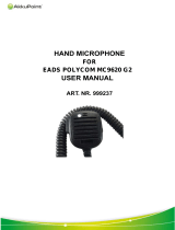
UNIVERSAL DEVICE CONNECTOR
The UDC is located on the side of radio. Various
equipment such as the audio accessories is interfaced by
this connector. The UDC provides an excellent first-
check-point for the initial bench check without the need
to disassemble the unit. Table 2 lists all pins and their
appropriate function. The radio senses the resistance
value between UDC pins 9 and 1 and switches the ap-
propriate circuits to provide proper radio-to-accessory
operation.
Table 2 - UDC Pin Functions
PIN NAME INPUT OR
OUTPUT
USE
1
GROUND ----- Case Ground
3
UDC RX AUDIO Output Test Point For Speaker Audio
4
SW BATT Output Switched Accessory Power
5
EXT PTT Input External Microphone PTT Input
6
TX DATA Input For Programming
7
RX DATA Output For Programming
8
SPARE
9
UDC VOLT ----- Option/Accessory Sense Pin
10
T/R Output Low = Transmit, High = Receive
11
UDC MUTE Output Low = Audio Muted
12
EXT MIC HI Input External Microphone Audio Input
13
EXT EMER Input Lanyard Connection
34
UDC DISCR Output Test Point For RX Audio
Figure 1 - UDC Pin-Out
LBI-38602
8

PROGRAMMING
The radio is programmed using an IBM PC or com-
patible computer. For field programming software is
provided on 5-1/4 floppy and 3-1/2 inch disks. The Pro-
gramming Manual and Software is TQ-3340. This soft-
ware uses a series of screens and windows to guide you
through a programming session. See TQ-3340 for fur-
ther details on programming of the unit.
OPERATION
The EDACS M-PA System model Operators Man-
ual, LBI-38407, gives complete details on the operation
of the unit. Operating procedures are summarized below.
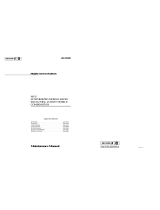
ANTENNA/RADIO/BATTERY ASSEMBLY
If necessary assemble the radio, battery and antenna
into one unit as shown in Figure 2.
1. The antenna (or an antenna adapter) should be inserted
into the top jack. Turn the antenna clockwise until it is
fully seated. If desired the RF Test Connector can be
used in placed of the top antenna. Make sure the antenna
jack is properly terminated before attempting a transmis-
sion.
2. Slide the battery pack (or the dummy battery for bench
checks) onto the bottom of unit until it locks into place.
3. The unit can now be powered-up and tested.
ALERT TONES
The radio uses three basic alert tones to indicate
various operating conditions.
500 Hz - Trunked Failure Tone - Generated when a
trunked failure occurs (call denied, failed
confirmation). - Low battery alert.
1000 Hz - Alert Tone - Generated when a key is
pressed and a status change occurs.
- Channel Access tone - Generated when the
radio is clear to transmit on the assigned
channel.
2500 Hz - Call Queued Tone - Generated when a call
is queued.
SELF-TEST
During the power-up sequence, the radio will per-
form a personality self-test and a pre-programmed test
during which all segments of the LCD will be displayed
momentarily. When the radio passes the self-test, it will
begin operation on the selected group or channel.
If the radio fails the self-test "PERS ERR" will be
displayed. If this happens, the radio requires reprogram-
ming or service.
TRUNKED OPERATION
Digital trunking mode means fast access during
busy hours. In this mode the user selects a communica-
tions group and the communication channel is allocated
through digital signalling with the site.
To Receive A Message
1. Slide the ON/OFF switch on the battery pack to the ON
position. The radio will initiate and complete the self-
test after which the system name and "NC" flag will be
displayed until a control channel is found. When the
control channel is located, the "NC’ flag disappears and
the group name is displayed.
2. Set the Volume Control to mid range.
3. Use the Control Knob or STEP Button to select the de-
sired operating system and/or group (dependent upon
programming). The display indicates the selected group
name.
4. The radio is now ready to receive messages.
5. When the radio receives a group call, it unsquelches on
the assigned channel and lights the "BSY" flag. The
group name or the originators ID (depending on pro-
gramming) is displayed.
See "Special Calls" for details on the reception of indi-
vidual calls.
To Send A Message
1. Turn the radio on, set the receive audio level and select
the desired group.
2. Observe the display for the absence of the "BSY" indi-
cator to ensure no one is transmitting on the selected
group.
LBI-38602
9

3. Press and hold the PTT bar. The radio will then perform
the necessary signalling required to obtain a communi-
cation channel.
4. When the channel has been acquired, the "TX" and
"BSY" flags are displayed and the channel access tone is
heard.
5. Hold the radio approximately three inches from your
mouth and speak into the microphone.
6. Release the PTT bar when the transmission is complete.
Note that if the Carrier Control Timer is enabled, the ra-
dio will unkey and an alert tone will sound if the trans-
mission exceeds the set time.
7. Listen for a reply.
Emergency Operation (Trunked Mode)
Receiving An Emergency Call
1. If the radio receives an Emergency Channel Assignment
in trunked mode, an alert tone sounds and the "EMG"
flag starts flashing. The operator should follow standard
emergency procedures.
Sending An Emergency Call
1. To enable an emergency transmission, press and hold the
Emergency Button for approximately one second. The
radio transmits an emergency message until an Emer-
gency Channel Assignment is received. Upon receipt,
the "EMG" flag is displayed and the radio begins opera-
tion on the assigned group.
2. Press the PTT bar and speak into the microphone in a
normal voice.
3. Release the PTT bar when the transmission is complete
and listen for a reply.
4. When the radio receives a normal group channel assign-
ment, it will return to the previously selected group.
Dynamic Regrouping
Dynamic Regrouping is a feature which allows the
System Manager to dynamically program new groups
into selected radios. Upon development of the regroup-
ing plan, the site controller sends each radio the regroup
plan number, knob setting(s), and activate/deactivate
commands.
When the radio is regrouped, it will alert the user and
the display will indicate "REGRP nn" (nn = 01 - 08 depend-
ing upon the Control Knob setting).
If a regroup (with deselect capability) is active on the
selected system, the user may also select the regroup mode
by pushing the Monitor Button which will toggle back and
forth between group and regroup modes for each pro-
grammed setting of the Control Knob.
CONVENTIONAL OPERATION
For conventional operation the user selects a channel
programmed for conventional use and communicates on that
channel. When the radio is operating on a conventional
channel, the "CNV" status flag appears in the display.
To Receive A Message
1. Slide the ON/OFF switch on the battery pack to the ON
position.
2. Use the Control Knob to select the desired operating
channel.
3. Press the Monitor Button to disable squelch and adjust
the Volume Control for the desired listening level.
4. The radio is now ready to receive messages.
To Send A Message
1. Turn the radio on, set the audio level and select the de-
sired channel.
2. Observe the display for the absence of the "BSY" indi-
cator to ensure that no one is transmitting on the selected
channel. NEVER interrupt another transmission. If
Channel Busy Lockout is enabled, the unit will not
transmit if the channel is busy at PTT time.
3. Press and hold the PTT bar, the "TX" flag will be dis-
played. Speak into the microphone in a normal voice.
Release the PTT bar when the transmission is complete.
The "TX" flag will go out and radio will return to the re-
ceive mode. Note that if the Carrier Control Timer is en-
abled, the radio will unkey and an alert tone will sound
if the transmission exceeds the set time.
Emergency Operation (Conventional Mode)
1. Press the Emergency Button. If programmed, the radio
will switch to the pre-programmed emergency channel,
turn-on the "EMG" flag and perform GESTAR emer-
gency signalling. When GE-STAR signalling is com-
plete the radio will switch back to the selected channel
for communication.
LBI-38602
10

SCAN OPERATION - TRUNKED MODE
Groups which have been previously added to the
scan list may be scanned using this feature.
All scan channels are retained in memory when the
battery pack is removed. The radio will not scan when
the "EMG" flag is on.
Adding (Deleting) Groups To (From) The Scan
List
1. Scan must be off to add (delete) groups to (from) the list.
Note the presence of the "SCN" flag if scan is enabled.
If necessary, toggle scan operation off by pressing the
SCAN Button on the front panel.
2. Select the desired group to be added (deleted) to (from)
the list with the STEP Button and Control Knob. If the
group is presently on the list, the "S" flag will be on.
3. Toggle the "S" flag on or off by pressing the 2nd Button
and then the A/D Button (shifted SCAN Button) on the
front panel. When the "S" flag is on, the group is on the
scan list.
Using Scan
1. To toggle scan operation on, press the SCAN Button.
The "SCN" status flag will turn on when the radio is
scanning.
2. When a group on the list receives a channel assignment,
the radio unsquelches on the assigned channel and the
group name is displayed.
Pressing the PTT Button when scan is enabled will
cause the radio to place the call on the selected group.
If the 2nd and A/D Buttons are pressed while a scanned
call is being received, the group will be deleted from the
scan list.
3. To toggle scan operation off, press the SCAN Button.
The radio will resume operation on the selected group.
SCAN OPERATlON - CONVENTIONAL
MODE
In conventional mode, the radio may be programmed
for a fixed priority-one channel, the selected channel as pri-
ority-one, a fixed scan list, or a front keypad programmed
scan list. The radio supports dual-priority scan operation.
Scan rate will vary depending upon the number of chan-
nels on the scan list and whether or not Channel Guard is
programmed. Fewer channels will result in a faster scan
rate. All scan functions are retained in memory when the
battery pack is disconnected. The radio will not scan when
the "EMG" flag is on.
Scan operation is determined by the following pro-
grammed conditions:
• Dual-Priority Programmed - The priority-one,
priority-two and the remaining channels will be
scanned. Once a carrier is detected and if
programmed, the correct Channel Guard is decoded,
the LCD will indicate the channel. Sampling of the
priority-one and or two channel carrier, regardless
of Channel Guard, be detected while a non-priority
channel is being received, the display name is
updated, the applicable status indicator, "1" or "2"
lights, and the channel is switched to the priority
channel.
• Non-Priority Programmed - Once a carrier is
detected, and if programmed, the correct Channel
Guard is decoded, the display will indicate the
detected channel. Scanning will stop and the radio
will remain on the channel until the carrier ceases.
Scanning will then resume with the selected channel
name displayed.
Adding (Deleting) Channels To (From) The
Scan List
1. Scan must be off to add (delete) channels to (from) the
scan list. Press the SCAN key if the "SCN" status flag is
on.
2. Select the desired channel using the Control Knob
and/or STEP key.
3. Press the 2nd then A/D keys repeatedly (or hold the A/D
key down after pressing 2nd) until the desired priority
indicator appears: "S" for non-priority, "2" for priority-
two, "1" for a priority-one, or no indicator to remove the
channel from the scan list. One of the following mes-
sages may be momentarily displayed:
• "SCAN DIS" - The scan option is disabled. The radio
can not scan unless reprogrammed.
• "FIXED P1" - This programmed option has
designated the priority-one channel. The priority
designation cannot be moved or deleted.
• "FIXD LST" - The fixed scan list option is enabled.
Channels cannot be added (deleted) to (from) the scan
list.
4. To add (delete) additional channels, repeat steps 2 and 3.
LBI-38602
11

Using Scan
Toggle scan on or off by pressing the SCAN key.
The "SCN" flag appears when the radio is scanning.
SPECIAL CALLS
Up to 99 special calls can be prestored in the unit.
Special calls include individual calls and telephone in-
ter-connect calls. These calls are handled via the unit’s
special call mode.
Receiving An Individual Call
When an individual call (call directed only to the ra-
dio) is received, the radio unsquelches on the assigned
channel with the "BSY" flag displayed. The message
"*INDV*", originators ID, or caller’s name is displayed
and the "MSG" flag flashes.
Responding to the call prior to the programmed call-
back time-out will automatically direct the call to the
originating unit.
If no response is returned, "MSG" will remain flash-
ing. To call the unit back, press SPC. The originator’s ID
or name will be displayed. Follow the instructions for
sending a special call.
Sending A Special Call
Special calls may be placed with the radio. Use the
following procedure:
1. Select a special call by following step a or b:
a. Enter the special call’s table location number via the
12-button keypad and press the SPC key. Note that
table location number 1 is the last received individ-
ual caller’s ID number. Location number 2 is the last
received group caller’s ID number. Table locations 3
and higher allow access to the pre-programmed spe-
cial call list in the radio’s personality. If no individ-
ual calls or group calls have been received, the first
two special call table locations will be blank. If a ta-
ble location number larger than the special call table
is entered, the display indicates "RANGE" and the
trunked failure tone sounds.
Figure 2 - Operating Controls
LBI-38602
12

b. Press and release the SPC key. An alert tone sounds
and the "SPC" flag lights. The display changes from
the selected group to the special call display.
Press the STEP or 2nd-STEP keys to scroll through
the special call menu until the desired special call
name appears in the display.
2. Press and hold the PTT bar. The radio performs the nec-
essary signalling required to obtain a communication
channel. When the signalling is complete the "TX" flag
turns on and the channel access tone sounds. Speak into
the microphone in a normal voice.
3. Release the PTT bar when the transmission is complete.
Listen for a reply and repeat step 2 as necessary.
4. When the call is finished, the radio remains in the spe-
cial call menu for a programmed amount of time. To re-
turn to the group selection, press and release the SPC
key. The radio switches to the previously selected group.
Menu Call From Keypad
1. Enter the radio’s individual identification number (the
radio to be called) from the keypad or recall a previously
stored number.
2. Press and hold the PTT bar. The radio will perform nec-
essary signalling required, the "TX" flag will turn on,
and the channel access tone sounds. Speak into the mi-
crophone in a normal voice.
3. Release the PTT bar when the transmission is complete.
Listen for a reply.
4. When the call is compete, the display will continue to
show the radio’s group ID until the special call time-out
expires. To return to group selection, press and release
the SPC key and the radio will return to the previously
selected group.
Telephone Interconnect Call
Telephone calls can be placed with the radio through
the special call failure. Use the following procedure to
initiate and complete telephone calls:
1. Press and release the SPC key. The alert tone sounds, the
"SPC" flag lights and the display changes from the se-
lected group to one of the special call displays.
2. Press the STEP or 2nd-STEP keys to scroll through the
special menu until the desired telephone interconnect ap-
pears in the display.
3. Press and release the PTT bar. The dial-tone, followed
by DTMF tones will be heard.
4. Press the PTT bar to speak when the call is answered.
Unlike a regular telephone, you may not talk and listen
at the same time.
5. To hang-up, press and release the SPC key. Pressing the
Monitor Button also hangs up the call. The radio will re-
turn to the group menu.
Manual Telephone Interconnect Call
1. Enter the telephone number from the keypad. Up to 31
digits can be entered, with the last eight being displayed.
2. Enter an asterisk (*) from the keypad. This indicates to
the radio that the call will be an interconnect type.
3. Press and release the PTT bar to initiate the call. After
necessary signalling is complete, the "BSY" flag turns
on and the channel access tone sounds. The radio enters
receive mode.
If interconnect signalling is not successful, the radio will
return to the idle mode with the telephone number dis-
played until the time-out expires or another system or
group is selected.
4. When the call is answered, press the PTT bar and speak
into the microphone.
5. Release the PTT bar and listen for a reply.
6. When the call is complete, press the SPC button.
OPERATING TIPS
Antenna location and condition is important when using
a UHF radio. Operating the radio in low areas of terrain, un-
der power lines or bridges, inside of a vehicle or in a metal
or steel framed buildings can severely reduce the range of
the unit. Mountains and building can also reduce the range
of the unit.
In areas where transmission or reception is poor, some
improvement may be obtained by insuring that the antenna
is vertical. Moving a few yards in another direction or mov-
ing to a higher elevation may also improve communication.
Vehicular operation can be aided with the use of an exter-
nally mounted antenna.
Battery condition is another critical factor in the trouble
free operation of a portable radio. Observe the procedures
listed in the Service Section to insure the battery packs do
not develop a reduced capacity condition.
LBI-38602
13

INTRINSICALLY SAFE USAGE
Selected portable radios with appropriate factory in-
stalled F4 Options are certified as Intrinsically Safe by the
Factory Mutual Research Corporation for use in Class I, Di-
vision 1 or 2, hazardous locations in the presence of Groups
C and D atmospheres; non-incendive Class I, Division 2,
hazardous locations in the presence of Groups A, B, C, and
D atmospheres.
Hazardous locations are defined in the National Electri-
cal Code. Useful standards NFPA 437A and NFPA 437M
for the classifications of hazardous areas may be ordered
from the National Fire Protection Association, Batterymarch
Park, Quincy, MA 02269.
ACCESSORIES
The accessories listed below are approved for use
with intrinsically safe radios. Use of accessories other
than those listed voids Factory Mutual approval.
• PAAB1A (19B801508P3) Headset/Microphone
• PAAC1A (19B801508P2) Earpiece Kit
• PAAC1B (19B801508P8) GE-STAR Lanyard
• PAAE1A (19B801508P1) Speaker/Microphone
• PAAE1B (19B801508P4) Speaker/Microphone with
GE-STAR Lanyard
• PAAE1C (19B801508P6) Speaker/Microphone/
Antenna
MAINTENANCE
The EDACS M-PA System model radio is a very reliable
unit and will normally provide many years of trouble free
service. The recommended Preventive Maintenance proce-
dures listed below should be performed when a technician
comes in contact with a unit.
Service Section LBI-38604 contains disassembly/reas-
sembly procedures and detailed service procedures which
will aid in board or component level troubleshooting.
PREVENTIVE MAINTENANCE
Antenna
The antenna and antenna contact should be kept
clean and free from dirt or corrosion. If the antenna con-
tact should become dirty or corroded, communication
range could be reduced.
Batteries
Insure the battery packs are properly maintained. Do
not over or under charge the batteries on a regular basis.
Insure the contacts are clean and free of corrosion.
Mechanical
Since portable radio units are subject to shock and
vibration, check for loose plugs, knobs, screws, etc.
Transmitter Check
Check transmit frequency and deviation. Normally
these checks are made when the unit is first put into op-
eration. They should be repeated after the first month of
operation, then annually.
Receiver Check
Receiver sensitivity should be checked periodically
as an indication of overall receiver operation.
Cleaning
If the unit requires an external cleaning use mild
soap and a damp cloth. Avoid abrasive cleaners or
chemicals which may damage the plastic or rubber sur-
faces on the unit.
Printed in U.S.A.
LBI-38602
14

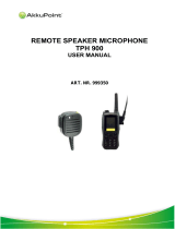
OUTLINE DIAGRAM
Figure 3 - System Model Front Panel And Keypad
(19D438678, Sh. 2, Rev. 10)
LBI-38602
15

BLOCK DIAGRAM
Figure 4 - Rear Cover Assembly
LBI-38602
16

BLOCK DIAGRAM
Figure 5 - Front Cover Assembly
LBI-38602
17
/