Page is loading ...

3Com AP9152 802.11n 2.4/5GHz
Single-Band Access Point
Quick Installation Guide
Model WL-607
3CRWE915275 / 3CRWE9152A75
BOM: 3104XXXX
Manual Version:
APW100
www.3com.com
3Com Corporation
350 Campus Drive,
Marlborough, MA,
USA 01752 3064

Copyright © 2009, 3Com Corporation. All rights reserved. No part of this
documentation may be reproduced in any form or by any means or used to make
any derivative work (such as translation, transformation, or adaptation) without
written permission from 3Com Corporation.
3Com Corporation reserves the right to revise this documentation and to make
changes in content from time to time without obligation on the part of 3Com
Corporation to provide notification of such revision or change.
3Com Corporation provides this documentation without warranty, term, or condition
of any kind, either implied or expressed, including, but not limited to, the implied
warranties, terms or conditions of merchantability, satisfactory quality, and fitness for
a particular purpose. 3Com may make improvements or changes in the product(s)
and/or the program(s) described in this documentation at any time.
If there is any software on removable media described in this documentation, it is
furnished under a license agreement included with the product as a separate
document, in the hard copy documentation, or on the removable media in a directory
file named LICENSE.TXT or !LICENSE.TXT. If you are unable to locate a copy,
please contact 3Com and a copy will be provided to you.
UNITED STATES GOVERNMENT LEGEND
If you are a United States government agency, then this documentation and the
software described herein are provided to you subject to the following:
All technical data and computer software are commercial in nature and developed
solely at private expense. Software is delivered as “Commercial Computer Software”
as defined in DFARS 252.227-7014 (June 1995) or as a “commercial item” as
defined in FAR 2.101(a) and as such is provided with only such rights as are
provided in 3Com’s standard commercial license for the Software. Technical data is
provided with limited rights only as provided in DFAR 252.227-7015 (Nov 1995) or
FAR 52.227-14 (June 1987), whichever is applicable. You agree not to remove or
deface any portion of any legend provided on any licensed program or
documentation contained in, or delivered to you in conjunction with, this User
Guide.
Unless otherwise indicated, 3Com registered trademarks are registered in the
United States and may or may not be registered in other countries.
3Com and the 3Com logo are registered trademarks of 3Com Corporation.
All other company and product names may be trademarks of the respective
companies with which they are associated.
ENVIRONMENTAL STATEMENT

It is the policy of 3Com Corporation to be environmentally-friendly in all operations.
To uphold our policy, we are committed to:
Establishing environmental performance standards that comply with national
legislation and regulations.
Conserving energy, materials and natural resources in all operations.
Reducing the waste generated by all operations. Ensuring that all waste conforms to
recognized environmental standards. Maximizing the recyclable and reusable
content of all products.
Ensuring that all products can be recycled, reused and disposed of safely.
Ensuring that all products are labelled according to recognized environmental
standards.
Improving our environmental record on a continual basis.
End of Life Statement
3Com processes allow for the recovery, reclamation and safe disposal of all
end-of-life electronic components.
Regulated Materials Statement
3Com products do not contain any hazardous or ozone-depleting material.
Environmental Statement about the Documentation
The documentation for this product is printed on paper that comes from sustainable,
managed forests; it is fully biodegradable and recyclable, and is completely
chlorine-free. The varnish is environmentally-friendly, and the inks are
vegetable-based with a low heavy-metal content.

i
About This Manual
Organization
3Com AP9152 802.11n 2.4/5GHz Single-Band Access Points Quick Installation Guide
is organized as follows:
Chapter Contents
1 Product Overview
Introduces the hardware specifications, LEDs, and
interfaces of the 3Com AP9152.
2 Preparing for
Installation
Specifies the temperature and humidity
requirements, power supply for installing the 3Com
AP9152.
3 Installing the AP
Introduces how to install the 3Com AP9152 and
how to connect the power supply by PoE.
4 Connecting to AP
Introduces how to connent to and log into the
3Com AP9152.
Conventions
The manual uses the following conventions:
Symbols
Convention Description
Means reader be extremely careful. Improper
operation may cause bodily injury.
Means reader be careful. Improper operation may
cause data loss or damage to equipment.
Means an action or information that needs special
attention to ensure successful configuration or good
performance.
Means a complementary description.
Means techniques helpful for you to make

ii
Convention Description
configuration with ease.
Obtaining Documentation
You can access the most up-to-date 3Com product documentation on the World Wide
Web at this URL: http://www.3com.com.

iii
Table of Contents
1 Product Overview ....................................................................................................... i
Introduction .............................................................................................................. i
Hardware Specifications .......................................................................................... i
LEDs ............................................................................................................... i
Interfaces ....................................................................................................... ii
2 Preparing for Installation ........................................................................................ iii
Unpacking and Inspection ..................................................................................... iii
Temperature and Humidity Requirements ............................................................ iii
Power Supply ........................................................................................................ iii
3 Installing the AP ....................................................................................................... iv
Determining the Installation Site ........................................................................... iv
Installing the AP ..................................................................................................... iv
Mounting the AP on a Wall ........................................................................... iv
Mounting the AP on a ceiling .............................................................................. viii
Mounting the AP to a T-Rail .................................................................................. ix
Power Supply by PoE ............................................................................................ xi
4 Connecting to the AP ............................................................................................. xii
Approved Channels .............................................................................................. xii
Finding the IP Address on Networks with a DHCP Server(FIT AP) .................... xii
Finding the IP Address on Networks Without a DHCP Server(FAT AP) ............. xii
Log into the AP ..................................................................................................... xii
Converting your Managed AP (FIT) to a Stand-alone AP (FAT) ........................ xiii
Converting your Stand-alone AP (FAT) to a Managed AP (FIT) ........................ xiii

i
Appendix A Product Overview
Introduction
The 3Com AP9152 is an 802.11n access point (AP) product developed by 3Com
Corporation. The AP9152 ships as a FAT AP to provide wireless access independently
without any access controller or serve as a FIT AP (managed) and operate with
wireless local area network (WLAN) switches or access controllers to provide wireless
access for WLAN users. The factory default configuration is FAT mode, and it can
easily be switch between the FIT mode.
Hardware Specifications
The physical dimensions and weight of the AP9152:
Physical dimensions (diameter × thickness) Weight
Φ190 × 60 mm (Φ7.48 × 2.36 in.)
Note: Φ means diameter
0.5 kg (1.10 lb.)
The basic configurations of the AP9152:
Protocols and chassis material Internal antenna
Power
consumption
IEEE 802.11a/b/g/n,
single-RF, plastic mold design
2.4 GHz, gain: 6 dBi
5 GHz, gain: 6 dBi
5.9 W to 7 W
LEDs
When the AP is connected to power, LEDs indicate activities as follows:

ii
LED Color State Description
POWER Green
Steady on The power supply is normal.
Off
The power supply is poorly connected or is
working abnormally.
10/100M
(Ethernet
interface
LED)
Green
Steady on The Ethernet interface is in the link-up state.
Off
The Ethernet interface is in the link-down
state.
Blinking
Data is being transmitted or received at
10/100 Mbps.
1000M
(Ethernet
interface
LED)
Green
Steady on The Ethernet interface is in the link-up state.
Off:
The Ethernet interface is in the link-down
state.
Blinking
Data is being transmitted or received at
1000 Mbps.
2.4G
(Wireless
link LED)
Green
Off
The wireless link is not initialized or the link
is faulty.
Blinking
slowly
The wireless link is working normally
Blinking
rapidly
Data is being transmitted or received.
5G
(Wireless
link LED)
Green
Off
The wireless link is not initialized or the link
is faulty
Blinking
slowly
The wireless link is working normally
Blinking
rapidly
Data is being transmitted or received.
Interfaces
The AP9152 provides a console interface and an Ethernet interface.

iii
Note: The AP9152 provides a reset button and a security slot.
Descriptions of the interfaces on the AP9152:
Interface
silkscreen
Standards and
protocols
Description
CONSOLE RS/EIA-232
The console interface is used for device
configuration and management.
ETHERNET
IEEE802.3
IEEE802.3u
IEEE802.3af
The Ethernet interface can serve as an uplink
interface to access the Internet and as a PoE
interface at the same time.
Caution: When connecting a cable to an interface, pay attention to the interface
silkscreen to avoid connection mistakes.
Appendix B Preparing for Installation
Unpacking and Inspection
Before unpacking the unit, make sure that the package is intact, without any sign of
damage. When unpacking the unit, avoid excessive force, otherwise, the unit inside
the package may get damaged.
After unpacking the unit, check that all items listed on the packing list are contained. If
any of the items are missing, contact your local dealer immediately.
Temperature and Humidity Requirements
The operating temperature and humidity requirements are as follows:
Specification Range
Operating temperature
0°C to 45°C (32°F to 113°F)
Storage temperature
–40°C to +70°C (–40°F to +158°F)
Relative humidity (non-condensing)
5% to 95%
Power Supply
The AP9152 supports PoE power supply.

iv
Appendix C Installing the AP
Note:
1) Make sure that no metal particles (such as screws) fall into the Ethernet or
console interfaces during installation.
2) Before installing the AP9152 to the wall-mounting bracket, connect the
network cable. The network cable can only be UTP cat-5.
3) Before connecting the console cable to the AP9152 for debugging or
pressing the reset button, you need to remove the device from the
wall-mounting bracket.
Determining the Installation Site
Determine the installation site by observing the following principles:
Install the AP in an area away from obstacles that can cause
interference.
Keep the AP far away from electronic devices (such as microwave
ovens) that may generate RF noise.
Ensure that the installation site will not cause any inconvenience or
nuisance.
Note:
1) Make sure the ceiling is strong enough and the structure is suitable in case of
ceiling mounting. Reinforce the ceiling if needed.
2) Us a Kensington lock if physical security is required to protect the AP from
being stolen.
Installing the AP
The AP9152 support three installation methods:
Mounting the AP on a wall
Mounting the AP on a ceiling
Mounting the AP to a T-rail
Mounting the AP on a Wall
The following describes how to mount an AP9152 on a wall:
Installing the wall-mounting bracket on the wall
Installing the AP on the wall-mounting bracket
Locking the AP onto the wall-mounting bracket (optional)
Installing the wall-mounting bracket on the wall

v
Step1 Place the wall-mounting bracket tightly against the wall where the AP is to be
mounted and mark the locations to drill holes for installing the screws. Then
use a drill with a bit of 6 mm (1/4 in) in diameter to drill holes in the wall. The
hole pattern must be identical with that in the wall-mounting bracket.
Highlight:
There are five mounting holes in total in the wall-mounting bracket of the AP9152.
Select the three round holes (with a diameter of 5 mm, or 0.20 in) for the installation.
Figure1 Mounting hole pattern of, the AP9152 wall-mounting bracket:
Step2 Insert the pointed end of wall anchors into the drilled holes and tap the flat end
of wall anchors with a rubber hammer until they are all flush with the wall
surface.
Step3 Align the holes in the wall-mounting bracket with the wall anchors and insert
screws through the mounting holes into the wall anchors, as shown in Figure1.

vi
Figure2 Install the wall-mounting bracket of the AP9152
(1) Drill hole (2) Wall anchor
(3) Wall-mounting bracket (4) Key-hole clip
(5) Screw
Step1 Adjust the position of the wall-mounting bracket and tighten the screws.
Note: Install the wall-mounting bracket with the arrow on the bracket pointing upwards.
Installing the AP on the wall-mounting bracket
Step1 Align the AP with the key-hole clips on the wall-mounting bracket and hang the
AP on the bracket. See callout 1 in Figure3.
Step2 Press or rotate the AP to fix it. See callout 2 in Figure3. Fix the -shaped
holes on the AP’s rear panel to the key-hole clips on the wall-mounting
bracket.

vii
Figure3 Fix the AP9152 onto the wall-mounting bracket
Note: Rotating the AP9152 clockwise installs the device, while rotating it
counterclockwise uninstalls it.
Locking the AP onto the wall-mounting bracket (optional)
The AP9152 has a security slot on the upper left side, which can be used to lock the
AP to a fixed object to prevent theft. Follow these steps to lock the AP to a fixed object:
Step1 Fix the security cable to a nearby fixed object.
Step2 Insert the locking plate in the security slot to lock the AP.
Figure4 Lock the AP9152 to a fixed object
(2)
(3)
(1)
Before installing the security lock: (1) Security slot
After installing the security lock :
(2) Security lock
(3) Security cable
Note: The lock is user supplied.

viii
Mounting the AP on a ceiling
Note:
1) To use this installation method, make sure that the thickness of the ceiling is
less than 18 mm (0.71 in), and the ceiling can bear the weight of at least 5 kg
(11.02 lb.).
2) You are not recommended to use this method to mount the AP to a location
made of low-intensity materials such as a plaster ceiling. If this installation
method is required in such an environment, put a high-intensity plate beneath
the nut to secure the installation.
Select the two mounting holes of the wall-mounting bracket as shown in Figure5 to
mount the AP on the ceiling (in mm). Follow these steps to mount the AP on the ceiling:
Step1 Drill two holes in the ceiling corresponding to the two mounting holes in the
wall-mounting bracket.
Figure5 mounting holes on the wall-mounting bracket
(1) Mounting holes for mounting on a ceiling
Step2 Insert the bolts through the mounting holes of the wall-mounting bracket and
the drilled holes on the ceiling, and then tighten the nuts on the other side of
the ceiling to secure the wall-mounting bracket as shown in Figure6.

ix
Figure6 Mount the wall-mounting bracket on the ceiling
(1) Bolt inside the ceiling (2) Washer
(3) Nut (4) Wall-mounting bracket
(5) Bolt cap (6) Key-hole clip
Step3 Mount the AP9152 to the wall-mounting bracket. For details, refer to Installing
the AP on the wall-mounting bracket.
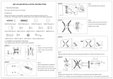
Mounting the AP to a T-Rail
Note: The width of the T-rail must be in the range of 14 mm (0.55 in) to 24 mm (0.94).
Follow these steps to mount the AP to a T-rail:
Step1 Loosen the two M3 × 6 screws on each clip holder until the screw heads are
lower than the upper edge of the nuts (do not remove the screws or they may
get lost).
Step2 Adjust the T-rail clips to make the T-rail holder wider than the T-rail, and then
lock the T-rail with the T-rail holder according to the arrow

x
Figure7 T-rail holder
(1) T-rail clip (2) M4×8 screw nut
(3) M3×6 screw nut (4) Clip holder
(5) M4×8 screw (6) M3×6 screw
(7) Mounting hook (8) T-rail holder
(9) Before installing to the T-rail, loosen the screw nuts until the screw
heads are lower than the upper edge of the nuts.
Step3 Tighten the M3 × 6 screws on the two clip holders until the screw heads touch
the T-rail, and then fix the screws.
Step4 Check that the T-rail holder is fixed to the T-rail.
Step5 Hook the mounting clip of the wall-mounting bracket to the mounting hook of
the T-rail holder, as shown Figure8.
Step6 Insert the two M4 × 8 screws through the two holes (with a diameter of 5 mm,
or 0.20 in) on the wall-mounting bracket according to the dashed line shown in
Figure8 and fix the screws to the T-rail holder.
Step7 Check that the wall-mounting bracket is fixed to the T-rail.
Step8 Install the AP9152 to the wall-mounting bracket. For details, refer to Installing
the AP on the wall-mounting bracket.

xi
Figure8 Mount the AP to the T-rail
(1) M3×6 screw (2) T-rail
(3) Mounting hook (4) T-rail holder
(5) Mounting clip (6) Wall-mounting bracket
(7) Screw hole (8) M4×8 screw
(9) Key-hole clip (10) M4×8 screw
Power Supply by PoE
Power is supplied to the AP9152 through a PoE module or PoE switch. Connect one
end of an Ethernet cable to the Ethernet interface of the AP9152 and the other end to
an Ethernet interface of the PoE device.
Caution: Identify the mark on the device to avoid confusing the console interface for
the Ethernet interface, or vice versa.

xii
Appendix D Connecting to the AP
To connect to the AP, you must first determine the AP’s IP address in one of these
ways.
Approved Channels
Use of this product is only authorized for the channels approved by each country. For
proper installation, select your country from the country-selection list.
To conform to FCC and other country restrictions, your product may be limited in the
channels that are available. If other channels are permitted your country, please visit
the web site for the latest software version. The Appendix B list the Software
Downloads information.
Finding the IP Address on Networks with a DHCP Server(FIT AP)
If your network has a DHCP server, it automatically assigns an IP address to the AP.
Finding the IP Address on Networks Without a DHCP Server(FAT
AP)
If your network does not have a DHCP server, the AP uses a default factory
configuration which includes the following information.
Configure the IP address of the AP as 192.168.0.50.
Configure the AP to enable the Telnet server function (the default
authentication username is admin, password is password, case
sensitive). You can remotely manage and maintain the AP through
Telnet.
Log into the AP
To Log into the AP after you determine its IP address, follows these steps:
1) Connect the AP and PC, and ensure that the PC and AP can communicate
with each other properly.
2) Launch your PC’s web browser. In the address bar, enter your AP’s IP
address and press Enter.
3) At the AP Login Screen, type the user name and password, and the
verification code, select the language (English and Chinese are supported at
present), and click Login. The default username and password are
case-sensitive:

xiii
Username: admin
Password: password
Converting your Managed AP (FIT) to a Stand-alone AP (FAT)
If you plan to run this AP in stand-alone mode, without a wireless controller, go to the
web page at http://www.3com.com to get the FAT firmware and instructions.
Converting your Stand-alone AP (FAT) to a Managed AP (FIT)
If you plan to run this AP in Managed AP mode with a wireless controller, go to the web
page http://www.3com.com to get the instructions.
Table of Contents
A Regulatory Compliance Information .................................................................... E-1
Regulatory compliance standards ....................................................................... E-1
Support Antennas & Accessories information ..................................................... E-1
EU Compliance information ................................................................................ E-1
CE Marking ................................................................................................ E-1
EU Country Restriction in 2.4GHz band ..................................................... E-5
EU Country Restriction in 5GHz band ........................................................ E-5
WEEE Directive–2002/96/EC ..................................................................... E-6
USA Compliance information .............................................................................. E-6
US Federal Communications Commission statement ................................ E-6
RF Requirements ....................................................................................... E-7
Antennas .................................................................................................... E-7
Industry Canada .................................................................................................. E-8
RF Compliance .......................................................................................... E-8
Brazil RF Compliance ......................................................................................... E-9
Korea RF Compliance ......................................................................................... E-9
Taiwan regulatory statement ............................................................................... E-9

E-1
Appendix E Regulatory Compliance Information
Regulatory compliance standards
Table1 Regulatory compliance standards
Discipline Standards
EMC & RF
FCC Part 15.207 & 15.209 & 15.247& 15.205 & 15.407
FCC Bulletin OET-65C
IC RSS 210
ETSI EN 300 328
ETSI EN 301 893
EN 60601-1-2
EN 61000-3-2
EN 61000-3-3
ETSI EN 301 489-1
ETSI EN 301 489-17
Safety
UL 60950-1
CAN/CSA C22.2 No 60950-1
IEC 60950-1
EN 60950-1
Support Antennas & Accessories information
This product can only be used with the supplied antenna(s).
This product does not contain any user serviceable components. Any unauthorized
product changes or modifications will invalidate the warranty and all applicable
regulatory certifications and approvals.
EU Compliance information
CE Marking
/