Page is loading ...

ESPAÑOL
INDICE
DECLARACIÓN “CE” DE CONFORMIDAD ......................................................... 3
1. INFORMACIÓN GENERAL............................................................................ 5
2. DESCRIPCION GENERAL DE LA MAQUINA .................................................. 5
2.1 TRANSPORTE.................................................................................................................6
2.2 PICTOGRAMAS...............................................................................................................6
3. INSTRUCCIONES DE MONTAJE................................................................... 6
3.1 CONDICIONES DE SUMINISTRO.......................................................................................6
3.2 MONTAJE DE LOS ACCESORIOS .......................................................................................7
4. MANTENIMIENTO, INSPECCIÓN Y CONTROL.............................................. 7
4.1 CAMBIO DE LAS CORREAS...............................................................................................7
5. MANDOS .................................................................................................... 7
5.1 PARTES DEL PLATO. .......................................................................................................8
5.2 PIVOTE DE INVERSION Y SELECCIÓN DEL ANGULO.............................................................8
6. PUESTA EN MARCHA Y USO........................................................................ 8
6.1 REALIZACIÓN DEL DOBLADO CON LA ESCUADRA. ..............................................................8
6.2 REALIZACIÓN DEL DOBLADO CON EL DISPOSITIVOS DE ESTRIBOS. .....................................9
7. SOLUCIÓN A LAS ANOMALIAS MÁS FRECUENTES....................................... 9
8. CARACTERÍSTICAS TÉCNICAS.................................................................. 10
9. CAPACIDADES DE DOBLADO. ................................................................... 10
10. CONEXIÓN ELÉCTRICA. .......................................................................... 10
11. RECOMENDACIONES DE SEGURIDAD ..................................................... 10
12. ESQUEMAS ELÉCTRICOS......................................................................... 12
13. GARANTIA.............................................................................................. 15
14. REPUESTOS............................................................................................ 15
15. PROTECCIÓN DEL MEDIO AMBIENTE...................................................... 15
16. DECLARACION SOBRE RUIDOS............................................................... 15
17. DECLARACION SOBRE VIBRACIONES MECANICAS ................................. 15
CERTIFICADO DE GARANTIA........................................................................ 18
4

ENGLISH
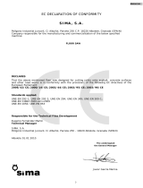
“EC” DECLARATION OF CONFORMITY
S
S
I
I
M
M
A
A
,
,
S
S
.
.
A
A
.
.
er García Marina
Polígono Industrial Juncaril, C/ Albuñol, Parcela 250 C.P. 18220 Albolote, Granada (SPAIN)
Company responsible for the manufacturing and commercialisation of the below specified
machine:
ELECTRICAL STIRRUPS BENDER
That the already mentioned machine, a floor saw designed to cut joints onto asphalt, concrete surfaces and other road
works is in conformity with the provisions of the following EC directives of the European Parliament:
2006/42/CE.
2006/95/CE; 2004/108/CE; 2000/14/CE; 2002/44/CE; 2002/95/CE; 2002/96/CE
Applicable Standards:
UNE-EN 292-1; UNE-EN 292 -2; UNE-EN 294; UNE-EN 349; UNE-EN 60204-1; UNE-EN 1050;
UNE-EN 953
Details of the authorized person to elaborate the technical file
Eugenio Fernández Martín
Technical Manager
SIMA S.A.
Polígono Industrial Juncaril, C/ Albuñol, Parcela 250 - 18220 Albolote, Granada (SPAIN)
Signed
Albolote 01.01.2010 Managing Director
J
a
vi
3

ENGLISH
INDEX
“EC” DECLARATION OF CONFORMITY ............................................................ 3
1. GENERAL INFORMATION............................................................................ 5
2. GENERAL DESCRIPTION OF THE MACHINE................................................. 5
2.1 TRANSPORT ..................................................................................................................5
2.2 PICTOGRAMS ................................................................................................................6
3. ASSEMBLING INSTRUCCIONS .................................................................... 6
3.1 DELIVERY CONDITIONS ..................................................................................................6
3.2 ASSEMBLING THE ACCESSORIES .....................................................................................6
4. MAINTENANCE, INSPECTION AND CONTROL.............................................. 6
4.1 CHANGING THE BELTS....................................................................................................7
5. CONTROL PANNEL...................................................................................... 7
5.1 PARTS OF THE BENDING PLATE........................................................................................7
5.2 INVERSION PIVOT AND ANGLE SELECTION........................................................................7
6. STARTING-UP AND USING THE MACHINE .................................................. 8
6.1 BENDING WITH THE SQUARE...........................................................................................8
6.2 BENDING WITH THE STIRRUPS DEVICE.............................................................................8
7. SOLUTIONS TO MOST FREQUENT ANOMALIES ........................................... 9
8. TECHNICAL CHARACTERISTICS.................................................................. 9
9. BENDING CAPACITY................................................................................... 9
10. ELECTRICAL CONNECTION ..................................................................... 10
11. SAFETY RECOMMENDATIONS ................................................................. 10
12. ELECTRICAL SCHEMES............................................................................ 12
13. WARRANTY ............................................................................................ 15
14. SPARE PARTS......................................................................................... 15
15. ENVIRONMENT PROTECTION ................................................................. 15
16. ACCOUSTIC NOISE DECLARATION.......................................................... 15
17. MECHANICAL VIBRATION DECLARATION............................................... 15
WARRANTY CERTIFICATE ............................................................................ 18
4

ENGLISH
1. GENERAL INFORMATION.
WARNING: Please read and understand perfectly the present instruction before using the machine.
SIMA S.A. thanks you for purchasing its Electrical Stirrup Bender STAR-16.
This manual provides you with the necessary instructions to start, use, maintain and in your case, repair of
the present machine. All aspects as far as the safety and health of the users is concerned have been stated.
Respecting all instructions and recommendations guarantees safety and low maintenance.
As such, reading this manual carefully is compulsory for any person responsible for the use, maintenance or
repair of this machine.
It is recommended to have always this manual in an easily accessible place where the machine is being
used.
.
2. GENERAL DESCRIPTION OF THE MACHINE
The Stirrups Benders Model STAR-16 have been designed and manufactured to bend flat or corrugated steel
bars. The bending operation is done in cold using mandrills to guarantee the bending interior diameter is conforming to
the European norms.
• The reducer is the main element of the machine. It is responsible for transmitting the needed energy
to carry out the steel bars bending.
• The machine is operated by an electrical motor that passes the movement, by a transmission to the
bending mechanism in which the different mandrills are mounted.
• The bending angle can be reached by inserting the pivot in the bending plate. To accurately adjust
the angle, displace the end of course by millimetres.
• The control panel is endowed with polyester, electrical knobs easily identified by pictograms.
• The machine is furnished with a pedal to confirm and execute the manoeuvre, thus avoiding the
upper parts to be trapped while the machine is running.
• The work area is protected by a safety guard to limit possible accidents. This guard is transparent to
allow observing the material being bended, avoiding getting to the upper parts of the bending area.
• The main function of the machine is to bend polygonal stirrups.
• The machine has dismountable legs to ease its transport.
• The electrical switch board complies with the EC norms.
• The machine is painted in oven with a highly resistance, anti-corrosion epoxy polyester paint.
• The electrical equipment with the European Community safety norms.
Any other use of this machine is considered inadequate and can be dangerous. Thus, this is utterly
prohibited.
2.1 TRANSPORT
The machine has been packed on a pallet that makes its transport with trucks or manual pallets transporters
easy. Its weight and other dimensions (See the table of technical characteristics on the present manual) make it
possible to transport the machine in light vehicles.
When it is needed to transport the machine for long distances by vehicles, cranes or other means of elevation,
the latter should be safe.
5

ENGLISH
By lifting the machine with cranes or hoists, normalised slings must be used. These are chosen en function of
the required work load limit, the way of use and the nature of the load. The choice is correct if special norms of use
are respected. Fig. A
WARNING: To avoid any possible danger, stay away from elevated loads and be careful with their possible
displacement during transport, whether during lifting or mooring. Therefore, it is essential to choose the correct slings
and remain particularly vigilant in sensitive operations (elevation, coupling, mooring or discharging).
IMPORTANT
: During the transport of the machine, the latter should never be reversed nor be put on either
side. The machine is only to rest on its four feet.
2.2 PICTOGRAMS
Pictograms included in the machine entail the following:
READ
INSTRUCTIONS
MANUAL
USE HELMET AND EYE AND AUDITIVE
PROTECTION
USE SAFETY BOOTS
USE SAFETY GLOVES
3. ASSEMBLING INSTRUCCIONS
3.1 DELIVERY CONDITIONS
When you open the package, you will find the dismounted machine legs, a user manual with the
corresponding warranty ad a bag with the following elements:
• Four legs
• A bending plate safeguard
• Ruler supporter
• Ruler and two covers
• Dipstick supporter
• A Ø18 bolt, Ø24 bolt, Ø26 bolt and a Ø48 bolt
• To push the bars, there a Ø25 bolt and a Ø36 mandrill
• A stirrups device
• A bending square
3.2 ASSEMBLING THE ACCESSORIES
For transport reasons, the machine is delivered partially mounted. The operator is supposed to mount the
ruler R, Fig. 2, the covers T, Fig. 2, the legs P, Fig. 2, the dipstick supporters V, Fig. 2 and the bending plate
safeguard Q, Fig. 2.
4. MAINTENANCE, INSPECTION AND CONTROL
WARNING: Before performing any operation of maintenance or cleaning, the power supply cable
needs to be disconnected.
• Do not clean the circuits and other electrical elements with a high pressure water.
6

ENGLISH
• Lubricate weekly with calcium grease the holes where the bolts are housed and the bottom of the
of the belts of the motor each 6 months. The correct tightening of the belt is
sed as it has already grease inside for it whole life.
ug it and let a technician review it.
CHANGING THE BELTS
e factory with the belts perfectly tightened. It is possible that the installation of
the mach
1. ake sure the machine is unplugged from the power supply.
.
motor to be displaced.
htening screws.
to be checked and if needed tightened after a certain period
of work as
5. CONTROL PANNEL
lectrical tension entry to the machine.
tion of the rotation of the bending plate.
with
the plate piv
ot tension and has selected a sense
of rotatio
g.5 Orange button: we use this button when we release the pedal, push the emergency button or when
an error i
5.1 PARTS OF THE BENDING PLATE
.6 where to insert the thrust bolt, two twisted holes B, Fig. 6 used to
extract th
5.2 INVERSION PIVOT AND ANGLE SELECTION
ate rotation angle.
bolt to avoid corrosion.
• Review the tension
that which allow a shaft of 1,5 to 2 cm. Fig. 3.
• The reducer group does not need to be grea
• Cables causing breaks or cuts should be urgently changed.
• In case of anomalies in the functioning of the machine, unpl
• At the end of each day, unplug the machine and cover it with a waterproof cloth.
4.1
The machines leave th
ine and by using it for a long time, the belts get loose. To tighten back the belt or replace it, please consider
the following steps.
M
2. Remove the back and front doors of the frame of the machine
3. Loosen with a key the four screws (A, Fig.4) just enough for the
4. Depending on what we want to do, tighten or change the belt, we have to deal with the tig
(B, Fig. . When tightening, make sure all belts have the same tension.
4)
5. Once the belts have been tensed, you can fasten back the screws.
6. Place back the inferior frame safeguard.
IMPORTANT: Transmission belts are
these belts can lose their tightness because of temperature and long hours of work.
A, Fig.5 Switch Plug: e
B, Fig.5 Bending plate direction Selector: It selects the direc
C, Fig.5 Angle adjustment wheel: It is used to regulate the accuracy of the angle that we cannot get
ot. Its function is also to advance or retreat the bar mandrill support.
D, Fig.5 Green pilot: The ignited pilot indicates that the machine has g
n.
E, Fi
n operating the machine happens and we want the bending plate to go back to its point.
F, Fig.5 Emergency stop: It is used to stop the machine in case of emergency.
Pedal. It is used to confirm the rotation of the bending plate. Fig.9
The bending plate has a hole A, Fig
e plate, one hole C, Fig.6 where for the central bolt and a holes sector D, Fig.6 for the inversion pivot.
The inversion pivot (Fig. 8) is used to select the pl
7

ENGLISH
6. STARTING-UP AND USING THE MACHINE
WARNING: All safety recommendations mentioned in the present manual as well as other standard safety
norms as
elwork. They are specially designed for maximum
performance fr
t should be done by a mandrill M, Fig.7 superposed in the thrust
bolt.
NORMAL USE OF THE MACHINE:
en designed for bending flat and reinforced steel bars. Any other use that
has not bee
d to bend bars from Ø 8 to Ø 16mm. the machine is equipped with a set of
Connect the machine to the electricity and make sure the plate turns clockwise.
ntral bolt (B) depending on
epending of the dimensions of the stirrup we want to make.
wish to
he plate and press the pedal. Once the plate has arrived to the end of course, it will
ot get the angel we wish to have, we will have to adjust the angle regulation wheel (R). As such,
BENDING WITH THE STIRRUPS DEVICE
p to 8 mm. It has a Ø25 bolt that needs to be mounted with its
shell and limited to functi
epending on the dimensions of the stirrup we wish to make.
ngle we want to
ar and press the pedal. Once the plate has arrived to its end of course, it will go back to its
le regulation wheel (R). As such,
far as the labour hazards are concerned must be followed.
WHEELWORK: The model STAR-16 does not need any whe
om the first time they are used.
NOTE: when bending, the bar thrus
The stirrups bending machine has be
n expressively indicated is considered abnormal. Any tool or accessory added or amended without written
authorization from the manufacturer is considered inappropriate and dangerous. If any damage or injury is caused as
a result thereof or by misuse of the machine, SIMA S.A. exempts all responsibility as manufacturer. The machine must
be installed on a plane, firm and horizontal surface and the ground should not be soft. This machine DOES NOT HAVE
TO BE USED UNDER THE RAIN. ALWAYS WORK IN WELL ILLUMIINATED AREAS.
6.1 BENDING WITH THE SQUARE
The bending square has been designe
bolts Ø18, Ø24, Ø36, Ø48. These can only be used as central bolt. There is also a fifth bolt Ø25 that needs
always to be mounted with its shell. The latter is limited to be used as a thrust bolt and shell. To start bending,
we will proceed as follows Fig.10.
1.
2. Mount the supporting square (S) and adjust the separating distance from the ce
the diameter of the bar to be bend.
3. Adjust the distance of the tops (T) d
4. Insert the inversion pivot (P) in one of the exterior holes of the plate depending on the angle we
bend. It is recommended to do some tests before starting the real work to get a better command
of the machine.
5. Place the bar on t
automatically return to its original position without needing to the release the pedal. If for any reason we
happen to release the pedal, the plate will stop and we will have to press the orange button to proceed
bending.
6. If we do n
we can obtain the exact angle.
6.2
The stirrups device is designed to bend bars u
on as a thrust bolt and Shell. To start bending, we proceed in the following form Fig.11.
1. Plug the machine and make sure the bending plate is turning clockwise.
2. Mount the stirrups device (S).
3. Adjust the tops distances (T), d
4. Insert the inversion pivot (P) in one of the exterior holes of the plate, depending on the a
bend. It is recommended to make some test before starting to bend to have a better control of the
machine.
5. Place the b
starting point without having to press the pedal. If for any reason we happen to release the pedal, the plate
will stop and we will have to press the orange button to proceed bending.
6. If we do not get the angel we wish to have, we will have to adjust the ang
we can obtain the exact angle.
8

ENGLISH
7. SOLUTIONS TO MOST FREQUENT ANOMALIES
ANOMALY POSSIBLE CAUSE SOLUTION
Loose or damaged belts Tighten belts or change
Cutting/bending power insufficient
Power drop in motor Let the technical service check the
motor
The bending plate turns but only stops
after touching the course end.
Defect end of course
Check the stopping course end and
confirm its continuity. (1 open, 0
closed). Substitute it in case of defect
Check there is tension in the
Faulty tension the machine, the pilot
lamp indicating the state of energy
does not ignite.
Defect electrical connection.
Check switch board at work place
workplace. Check the high and low
tension fuses of the machine switch
board. Check the connection of the
cables.
The LED is on but the machine does
not work.
The machine is not well connected
The machine is connected by one
phase. Check the high tension fuses
of the machine switch board and that
of the work place. Check the
connection of the cables in the switch
board, base and the plug.
230V or 400V connection. It is regular
but the machine would not run.
Unstable tension
Check emission stream exit. If the
voltage is inferior to 230V or 400V the
machine will not run. It is
recommended then to used a tension
stabiliser.
During regression and after bending,
the bending plate does not stop at the
starting point.
End of course
Check the end of course and its
continuity (1 open 0 closed).
8. TECHNICAL CHARACTERISTICS
MODEL MOTOR
POWER
MOTOR
TENSION
NET WEIGHT DIMENSIONS LxAxH
mm
ROTATION/MIN.
STAR-16 2,2Kw 230v 149 Kg. 1136x738x1095 19
STAR-16 1,5Kw 230v / 400v 140 Kg. 1136x738x1095 19
9. BENDING CAPACITY
Resistance of the
steel bars
Nº of bars Ø6
o 1/4"
Nº of bars Ø8
o 5/16"
Nº of bars Ø10
o 3/8"
Nº of bars Ø12
o 1/2"
Nº of bars Ø16
o 5/8"
R-480 N/mm² 7 6 5 3 1
R-650 N/mm² 7 6 5 2 1
Doblado con
mandril de Ø
18 24 36 36 48
9

ENGLISH
10. ELECTRICAL CONNECTION
The extension cable used to feed the machine needs to have a minimum section of 4x2.5 mm
2
up to 25
meters long. For a superior distance 4x4 mm2 can be used. In one of its ends, it is needed to connect a base
normalised ae P+T ó 16A 2P+T comp ine switch and in the ot normalised
aerial pin of 16A 3P+T ó 16A 2P+T compatible with switchboard exit.
nge the position of the bridge plates in th rtant
reflect the change made g the
changing the voltage.
11. SAFETY RECOMMENDATIONS
s to be connected to normalised switch board that is
quipped with a magneto-thermic and a differential that comply with the characteristics of the
3 CV, singl hase at 230v, gneto-the 300mA.
CV, thre at 400V, to-thermi nd a diffe mA.
Stirrups bending machines model Star-16 are to be used by trained people or people familiarized with their
peration.
chine please read the instructions and make sure safety norms are respected.
ine in a fast and safe way.
• Place the machine on a plane surface. Connect the machine to the electricity only when you are sure
ly o a
• It is recommended to use safety glasses, safety boots, gloves etc. Please always use approved
erials.
s use dividual Protec Equipment (IPE in accordance wi the type of wo you are
effectuating.
Prohibit stra ers to access th ce of work of the machine.
• Work clothes are not supposed to have loose articles that can cling into movable parts of the
machine.
• When you have to move the machine, unplug the electricity cables and block the moving parts of the
machine.
• Always keep protection elements and the safety guards in their correct positions.
• Damaged electrical cables should be urgently replaced.
• Unplug the machine from the electricity and never manipulate nor operate on the mechanical nor
electrical elements of the machine while the engine is on.
• Never use the machine for purposes other than those it has been designed for.
rial of 16A 3 atible with the mach her end, one
IMPORTANT: It is appropriate to cha
to change the adhesive labels indicating
machine before
e engine terminals. It is also impo
. It is very important to unplu the voltage, to
• Machines with an electrical motor are alway
e
motor:
2.2KW/
1.5/2
e-p
e-phase
ma
magne
rmic of 20 A and a di
c of 10A a
fferential of 20A/
rential of 10A/300
o
Before starting up the ma
Learn how to stop the mach
• Start the machine on when you have m unted the safety gu rds that come with the machine.
mat
• Alway In tion ) th rk
• ng e pla
10

ENGLISH
VERY IM
s of high temperature, oil, water, sharp edges.
Also avoid trampling or crushing the cables by passing vehicles and do not put any objects on the machine.
• Do not use high pressure water to clean circuits or electrical elements.
PORTANT: Always use earth plug before starting-up the machine.
• Use normalised cables
• Make sure the feeding voltage is in accordance with the voltage indicated in the adhesive label on the machine.
• Make sure that the extension cords are not in contact with point
WARNING: WARNING: You are to follow all safety recommendations mentioned in the present user
manual and comply with all labour risks prevention norms in every location.
SIMA, S.A. is not responsible for the consequences possibly generated but the inadequate use of the stirrups bending machine
model STAR-16.
11

ENGLISH
13. WARRANTY
SIMA, S.A. the manufacturer of light machinery for construction possesses a net of technical services “SERVI-
SIMA”.
Repairs under warranty made by SERVÍ-SIMA are subject to some strict condition to guaranty a high quality
and service.
SIMA S. A. guarantees all its products against any manufacturing defect; to take into account the conditions
stated in the attached document “WARRANTY CONDITIONS”. The latter would cease in case of failure to comply with
the established payment terms. SIMA S.A. reserves its right to bring modifications and changes to its products without
prior notice.
14. SPARE PARTS
The spare parts for the bending and combined machines, manufactured by SIMA, S.A. are to be found in the
spare parts plan, attached to this manual.
To order any spare part, please contact our alter-sales service clearly indicating the serial number of the
machine, model, manufacturing number and year of manufacturing that show on the characteristics plate.
15. ENVIRONMENT PROTECTION
Raw materials have to be collected instead of throwing away residuals. Instruments, accessories, fluids and
packages have to be sent into specific places for ecological reutilisation. Plastic components are marked for
selective recycling.
R.A.E.E. Residuals arising of electrical and electronic instruments have to be stored into specific
places for selective collection.
16. ACCOUSTIC NOISE DECLARATION
These are the acoustic levels emitted by the MACHINE is inferior to 70 dB (A)
17. MECHANICAL VIBRATION DECLARATION
The machine does not generate any mechanical vibrations that present health and workers safety risks.
15

18
ENGLISH
WARRANTY CERTIFICATE AFTER-SALES SERVICE
END USER FORM
NUMBER PLATE
NAME
ADDRESS
POSTAL CODE AND CITY
PROVINCE/COUNTRY
TEL.: Fax:
E-mail
DATE OF PURCHASE
Signature and stamp of the selling party Client signature
WARRANTY CONDITIONS
1.) SIMA, S.A. fully guarantees all its products against defects in design, taking responsibility in the repairs or the faulty equipment for a period of ONE year
from the original date of purchase. The date of purchase must appear on the warranty voucher enclosed.
2.) The warranty covers exclusively labour, repair and substitution of the faulty parts, the model and serial number of which must show on the warranty
certificate.
3.) Transport, stay and food expenses before arriving to SIMA S.A., will be covered by the client.
4.) The warranty does not cover any damage caused by the normal wear, undue usage, overloading, inadequate installation or bad conservation of the
machine.
5.) All repairs under WARRANTY will solely be effectuated by SIMA, S.A. or by its authorised dealers or repair centres.
6.) This Guarantee will be invalid in the following cases:
a) Any Warranty certificate manipulation or modification
b) Repairs, modifications or substitution of any part of the machine by unauthorized parties by SIMA S.A technical department.
c) The non-approved installation of devices by SIMA S.A technical department.
7.) SIMA is not responsible for any damages caused by the failure of the product. This includes, but not limited to, annoyances, transport expenses, telephone
calls and loss of personal goods or commercial benefits, as well as the loss of pay or salary.
8.) Faulty thermal or electrical motors under warranty have to be sent to SIMA S.A or its authorized technical service in the country.
9.) To be benefit from the warranty, the warranty certificate must be at SIMA S.A premises within 30 days from the purchasing date. To claim the warranty,
the purchase invoice has to be attached stamped by the dealer including the serial number of the machine.
CLIENT DETAILS
MACHINE DETAILS
SOCIEDAD INDUSTRIAL DE MAQUINARIA ANDALUZA, S.A.
POL. IND. JUNCARIL, C/ALBUÑOL, PARC. 250
18220 ALBOLOTE (GRANADA)
TEL.: 34 - 958-49 04 10 – Fax: 34 - 958-46 66 45
MANUFFACTRURER OF LIGHT MACHINERY FOR CONSTRUCTION
SPAIN

ENGLISH
WARRANTY CERTIFICATE AFTER-SALES SERVICE
FORM TO R CTRURER ETURN TO MANUFA
DATOS MÁQUINA
NUMBER PLATE
NAME
ADDRESS
POSTAL CODE AND CITY
PROVINCE/COUNTRY
TEL.: Fax:
E-mail:
DATE OF PURCHASE
Signature and stamp of the selling party Client signature
1.) SIMA, S.A. fully guarantees all its products against defects in design, taking responsibility in the repairs or the faulty equipment for a period of ONE year
2.) The warranty covers exclusively labour, repair and substitution of the faulty parts, the model and serial number of which must show on the warranty
4.) The warranty does not cover any damage caused by the normal wear, undue usage, overloading, inadequate installation or bad conservation of the
by SIMA, S.A. or by its authorised dealers or repair centres.
zed parties by SIMA S.A technical department.
7.) SIMA is not responsible for any damages caused by the failure of the product. This includes, but not limited to, annoyances, transport expenses, telephone
9.) To be benefit from the warranty, the warranty certificate must be at SIMA S.A premises within 30 days from the purchasing date. To claim the warranty,
the purchase invoice has to be attached stamped by the dealer including the serial number of the machine.
OR
SOCIEDA A.
POL. IND. 0
A)
5
MANUFFACTRURER OF LIGHT MACHINERY FOR CONST N
SPAIN
DATOS COMPRAD
WARRANTY CONDITIONS
from the original date of purchase. The date of purchase must appear on the warranty voucher enclosed.
certificate.
3.) Transport, stay and food expenses before arriving to SIMA S.A., will be covered by the client.
machine.
5.) All repairs under WARRANTY will solely be effectuated
6.) This Guarantee will be invalid in the following cases:
a) Any Warranty certificate manipulation or modification
b) Repairs, modifications or substitution of any part of the machine by unauthori
c) The non-approved installation of devices by SIMA S.A technical department.
calls and loss of personal goods or commercial benefits, as well as the loss of pay or salary.
8.) Faulty thermal or electrical motors under warranty have to be sent to SIMA S.A or its authorized technical service in the country.
D INDUSTRIAL DE MAQUINARIA ANDALUZA, S.
JUNCARIL, C/ALBUÑOL, PARC. 25
18220 ALBOLOTE (GRANAD
TEL: 34 - 958-49 04 10 – Fax: 34 - 958-46 66 4
RUCTIO
19

FRANÇAIS
INDEX
DECLARATION “CE” DE CONFORMITÉ ............................................................ 3
1. INFORMATION GENERALE.......................................................................... 5
2. DESCRIPTION GÉNÉRALE DE LA MACHINE................................................. 5
2.1 TRANSPORT. .................................................................................................................6
2.2 PICTOGRAMMES. ...........................................................................................................6
3. INSTRUCTIONS DE MONTAGE. ................................................................... 6
3.1 CONDITIONS DE DISTRIBUTION ......................................................................................6
3.2 MONTAGE DES ACCESSOIRES..........................................................................................7
4. ENTRETIEN, INSPECTION ET CONTRÔLE.................................................... 7
4.1 CHANGEMENT DES COURROIES .......................................................................................7
5. COMMANDES.............................................................................................. 7
5.1 PARTIES DU PLATEAU.....................................................................................................8
5.2 PIVOT D'INVERSION ET SÉLECTION DE L'ANGLE.................................................................8
6. MISE EN MARCHE ET UTILISATION............................................................ 8
6.1 RÉALISATION DU CINTRAGE AVEC L'ÉQUERRE. ..................................................................8
6.2 REALISATION DU CINTRAGE AVEC LE DISPOSITIF A ÉTRIERS. .............................................9
7. SOLUTION AUX ANOMALIES LES PLUS COURANTES................................... 9
8. CARACTÉRISTIQUES TECHNIQUES........................................................... 10
9. CAPACITÉS DE CINTRAGE. ....................................................................... 10
10. BRANCHEMENT ÉLECTRIQUE.................................................................. 10
11. RECOMMANDATIONS DE SÉCURITÉ........................................................ 10
12. SCHÉMAS ÉLECTRIQUES......................................................................... 12
13. GARANTIE.............................................................................................. 15
14. PIÈCES DE RECHANGE............................................................................ 15
15. PROTECTION DE L'ENVIRONNEMENT. .................................................... 15
16. CONTAMINATION ACOUSTIQUE ............................................................. 15
17. VIBRATIONS .......................................................................................... 15
CERTIFICAT DE GARANTIE........................................................................... 18
4

ITALIANO
INDICE
DICHIARAZIONE “CE” DI CONFORMITA’........................................................ 3
1. INFORMAZIONE GENERALE........................................................................ 5
2. DESCRIZIONE GENERALE DELLA MACCHINA.............................................. 5
2.1 TRASPORTO. .................................................................................................................6
2.2 PITTOGRAMMI. ..............................................................................................................6
3. ISTRUZIONI DI MONTAGGIO. .................................................................... 6
3.1 CONDIZIONI DI CONSEGNA ............................................................................................6
3.2 MONTAGGIO DEGLI ACCESSORI.......................................................................................7
4. MANUTENZIONE, ISPEZIONE E CONTROLLO. ............................................. 7
4.1 CAMBIO DELLE CINGHIE. ................................................................................................7
5. COMANDI................................................................................................... 7
5.1 PARTI DEL PIATTO. ........................................................................................................8
5.2 PERNO D' INVERSIONE E SELEZIONE DELL' ANGOLO...........................................................8
6. AVVIAMENTO ED USO. ............................................................................... 8
6.1 REALIZZAZIONE DELLA CURVATURA CON LA SQUADRA.......................................................8
6.2 REALIZZAZIONE DELLA CURVATURA CON IL DISPOSITIVO DI STAFFE...................................9
7. SOLUZIONE ALLE ANOMALIE PIU' FREQUENTI........................................... 9
8. CARATTERISTICHE TECNICHE.................................................................. 10
9. CAPACITÁ DI CURVATURA. ...................................................................... 10
10. CONNESSIONE ELETTRICA. .................................................................... 10
11. RACCOMANDAZIONI DI SICUREZZA....................................................... 10
12. SCHEMI ELETTRICI ................................................................................ 12
13. GARANZIA.............................................................................................. 15
14. RICAMBI. ............................................................................................... 15
15. PROTEZIONE AMBIENTALE..................................................................... 15
16. DICHIARAZIONE SUI VALORI ACUSTICI ................................................ 15
17. DICHIARAZIONE SULLE VIBRAZIONI MECCANICHE............................... 15
CERTIFICATO DI GARANZIA......................................................................... 18
4

SOCIEDAD INDUSTRIAL DE MAQUINARIA ANDALUZA, S.A.
POL. IND. JUNCARIL, C/ALBUÑOL, PARC. 250
18220 ALBOLOTE (GRANADA)
Telf.: 34 - 958-49 04 10 – Fax: 34 - 958-46 66 45
FABRICACIÓN DE MAQUINARIA PARA LA CONSTRUCCIÓN
ESPAÑA
/
