14
ENGLISH
• Any engine maintenance should be carried out while the engine is off and cool.
• The technician should bear in mind the safety measures in this manual as well as the guidelines in the
motor´s manual.
• Grease the blade axle every 600 hours of use.
• Check oil level of the motor, always when the motor is horizontal.
• Use the oil recommended by the engine manufacturer.
• For all other maintenance instructions consult the engine manual.
• Clean the machine when necessary and if the machine starts to underperform have a technician look at it.
• Keep the shock absorber pillion clean.
• Don´t forget to remove all tools used for maintenance on the machine before restarting.
• Cover the machine in waterproof material when not in use.
• All modifications to the machine and use of unofficial spare parts are prohibited. SIMA S.A will not be held
responsible for any accidents or incidents caused by modifications made to the machine.
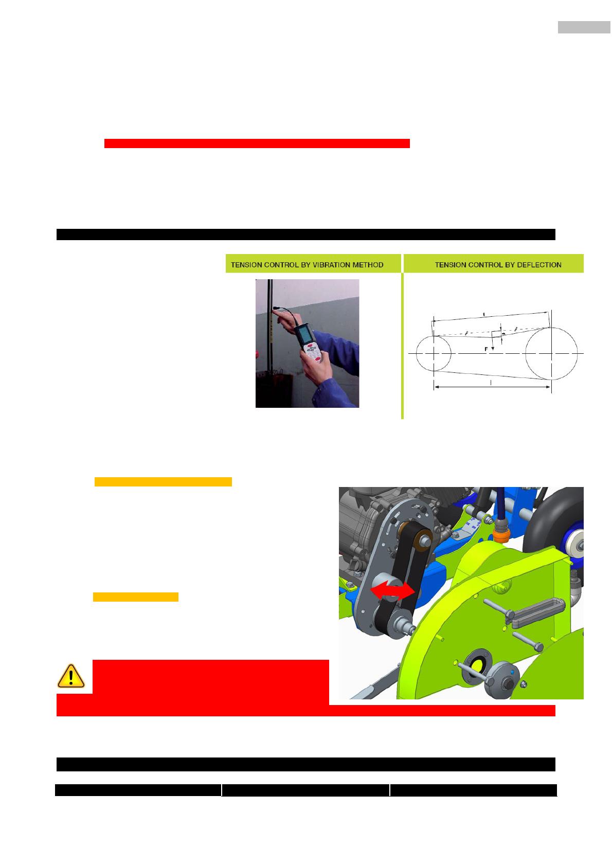
7.1 TIGHTENING OR CHANGING TRANSMISSION BELTS.
Poly V Transmission belts
are parts that over time can become
slack and fall below the permitted
standards of tightness. It is
necessary to check the tightness of
the belts periodically by performing a
simple manual test by prodding the
belt with your finger to check the
tightness, The ´give´ should be
around 8mm.You may check
tightness by a vibrometer or for
deflexion.
The belts can also deteriorate through normal use so it may be necessary to change the belt completely
Procedure to tighten the belt:
1. Remove the blade guard.
2. Loosen the tension pulley screw.
3. Tighten down as shown in the picture.
4. Tighten the tension pulley screw.
5. Replace the blade guard.
Changing the belt:
1. Loosen the tension pulley screw.
2. Move the belt towards the outer rim of the pulley.
Turn the transmission while pushing the belt up
and over the lip to disconnect it.
IMPORTANT: The belts should be checked an
tightened after a full day (8hrs ) use. It is
common for the belt to stretch in the first 8 hrs of
use. After this period the stretching will stop and the belt
will work normally.
8. FREQUENTLY OCCURING ISSUES
PROBLEM POSSIBLE CAUSE SOLUTION


