Page is loading ...

ENGLISH
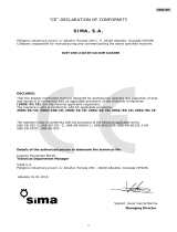
EC DECLARATION OF CONFORMITY
S
S
I
I
M
M
A
A
,
,
S
S
.
.
A
A
.
.
Polígono Industrial Juncaril, C/ Albuñol, Parcela 250 C.P. 18220 Albolote, Granada (SPAIN)
Company responsible for the manufacturing and commercialisation of the below specified
machine:
FLOOR SAW
DECLARES
That the above mentioned floor saw designed for cutting joints onto asphalt, concrete surfaces
and other road works is in conformity with the provisions of the following EC directives of the
European Parliament:
2006/42/CE; 2000/14/CE; 2002/44/CE; 2002/95/CE; 2002/96/CE
Standards applied:
UNE-EN 292-1; UNE-EN 292-2; UNE-EN 294; UNE-EN 349; UNE-EN 500-1;
UNE-EN 13862:2002+A1=2009
UNE-EN 1050; UNE-EN 953
Responsible for the Technical Files Development
Eugenio Fernández Martín
Technical Manager
SIMA, S.A.
Polígono Industrial Juncaril, C/ Albuñol, Parcela 250 - 18220 Albolote, Granada (SPAIN)
Albolote 01.01.2010
The undersigned
the General Manager
Javier García Marina
3

ENGLISH
CONTENTS
EC DECLARATION OF CONFORMITY.....................................................................3
1. GENERAL INFORMATION.................................................................................5
2. DESCRIPTION OF THE MACHINES ...................................................................5
2.1 PICTOGRAMS ..................................................................................................................... 5
3. TRANSPORT ....................................................................................................6
4. ASSEMBLY INSTRUCTIONS..............................................................................6
A. DELIVERY CONDITIONS..................................................................................................... 6
B. HOW TO ASSEMBLE THE HANDLEBAR.ADJUSTABLE POSITION ................................................ 6
C. HOW TO ASSEMBLE THE DEPTH CRANK............................................................................... 6
D. HOW TO PLACE THE BLADE................................................................................................ 6
E. PETROL ENGINE............................................................................................................... 7
SAFETY RECOMMENDATIONS FOR THE MOTOR............................................................................. 7
5. OPERATING INSTRUCTIONS AND USE.............................................................8
F. WATER TANK ................................................................................................................... 8
G. HOW TO USE THE SAW. TURN ON/OFF ................................................................................ 8
H. CUTTING OF MATERIALS ................................................................................................... 8
I. SAFETY RECOMMENDATIONS............................................................................................. 9
6. MAINTENANCE. ...............................................................................................9
J. TENSION OR REPLACEMENT OF THE TRANSMISION BELTS.................................................... 9
K. BLADE FITTING...............................................................................................................10
7. TROUBLESHOOTING GUIDE...........................................................................11
8. TECHNICAL DATA..........................................................................................11
9. WARRANTY ...................................................................................................13
10. SPARE PARTS ..............................................................................................13
11. ENVIRONMENT FRIENDLY...........................................................................13
12. NOISY LEVEL DECLARATION .......................................................................13
13. VIBRATION LEVEL DECLARATION ...............................................................13
14. ELECTRICAL DIAGRAMS ..............................................................................14
WARRANTY CERTIFICATE..................................................................................19
WARRANTY CERTIFICATE..................................................................................21
4

ENGLISH
1. GENERAL INFORMATION
WARNING: before you operate this machine, you must read and study this manual.
SIMA S.A. thanks you for purchasing the FLOOR SAW model COBRA-40/45
This manual provides you with all relevant information about how to use safely use the floor saw as far as service,
maintenance and repairs are concerned. You will also find some relevant data directed to operators covering health and
safety aspects. If all safety instructions are ensured the operator will get a safe service as well as a simple maintenance.
Accordingly it is
of primary importance that the operator understands how to operate this equipment safely (for
the use, maintenance or repairs)
We recommend you to have this manual at hand while the saw is being used
2. DESCRIPTION OF THE MACHINES
• The floor saws SIMA S.A., model COBRA 40/45, are designed and manufactured to cut onto flat surfaces
asphalt, concrete, terrazzo, granite or ceramics. High-speed diamond blades are used and advancement is
manual.
• Any misuse given to the bench saw will be considered as inappropriate and hazardous and remains
forbidden
• Water tank included.
• Security stop button on the chassis keyboard.
• Flexible rubber tires and aluminium rims with double pillow block bearings.
• Blade protection included and dual water cooling feed for blade directly from the water tank or from the mains
inlet.
• Epoxy coating –Polyester to give high resistance to the chassis and keep it from rust
• Guide device to check the straightness of the cutting
• Easy to transport
• Ergonomic design which ease its handle at medium and large sites and guarantees top performance
• Cutting depth gauge for accurate depth of cut
2.1 PICTOGRAMS
Pictograms included in the machine entail the following:
USE HELMET AND EYE AND EAR DEFENDERS
READ INSTRUCTIONS MANUAL
5

ENGLISH
USE SAFETY FOOTWEAR
USE SAFETY GLOVES
3. TRANSPORT
For short distances, the floor saw COBRA 40 can be transported onto its own wheels. Raise the blade fully and
move the saw manually.
When the machine must be lifted, use the hook located on the front part. It will be then easy to fix steel cables or
chains. (See figure 2). Its weight and dimensions make it easy to transport in small vehicles.
WARNING: use highly- resistant cables or chains (bear in mind the weight of the machine and see the metal plate
of the machine).
When the machine will be lowered, do it gently and avoid any strong bumps on the wheels that could damage the
components. Elevate the machine where indicated by the arrow fig. 2.
4. ASSEMBLY INSTRUCTIONS
A. DELIVERY CONDITIONS
The different versions of floor saws model COBRA 40/45 are supplied and single packed into reinforced cardboard
boxes onto a wooden pallet.
With the machine, the operator will find the following components:
• Steel chassis of the machine without blade and with the handlebar removed.
• Handlebar.
• a plastic bag containing a small lever for the adjustable blade wheel, a 4mm Allen key as well as an envelope
with operator manual, the warranty voucher and engine manual.
B. HOW TO ASSEMBLE THE HANDLEBAR.ADJUSTABLE POSITION
The handlebar is dismantled when the machine is delivered because it is easy to fit and also to avoid too much
packaging. To fix it, remove the screws and washers (T, Fig.3) from the chassis of the machine. Place the handlebar (M,
Fig.3) onto the chassis as shown on figure 3 and tighten the screws.
The handlebar of the floor saw COBRA-40/45 has been designed to be adjusted to different types of operators.
How to adjust the handle? Loosen the screws (do not remove them) (T, Fig.4) and use the spanner supplied with
the machine. Use the groove and push manually. The handle will rotate along the screws until it reaches a desired and
comfortable position for the operator. Tighten again the screws. (See Figure 4).
C. HOW TO ASSEMBLE THE DEPTH CRANK
The adjustable depth crank (M, Fig.5) is supplied without the small handle assembled (T, Fig.5) for packaging
reasons and to avoid any breakages during the transport. It is easy to fit: thread it to the crank and use the Allen key 4
mm (A, Fig.5) supplied with the machine.
D. HOW TO PLACE THE BLADE
A good choice ensures performance and improves final results.
Blades must be cooled. Accordingly the floor saw COBRA 40/45 has a water spray system that ensures a steady
stream of water.
6

ENGLISH
The blade guard of the model COBRA 40/45 (P, Fig.6) can be lifted at one of its ends: assembly and blade
replacement are then quick and easy.
To place or change the blade, you must proceed as follows:
• Loosen the screw (A, Fig.6) from the chassis using the 17 mm flat spanner supplied with the machine. There is not
need to remove it completely.
• Raise the blade guard to its maximum onto the screw (B, Fig.6)
• Block the rotation of the blade shaft with the 30 mm spanner (L, Fig.7) provided. The blade shaft has been designed
with two flat faces and thus allows placing the spanner without trouble.
• Loosen the screw of the blade shaft (C, Fig.7) using the 36 mm flat spanner supplied (P, Fig.7) and remove the outer
flange (E, Fig.7). WARNING: the nut is thread on the left.
• Place the blade on the shaft and coincide the small hole with the dowel pin of the inner flange plate. (I, Fig.7).
• Replace the outer flange plate making certain that the dowel pin passes through the blade into the rear flange
plate. Tighten firmly using the two flat spanners provided.
• Close the blade guard on the opposite direction and fix it to the chassis with the screw.
Be sure that the rotation of the tool is always correct. It must coincide with the arrow drawn on the blade as
well as with the arrow painted on the blade guard.
Check that the blade and the flanges adjust perfectly before tightening the nut.
E. PETROL ENGINE
The floor saw model COBRA is supplied without gasoline but with engine oil.
You must follow all the instructions described in the motor manual.
To top up the fuel tank with gasoline, use a funnel or similar so as to avoid hazardous overflows or any leakage that could
affect any component.
Before starting up the motor, check the motor oil level. The machine must be placed onto a flat area with the motor
off, if necessary, complete the necessary level with the correspondent oil type recommended by the manufacturer of the
motor.
SAFETY RECOMMENDATIONS FOR THE MOTOR
• Top up the fuel tank with gasoline, but do not fill excessively, refuelling must be made safely into
ventilated areas.
• Avoid the inhalation of steams issued by the fuel tank.
• Avoid the spilling of fuel, the steams and spilled fuel are under certain conditions highly inflammable
and can catch Fire.
• Do not smoke during the operation and avoid any presence of fire or sparks, even at the place where
the fuel is deposited.
• In case of fuel spilling, clean the work zone and allow the dissipation of steams before starting the
motor up.
• Do not place inflammable elements on the motor.
• Avoid the contact of fuel with the skin.
• Do not allow the use of the motor without the necessary instructions.
• Do not touch and do not allow others to touch the motor while it is still hot. This may cause burns.
• Do not allow children or domestic animals to approach the motor.
• Maintain the fuel out of reach of children.
• Never refuel the engine whilst the engine is ON and do not smoke. Refuelling must be made safely into
ventilated areas.
7

ENGLISH
5. OPERATING INSTRUCTIONS AND USE
Warning: you must follow all the mentioned safety recommendations and comply with the directives about labour
accidents and risks.
F. WATER TANK
The floor saw COBRA 40/45 is supplied with a water tank of 40 litres (D, Fig.8).
HEIGHT REGULATION
The floor saws COBRA are equipped with a height regulation system which is situated on the depth crank located
on the front part of the machine (M, Fig.8). To lower the blade into the cut, turn the control lever in the sense of the
hands of a clock. To raise the blade, do it in the opposite direction as shown on the symbols of the machine (See Figure
8).
The position of the blade is shown on the cutting depth indicator. (A, Fig 8)
To avoid vibrations due to unforeseen rotations of the control lever, the machine is equipped with a simple mechanism
which blockades the control lever onto the desired position (B, Fig.8). Each time that the height regulation is being
modified, you must release the lever.
G. HOW TO USE THE SAW. TURN ON/OFF
To start the engine, proceed as follows:
WARNING: Do not expose the machine to rainfall. Always work at well illuminated work zones.
• Raise the blade until it stays some centimetres above the ground, as indicated in section
• Check the engine oil level. If too low, the engine will not start.
• Open the fuel cock.
• Close the choke. (There is no need to close it if the engine is warm or temperature is high.)
• Place the choke lever halfway.
• Turn the engine stop switch to ON position.
• Turn the machine switch to I position (C, Fig.9).
• Start the engine and pull the handle of the recoil starter.
• Let the engine idle halfway for a couple of minutes and then open the fuel cock. Then open gradually the choke
until fully open.
• To stop the engine, set the speed control lever to the low speed position and place the machine switch to O position (C,
Fig.9). There is no need to turn the engine switch to OFF position because the machine includes an ON/OFF switch
which is more comfortable for the operator.
• Close the fuel cock.
For further details, consult the engine manual.
H. CUTTING OF MATERIALS
Before starting to cut, the following recommendations are to be taken into account:
Start the engine with the blade out of the cutting zone as indicated in section
Place the machine with the blade onto the cutting line and lower the pointer guide (G, Fig.10). This will ease
advancement.
Before starting to cut, open the water tank tap (A, Fig.10). The blade must be cooled properly. An insufficient
cooling could cause an early failure and other damages.
Set the throttle to maximum and plunge the blade slowly as indicated in section until you reach the desired depth. While
the blade lowers, the saw will then have a gentle forward movement to achieve the cut.
Once achieved the desired depth, push gently the saw forward over the pre-determined cutting line. The speed of
travel will be determined by the conditions of the depth, the hardness of material and power motor. If the blade intends
to force or curve it is due to an excessive advancement. Then reduce it.
Do not try to correct the cutting line and force the saw as this will cause damage to the blade or other
components.
8

ENGLISH
To stop the saw, raise the blade from the cutting zone as indicated before. Never stop the saw while the
blade is cutting.
I. SAFETY RECOMMENDATIONS.
Before operating the machine, read carefully the instructions and keep the safety information at hand.
• The floor saws SIMA, S.A. must be used by operators that fully understand how to operate them safely.
• Check that all components are present and secure and that the machine is totally operative.
• Cordon off the machine if all guards are not fitted.
• It is advisable to wear safety goggles, safety footwear and ear defenders. Always use personal protective
equipments
• Keep members of the public and unauthorized personnel at a safe distance.
• Remove any wear clothing that could be caught in the equipments´ moving parts.
• Always switch off the motor before transporting, moving it around the site or servicing it.
• Before starting the motor, check that the blade does not touch the surface being cut.
• Make sure that work areas are adequately ventilated as exhaust fumes produced by the engine are highly toxic.
• Take special care not to touch exhaust pipe while the saw is operating as it can burn. Let it cool for a while after
stopping the engine.
• Keep in mind the safety recommendations of the engine and consult the engine manual for detailed guidance.
• Do not use water under pressure to clean electrical circuits or elements.
• At the end of each working day turn the machine off and disconnect it.
SIMA, S.A. will not be held liable for consequential or other damages in connection with the floor saw COBRA or by
reason of or the inability to use the machine for any purpose.
6. MAINTENANCE.
Maintenance must be done by operators that fully understand how to operate them safely.
• Any maintenance must be carried out while the engine is off.
• Always bear in mind the safety recommendations described in this manual as well as those of the engine manual.
• Lubricate every 80 hours the brackets with bearings the depth screw support bracket and the cutting depth
screw.
• Check the engine oil level and always set the floor saw on level ground. The engines assembled onto the
COBRA 40 are equipped with an alarm that shows a low oil level. When oil level is too low, the engine will not
start. So, fill up as necessary.
• Use oil type SAE 15W- 40.
• Clean frequently the saw and if you observe any anomaly or signs of damage, consult your technicians.
• Do not forget to remove the tools used.
• It is forbidden to modify any components, pieces, elements or characteristics of the machine. SIMA, S.A. will not
be held liable for any consequences due to the non observance of the above recommendations.
• Cover the machine with a waterproof cover.
J. TENSION OR REPLACEMENT OF THE TRANSMISION BELTS.
The transmission belts (C, Fig.10) should be checked after some time and then should be adjusted if necessary.
Check frequently the belt tension and place finger pressure on the top of the belt. The belt should deflect around 8 mm.
Normal wear of the transmission belts can also mean that they should be replaced.
To check the belt tension, remove the belt guard (P, Fig.10) loosening the screws (T, Fig.10) and adjust them
or replace them.
If the belt tension requires adjustment, adjust the engine’s position backwards loosening the nuts (A, Fig.10)
and tighten the screw (R, Fig.10). Once set, tighten again the nuts of the engine.
If the belt tension needs replacement, adjust the engine’s position forward and loosen the nuts and screw R. Then
remove them and replace them. After, adjust again the engine until you reach a correct tension for the belts. Tighten again
the nuts of the engine.
Whenever you remove the belt guard P, check the pulley alignment between the engine pulley and the blade
pulley. Take a ruler, place it and check that there is no room left between.
9

ENGLISH
If the alignment is incorrect, adjust the engine’s position until the pulley is aligned and belt tension is correct.
Finally, replace the belt guard (P, Fig.10) and fix it with its screws.
IMPORTANT
The transmission belts should be checked after 8 working hours and then should be adjusted.
It has been demonstrated that after many working hours the length of the standard-made profile driving belts
increases due to frictions, high temperatures, other tensions, etc….
When the driving of the machine is being made through toothed-made profile flat belts, it is not necessary to
adjust them. In that case, an excessive tension is not appropriate for the correct functioning of the machine.
K. BLADE FITTING
The cutting blade is one of the most important elements of the floor saw. A good blade is fundamental to get an
utmost performance of the machine. Change it ASAP if necessary.
Always use genuine SIMA blades and choose the most appropriate for the material being cut. SIMA S.A. offers you
a wide range for all your applications
10

ENGLISH
7. TROUBLESHOOTING GUIDE
PROBLEM CAUSE REMEDY
Low oil level alert is ON
Top up as necessary
Fuel cock closed
Open fuel cock
The engine will not start
Engine switch or machine switch is
OFF
Turn switches to ON position
Insufficient throttle
Fully open throttle
Belts incorrectly tensioned
Re-tension belts
Excessive advancement
Reduce the advancement
Inappropriate blade
Use the appropriate blade.
Blade not turning and will not cut
Low tension
Revise the engine
Insufficient cooling
Check water flow
Excessive advancement
Reduce the advancement
Early wear of the blade
Inappropriate blade
Use the appropriate blade.
Re-tension belts
Reduce the advancement
Belts are slipping over the pulleys
Use the appropriate blade.
Early wear of the transmission
belts
Pulleys incorrectly tensioned Re –tension pulleys
8. TECHNICAL DATA
DATA COBRA-40-G13H COBRA-40-G13,5R
MOTOR HONDA GX390 ROBIN EH41D
FUEL TYPE Unleaded unleaded
ENGINE START-UP recoil recoil
MAXIMUM POWER 13HP/9,6KW 13,5HP/9,9KW
RPM 3600 R.P.M. 3600 R.P.M.
ADVANCEMENT Manual Manual
Ø BLADE CAPACITY 400 mm 400 mm
Ø BLADE BORE SIZE 25,4 mm 25,4 mm
BLADE MOUNTING Right hand side Right hand side
CUTTING DEPTH 120 mm 120 mm
WATER TANK CAPACITY 40 Litres 40 Litres
COOLING ENTRANCE Blade face Blade face
WEIGHT (UNPACKED) 108 Kg. 108 Kg.
CUTTING DEPTH INDICATOR Mechanical handle and graduated dial Mechanical handle and graduated dial
DIMENSIONS L x W x H (mm) 1580x620x930 1580x620x930
11

ENGLISH
DATA
COBRA-45-G13H COBRA-45-G13,5R
MOTOR HONDA GX390 ROBIN EH41D
FUEL TYPE unleaded unleaded
ENGINE START-UP recoil recoil
MAXIMUM POWER 13HP/9,6KW 13,5HP/9,9KW
RPM 3600 R.P.M. 3600 R.P.M.
ADVANCEMENT Manual Manual
Ø BLADE CAPACITY 450 mm 450 mm
Ø BLADE BORE SIZE 25,4 mm 25,4 mm
BLADE MOUNTING Right hand side Right hand side
CUTTING DEPTH 145 mm 145 mm
WATER TANK CAPACITY 40 Litres 40 Litres
COOLING ENTRANCE Blade face Blade face
WEIGHT (UNPACKED) 108 Kg. 108 Kg.
CUTTING DEPTH INDICATOR Mechanical handle and graduated dial Mechanical handle and graduated dial
DIMENSIONS L x W x H (mm) 1580x620x930 1580x620x930
12

ENGLISH
9. WARRANTY
SIMA, S.A. has got a technical net “SERVI-SIMA” that fully guarantees all its products against defects in design,
taking responsibility in the repairs or the faulty equipment for the warranty period
At the backside of the warranty certificate, all WARRANTY CONDITIONS are specified.
Warning: this warranty certificate will be cancelled in case of unpaid bills.
SIMA, S.A. is free to modify its saws without prior notice
10. SPARE PARTS
The spare parts available for the floor saws model COBRA 40/45, manufactured by SIMA, S.A. are identified in the
spare map included in this manual.
For any spare parts order, contact our After-Sales Service and indicate your part number, model, serial
number and year of manufacturing. (You can find these details on the metal plate on the machine)
11. ENVIRONMENT FRIENDLY.
Raw materials have to be collected instead of throwing away residues. Instruments, accessories, fluids and
packages have to be stored into specific places for ecological reasons. Plastic components must be marked for
selective recycling
R.A.E.E. Residues arising from electrical and electronic instruments have to be stored into
specific places for selective collection.
12. NOISY LEVEL DECLARATION
Level of acoustic power issued by the machine
COBRA-40/G13H LWA (dab) 95
COBRA-40/G13R LWA (dBa) 95
13. VIBRATION LEVEL DECLARATION
Level of exposure time towards vibrations transmitted to hand-arm is:
MODEL LEFT HAND m/ s² RIGHT HAND m/ s²
COBRA-40/G13H 0,00510968383 0,00223113067
COBRA-40/G13R 0,00510968383 0,00223113067
13

ENGLISH
14. ELECTRICAL DIAGRAMS
ELECTRICAL DIAGRAMS COBRA 40-45 G13 Motor Robin
14

ENGLISH
ELECTRICAL DIAGRAM COBRA 40-45 G13 Motor Honda
15

ENGLISH
16

ENGLISH
17

ENGLISH
18

ENGLISH
WARRANTY CERTIFICATE AFTER-SALES SERVICE
COPY FOR THE END USER
MACHINE DATA
Number plate sticker
END USER DATA
NAME
ADDRESS
ZIP CODE
CITY/COUNTRY
Tel.: Fax:
e-mail
PURCHASE DATE
DEALER SIGNATURE CUSTOMER SIGNATURE
WARRANTY CONDITIONS
1.) SIMA, S.A. fully guarantees all its products against defects in design, taking responsibility in the repairs or the faulty equipment for a period of ONE year from
the original date of purchase. The date of purchase must appear on the warranty voucher enclosed.
2.) The warranty covers exclusively labour, repairing and substitution of the pieces considered to be defective by our technical staff .The model and serial number
must be indicated in the warranty certificate
3.) Any other expenses like transport costs, travelling… would be on behalf of the buyer.
4.) The warranty does not cover any damage caused by the normal wear, undue usage, overloading, inadequate installation or bad conservation of the machine.
5.) Only SIMA S.A or any authorized SIMA dealer can repair the faulty machines being SIMA´s technical department which can accept or not the reparation on
warranty. If the reparation or substitution of the pieces is done without SIMA authorisation.
6.) The warranty would be cancelled under the following cases:
a) Any Warranty certificate manipulation or modification
b) Unauthorized by SIMA S.A technical department reparations, modifications or substitution of any part of the machine.
c) Unauthorized by SIMA S.A technical department, not approved devices installation
7.) SIMA S.A. does not assume the responsibility on indirect damages due to machine breakdown, like transport costs, telephone calls, and losing of personal goods
or business, wage or incomes.
8.) In case of breaking down in a motor or engine during the warranty period they have to be send to SIMA S.A or to the technical service authorized in the country
by the manufacturer of themselves
9.) To be benefit of the warranty, the warranty certificate must be in SIMA S.A premises within 30 days period from the purchasing date. To claim the warranty, the
purchasing invoice has to be attached stamped by the dealer including on it the serial number of the machine.
SOCIEDAD INDUSTRIAL DE MAQUINARIA ANDALUZA, S.A.
POL. IND. JUNCARIL, C/ALBUÑOL, PARC. 250
18220 ALBOLOTE (GRANADA)
Telf.: 34 - 958-49 04 10 – Fax: 34 - 958-46 66 45
FABRICACIÓN DE MAQUINARIA PARA LA CONSTRUCCIÓN
ESPAÑA
19

ENGLISH
20

ENGLISH
WARRANTY CERTIFICATE POST-SALES SERVICE
COPY FOR THE END USER
MACHINE DETAILS
Number plate sticker
END USER DETAILS
NAME
ADDRESS
ZIP CODE
CITY/COUNTRY
Tel.: Fax:
e-mail
PURCHASE DATE
DEALER SIGNATURE CUSTOMER SIGNATURE
WARRANTY CONDITIONS
1.) SIMA, S.A. fully guarantees all its products against defects in design, taking responsibility in the repairs or the faulty equipment for a period of ONE year from
the original date of purchase. The date of purchase must appear on the enclosed warranty voucher.
2.) The warranty covers exclusively labour, repair and substitution of the parts considered being defective by our technical staff. The model and serial number must
be indicated in the warranty certificate
3.) Any other expenses like transport costs, travelling… would be on behalf of the buyer.
4.) The warranty does not cover any damage caused by the normal wear, undue usage, overloading, inadequate installation or bad conservation of the machine.
5.) Only SIMA S.A or any authorized SIMA dealer can repair the faulty machines being SIMA´s technical department which can accept or refuse the reparation
under warranty. If the reparation or substitution of the pieces is done without SIMA authorisation.
6.) The warranty would be cancelled under the following cases:
a) Any Warranty certificate manipulation or modification
b) Unauthorized by SIMA S.A technical department reparations, modifications or substitution of any part of the machine.
c) Unauthorized by SIMA S.A technical department, not approved devices installation
7.) SIMA S.A. does not assume the responsibility on indirect damages due to machine breakdown, like transport costs, telephone calls, and losing of personal goods
or business, wage or incomes.
8.) In case of breaking down in a motor or engine during the warranty period they have to be send to SIMA S.A or to the technical service authorized in the country
by the manufacturer of themselves
9.) To be benefit of the warranty, the warranty certificate must be in SIMA S.A premises within 30 days period from the purchasing date. To claim the warranty, the
purchasing invoice has to be attached stamped by the dealer including on it the serial number of the machine.
SOCIEDAD INDUSTRIAL DE MAQUINARIA ANDALUZA, S.A.
POL. IND. JUNCARIL, C/ ALBUÑOL, PARC. 250
18220 ALBOLOTE (GRANADA)
TEL.: 34 - 958-49 04 10 – FAX: 34 - 958-46 66 45
MANUFACTURING LIGHT MACHINERY FOR CONSTRUCTION
21

ENGLISH
22
/
