Page is loading ...

VentilAire™ Roof Depressurization Vent System
Installation Instructions
914117 – Through-the-Roof Vent Kit
These instructions are primarily intended to assist qualified individuals experienced in the proper installation of heating and/or air conditioning appliances. Some local codes
require licensed installation/service personnel for this type of equipment. All installations must be in accordance with these instructions and with all applicable national and local
codes and standards.
Before beginning the installation, read these instructions thoroughly and follow all warnings and cautions in the instructions and on the unit.
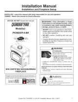
Components Included in Each Kit
Kits conform to H.U.D. manufactured home construction and safety standard paragraphs 3280.103
(b)(2) and 3280.504 (b)(ii) for ventilation.
5" Class I
Insulated Flexible Duct
Plastic
Clamp
Metal
Clamps (2)
Ceiling Grille
Assembly

DESCRIPTION
The roof depressurization vent system is designed to
be used in conjunction with a VentilAire fresh air intake
system in order to comply with the fresh air requirements
outlined in the HUD standard, paragraph 3280.
The vent system releases stale air from inside the home in
order to balance the fresh air supply. It contains a highly
sensitive valve which permits the expulsion of inside
air without pressuring the home (HUD requirement). In
addition, the vent system does not permit back-drafts. The
slightest breeze causes it to close, preventing cold or hot
air from entering the home through the vent.
LOCATION
The depressurization grille should be located on the
ceiling anywhere in the home as long as free air flow to
the vent is unrestricted. A utility room is a good location.
Locating the vent at least eight (8) feet from the furnace
is recommended for best operation.
Determine the location of the roof opening. The roof cap
assembly should be located as closely as possible to
the ceiling grille, to allow connection using the length of
flexible duct provided.
INSTALLATION
WARNING:
DISCONNECT MAIN POWER SUPPLY BEFORE
DRILLING THROUGH THE CEILING. ELECTRICAL
WIRING MAY BE PRESENT.
1. Drill a pilot hole through the ceiling while being careful
to avoid studs or other obstructions. Next, cut a 51/8”
diameter hole in the ceiling.
2. Insert the ceiling grille into the hole and secure it with
the screws provided.
3. Cut a 71/2” diameter opening in the roof at the selected
location.
4. Route the flexible duct through the attic between the
roof opening and the ceiling grille.
5. Attach one end of the flexible duct to the bottom flange
of the roof cap assembly. Secure the inner duct with
one of the metal clamps provided and the insulation
duct with one of the plastic clamps provided.
6. Apply caulking or roof sealing material to the underside
of the roof cap flashing to form a continuous strip about
11/2” in width around the underside of the flashing
perimeter.
7. Attach the roof cap assembly to the roof. Press down
firmly over caulking on the flashing to ensure a waterproof
seal. Secure flashing with appropriate fasteners. As
added protection against leaks, coat the fasteners and
flashing edges with a roofing compound.
8. Pull the flexible duct through the attic space to the ceiling
grille stub while being careful not to kink the duct. Trim
off any excess length of the duct to minimize restrictions.
9. Attach the inner duct to the ceiling grille stub with the
other metal clamp provided. Pull insulation duct down
over stub.
7072220
Specifications & illustrations subject to change without notice or incurring obligations (06/15).
O’Fallon, MO, © Nortek Global HVAC LLC 2015. All Rights Reserved.
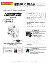
CAULK OR
SEALANT
ATTIC
CEILING
ROOF
ROOF
DEPRESSURIZATION
VENT
/