
C001537_18_CR2_User_Manual 1
Save Settings
Manual Version 18
This version of the manual released with rmware version 4058. Release Date: 3/24/09
User Manual
Code Reader 2.0
™
C001537_18_CR2_User Manual

C001537_18_CR2_User_Manual i
Save Settings
Statement of Agency Compliance
The CR2 can be set to use targeting lasers. The CR2’s targeting laser emits Class 2M
radiation outside of the product per IEC 60825-1. Class 2M Laser/LED product. Do not stare into beam or view directly
with optical instruments.
The CR2 has been tested by an independent electromagnetic compatibility laboratory in accordance with the applicable
specications and instructions.
The CR2 has been tested for compliance with FCC regulations and was found to be compliant with all
applicable FCC Rules and Regulations.
IMPORTANT NOTE: To comply with FCC RF exposure compliance requirements, this device must not be
co-located or operate in conjunction with any other antenna or transmitter.
CAUTION: Changes or modications not expressly approved by the party responsible for compliance could
void the user’s authority to operate the equipment.
The CR2 has been tested for compliance to CE standards and guidelines and was found to conform to
applicable CE standards, specically the EMC requirements EN 55024, ESD EN 61000-4-2, Radiated RF
Immunity EN 61000-4-3, ENV 50204, EFT EN 61000-4-4, Conducted RF Immunity EN 61000-4-6, EN
55022, Class B Radiated Emissions, and Class B Conducted Emissions.
Laser/LED Radiation
Wavelength: <1mW
Maximum Output: 650-700 nm
Laser Pulse Duration: 0.977 mSec.
LED Pulse Duration: 0.255 uSec.
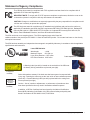
A Warning Label (see left) is located on the underside of the CR2 near
the battery locking mechanism as pictured (see right).
Code voids product warranty if the hard case has been opened or tampered with
in any way. Opening the case may put the user at risk of laser radiation exposure
(Class 3R). A second Warning Label (see left) is placed within the casing struc-
ture as pictured (see right).
Caution – Use of controls or adjustments, or performance of procedures other
than those specied herein may result in hazardous radiation exposure.
In addition, a CB Test Certicate has been issued by the National Certication
Board (NCB) indicating Code Reader 2.0 (CR2) meets all safety and quality stan-
dards in accordance to IEC 60950-1:2001, First Edition.
Enlarged for
readability
Enlarged for
readability
Laser aperature
37AW
E300884
CAUTION - CLASS 3R
LASER RADIATION
WHEN OPEN
AVOID DIRECT EYE
EXPOSURE

C001537_18_CR2_User_Manual ii
Save Settings
Code Reader 2.0 User Manual
Copyright © 2006 Code Corporation.
All Rights Reserved.
The software described in this manual may only be used in accordance with the terms of its license agreement.
No part of this publication may be reproduced in any form or by any means without written permission from Code
Corporation. This includes electronic or mechanical means such as photocopying or recording in information storage and
retrieval systems.
NO WARRANTY. This technical documentation is provided AS-IS. Further, the documentation does not represent a
commitment on the part of Code Corporation. Code Corporation does not warrant that it is accurate, complete or error
free. Any use of the technical documentation is at the risk of the user. Code Corporation reserves the right to make
changes in specications and other information contained in this document without prior notice, and the reader should in
all cases consult Code Corporation to determine whether any such changes have been made. Code Corporation shall
not be liable for technical or editorial errors or omissions contained herein; nor for incidental or consequential damages
resulting from the furnishing, performance, or use of this material. Code Corporation does not assume any product liability
arising out of or in connection with the application or use of any product or application described herein.
NO LICENSE. No license is granted, either by implication, estoppel, or otherwise under any intellectual property rights
of Code Corporation. Any use of hardware, software and/or technology of Code Corporation is governed by its own
agreement.
The following are trademarks or registered trademarks of Code Corporation:
CodeXML, Maker, QuickMaker, CodeXML Maker, CodeXML Maker Pro, CodeXML Router, CodeXML Client SDK,
CodeXML Filter, HyperPage, CodeTrack, GoCard, GoWeb, ShortCode, GoCode, Code Router, QuickConnect Codes
All other product names mentioned in this manual may be trademarks of their respective companies and are hereby
acknowledged.
The software and/or products of Code Corporation include inventions that are patented or that are the subject of patents
pending. U.S. Patents: 6997387, 6957769, 7428981, 6619547, 6736320, 7392933, 7014113, 7240831, 7353999,
7519239, 7204417, 6942152, 7036735, 7070091, 7097099, 7621453
The Code Reader software uses the Mozilla SpiderMonkey JavaScript engine, which is distributed under the terms of the
Mozilla Public License Version 1.1. Source code for this version of Spider Monkey is available at:
http://www.codecorp.com/source/spidermonkey.
The Code Reader software is based in part on the work of the Independent JPEG Group.
Code Corporation, 14940 S. Pony Express Road, Suite 500, Bluffdale, UT 84065
www.codecorp.com

C001537_18_CR2_User_Manual iii
Save Settings
Table of Contents
Chapter 1 - Getting Started ............................................................................................................... 1
1.1 - Introduction ............................................................................................................................ 2
1.2 - Unpacking .............................................................................................................................. 3
1.3 - Reader Battery Installation ..................................................................................................... 4
1.4 - Attaching Handles .................................................................................................................. 5
1.5 - Batch Operation ..................................................................................................................... 6
1.5.1 - Introduction .................................................................................................................. 6
1.6 - Cabled Operation ................................................................................................................... 8
1.6.2 - CR2 as a USB Keyboard ............................................................................................. 9
1.6.2.1 - Addional USB Communication Settings ........................................................... 10
1.6.2.2 - Keyboard Support ............................................................................................ 10
1.6.3 - PS/2 Cable Installation Guide .....................................................................................11
1.6.4 - RS-232 (Serial) Cable Installation Guide ................................................................... 12
1.6.4.1 - Additional RS-232 (Serial) Communication Data Bit Settings .......................... 13
1.6.4.2 - Additional RS-232 (Serial) Communication Baud Rate Settings ...................... 13
1.6.4.3 - Additional RS-232 (Serial) Communication Parity Settings.............................. 13
1.6.5 - Cabled Reader - Time Out Settings ........................................................................... 13
1.7 - Bluetooth Radio Operation ................................................................................................... 14
1.7.1 - Introduction ................................................................................................................ 14
1.7.2 - Bluetooth Radio Auto Connect ................................................................................... 16
1.7.3 - Bluetooth Radio Auto Disconnect ............................................................................... 16
1.7.4 - Bluetooth Radio Time Out Settings ........................................................................... 17
1.7.5 - Bluetooth Radio Out of Range Notication Settings .................................................. 17
1.7.6 - Auto Save Last Bluetooth Address ............................................................................. 17
1.7.7 - Conguration for Belkin Bluetooth Manager Software (Version 1.4.2.10) .................. 18
1.7.9 - Conguration for Microsoft Bluetooth Stack Instructions ........................................... 22
1.7.10 - Installing CodeXML Router Bluetooth Edition for Windows ..................................... 24
1.8 - CR2 Feedback Guide ........................................................................................................... 25
1.9 - Targeting and Reading Techniques ...................................................................................... 27
1.10 - Imager Field of View and Resolution.................................................................................. 28
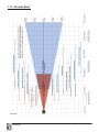
1.11 - Decode Zone ...................................................................................................................... 29
Chapter 2 - Optimization and Trigger Programming .................................................................... 30
2.1 - Introduction .......................................................................................................................... 31
2.2 - Global Trigger Optimization Matrix ....................................................................................... 32
2.3 - Left Trigger Optimization Matrix ........................................................................................... 32
2.4 - Left Trigger Programming .................................................................................................... 33
2.5 - Right Trigger Optimization Matrix ......................................................................................... 33
2.6 - Right Trigger Programming .................................................................................................. 33
2.7 - Handle Optimization Matrix .................................................................................................. 34
2.8 - Handle Trigger Programming ............................................................................................... 34

C001537_18_CR2_User_Manual iv
Save Settings
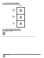
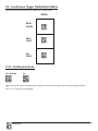
2.9 - Continuous Trigger Optimization Matrix ............................................................................... 35
2.10 - Continuous Scan ................................................................................................................ 35
2.11 - Continuous Scan Settings .................................................................................................. 36
2.11.1 - Continuous Scan - Sleep Time Out .......................................................................... 36
2.11.2 - Continuous Scan - Trigger Delays ............................................................................ 36
2.11.3 - Continuous Scan - Duplicate Scan Delay ................................................................ 36
2.12 - Motion Detection Scan Settings ....................................................................................... 36
Chapter 3 - CR2 Programming: Symbology Settings ................................................................... 37
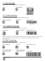
3.1 - Aztec Symbology .................................................................................................................. 38
3.2 - Codabar Symbology ............................................................................................................. 38
3.3 - Codablock F Symbology ...................................................................................................... 38
3.4 - Code 11 Symbology ............................................................................................................. 38
3.5 - Code 39 Symbology ............................................................................................................. 39
3.6 - Code 93 Symbology ............................................................................................................. 39
3.7 - Code 128 Symbology ........................................................................................................... 40
3.8 - Composite Symbologies ...................................................................................................... 40
3.9 - Data Matrix Symbology ........................................................................................................ 40
3.10 - GoCode Symbology .......................................................................................................... 41
3.11 - Interleaved 2 of 5 Symbology ............................................................................................ 41
3.12 - Maxicode Symbology ......................................................................................................... 41
3.13 - Matrix 2 of 5 Symbology ..................................................................................................... 42
3.14 - Micro PDF417 Symbology ................................................................................................. 42
3.15 - MSI Plessy Symbology ...................................................................................................... 42
3.16 - NEC 2 of 5 Symbology ....................................................................................................... 42
3.17 - Optical Character Recognition (OCR) ................................................................................ 42
3.18 - PDF 417 Symbology .......................................................................................................... 43
3.19 - Pharmacode ....................................................................................................................... 43
3.20 - Postal Symbologies ............................................................................................................ 43
3.21 - QR Code Symbology ......................................................................................................... 44
3.22 - GS1 data bar ( formerly RSS) Symbology ......................................................................... 44
3.23 - Telepen Symbology ............................................................................................................ 45
3.24 - UPC/EAN/JAN ................................................................................................................... 45
Chapter 4 - Reader Feedback and Special Settings ..................................................................... 46
4.1 - Volume and Vibration Settings ............................................................................................. 47
4.2 - Code Readability Index ........................................................................................................ 47
4.3 - Laser Settings ...................................................................................................................... 48
4.4 - Reader Power Off Settings................................................................................................... 48
4.5 - Reader ID and Firmware Version ......................................................................................... 49
4.6 - Reader Settings Lock ........................................................................................................... 49
4.7 - Lock-out Link Mode .............................................................................................................. 50
Chapter 5 - Advanced Decode Performance ................................................................................. 51

C001537_18_CR2_User_Manual v
Save Settings
5.1 - Set Targeting Tolerances ...................................................................................................... 52
5.2 - Windowing ............................................................................................................................ 53
5.3 - Mirror Decoding .................................................................................................................... 54
Chapter 6 - Adding a Prex or Sufx and Reader Text Commands ............................................ 55
6.1 - Prex Settings ...................................................................................................................... 56
6.2 - Sufx Settings ...................................................................................................................... 56
6.3 - Erase Prex and Sufx Settings ........................................................................................... 57
6.4 - Reader Text Commands....................................................................................................... 57
Chapter 7 - CR2: Maintenance and Troubleshooting ................................................................... 58
7.1 - Reset Reader to Factory Defaults ........................................................................................ 59
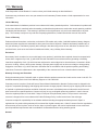
7.2 - General Safety Information .................................................................................................. 59
7.3 - Warranty ............................................................................................................................... 60
7.4 - CR2 Accessories .................................................................................................................. 61
7.5 - Frequently Asked Questions ................................................................................................ 61
7.6 - CR2 Maintenance ................................................................................................................ 61

C001537_18_CR2_User_Manual 1
Save Settings
Chapter 1 - Getting Started

C001537_18_CR2_User_Manual 2
Save Settings
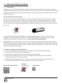
1.1 - Introduction
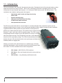
CR2 is a revolutionary bar code and 2-dimensional code reader. Developed to be the rst universal reader, no other
single device performs as many functions. With a cost of ownership far less than comparable systems, the CR2
incorporates a unique dual path optical system, a 1.3 million pixel CMOS sensor, and a 400 MHz processor. This
combination has created a reading system that supports:
• High density matrix codes and larger low density
linear codes
• Superior working range
• High-speed omni-directional decoding
• Cordless and cabled interfaces
• Unsurpassed data read rates
The CR2 sets a new benchmark for size and weight. It is smaller and lighter than comparable systems yet can
withstand multiple drops to concrete. It is the only product available in batch, cabled or wireless formats; handlheld,
ruggedized cabled or battery handle use-case scenarios; and lanyard hook
attachment or reader stand form factors. The cordless version utilizes the latest
Bluetooth™ class 1 radio with a 300 foot operating range. The CR2 is rugged
and lightweight and the cordless version will operate for more than a complete
shift at the highest use rate. The CR2 performs more than 11,000 reads and
transmits from a single battery charge. The CR2 will automatically discriminate
between all major 2-D matrix and linear bar code symbologies and features a
timestamp feature for logging data.
Whether you need a small, palm-held device or a traditional gun, CR2 was
specically developed so users may easily choose the device that best meets
their needs. The CR2 is available in three basic congurations:
1. CR2 Cabled - USB, RS-232 or PS/2 interfaces
2. CR2 Batch - Store and forward device with memory and long-
life battery
3. CR2 Cordless - Long life battery and Bluetooth radio

C001537_18_CR2_User_Manual 3
Save Settings
1.2 - Unpacking
Remove the imager from its packing and inspect it for damage. If the scanner was damaged during shipping, please call
Code at (801) 495-2200.
The standard CR2 unit is shipped with a USB cable interface. The unit also features a battery blank which must be
installed when using the reader (except when attached to the H2, BH1 or BH2 handle).
Various accessories are available for the CR2.
• 4 cable options (USB 6ft., USB 12 ft., RS-232 or PS/2)
• 1950 mAH long-life Lithium-Ion battery
• Class 1 Bluetooth radio with 300 foot operating range (shorter ranges available)
• Clip-on pistol grip handle
• Ruggedized Cabled Handle
• Battery Handle (in two battery sizes)
• External single-bay and two-bay battery charger
• CodeXML Bluetooth modem
• Protective Elastomer Boot
• Protective Case Cover or Holster
• Power Supplies: US/Europe/SA/UK/Asia
• Reader Stand
• Lanyard Hook attachment option
Please keep your packing materials. The CR2 is shipped in an approved shipping container and should be used if you
ever need to return your equipment for servicing.

C001537_18_CR2_User_Manual 4
Save Settings
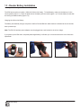
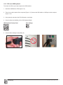
1.3 - Reader Battery Installation
Attaching and Detaching the Lithium Ion Battery
The CR2 has an option to include a 1950 mAH Lithium Ion battery. To install battery, make sure the battery is in the
correct position (gure 1.1). Place the plastic tab of the battery into the reader (gure 1.2). Push the battery in and slide
the locking mechanism down (gures 1.3)
Charging the Lithium Ion Battery
The battery automatically charges everytime a USB or Powered RS-232 cable interface is attached to the unit and the
host is powered up.
Note: The RS-232 interface power adapter must be plugged into a wall socket for the unit to charge.
If you power-up the CR2 with a completely discharged battery it will take up to 10 minutes before the unit will become
operational.
Figure 1.1
Figure 1.3
Figure 1.2

C001537_18_CR2_User_Manual 5
Save Settings
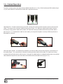
1.4 - Attaching Handles
H1 - Handle
1. Place the CR2 in the cradle of the handle and slide the unit back (Figure 1.4).
Be careful not to place ngerprints on the front glass when attaching handle.
2. Once the 8-pin DIN connector of the handle begins to enter the opening in the back of the unit, rmly
press the unit back until the unit is ush against the handle (Figure 1.5).
Figure 1.4
Figure 1.5
H2 - Ruggedized Cabled Handle
1. Make sure the reader has no battery or battery blank installed.
2. Insert the reader’s 8-pin DIN connector into the exable connector at the back of the H2 handle (Figure
1.6).
3. The reader ‘snaps’ onto the H2 handle utilizing the battery compartment.
4. The reader can be further secured to the handle with two threaded screws through the exible connector
and two more threaded screws on the underside of the reader and handle (Figure 1.7).
BH1 or BH2 Battery Handle
1. Make sure the reader has no battery or battery blank installed.
2. Insert the tab on the back of the BH1 or BH2 Handle into the reader’s recessed slot typically utilized to
secure the battery in place on the reader (Figure 1.8).
3. The reader ‘snaps’ to the handle utilizing the battery compartment (Figure 1.6). The reader will ‘quick
release’ from the handle to accommodate quick and easy battery charging.
4. Optionally, the reader can be further secured to the handle with two threaded screws on the underside of
the reader and handle (Figure 1.7).
Figure 1.8
Figure 1.7
Figure 1.6

C001537_18_CR2_User_Manual 6
Save Settings
1.5 - Batch Operation
1.5.1 - Introduction
The CR2 unit features a batch mode for applications requiring a portable reader. Batch mode allows a user to store
scanned data to the reader’s non-volatile memory. The user may transfer the data to a host computer when needed. To
utilize batch functionality you will need to purchase the 1950 mAH Lithium Ion battery from a Code representative.
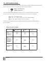
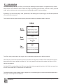
The CR2 may be programmed to operate in three different batch modes:
1. Send & Buffer Mode (Default) - In Send and Buffer Mode, the CR2 unit will automatically detect when
the USB or RS-232 cable is detached, or the Bluetooth® radio is out of range, and will switch into batch
mode and buffer the data in non-volatile memory. When the reader is reconnected to your host computer,
or when the Bluetooth Radio is back in range, the reader will auto transfer the buffered data. Once
transferred, the data is automatically erased from the reader’s memory.
Note: Once a unit is reattached to a cable or enters within radio range, any data scanned WILL NOT
be saved to the non-volatile memory. For RS-232, a power supply connection is used to detect when a
reader is attached to a host computer.
2. Log Only Mode - In Log Only Mode, the reader will only store data into non-volatile memory. You can
only retrieve the data by scanning the Transfer All Stored Data in Memory code (see explanation next
page). Once the reader’s memory has been transferred to a host computer, all of the data will still reside
in memory. A user must scan the Delete Scanned Data from Memory code to clear memory.
3. Send & Log Mode - In Send and Log Mode the reader will save a copy in non-volatile memory as well as
send the data if the reader is connected. The data can be retrieved by scanning the Transfer All Stored
Data in Memory code or the Transfer Only Unsent Data in Memory code (see explanations next page).
Once the reader’s memory has been transferred to a host computer, all of the data will still reside in
memory. A user must scan the Delete Scanned Data from Memory code to clear memory.
Note: The reader can be dened as connected if:
1) The Bluetooth radio is in range;
2) The USB cable is attached to a host and the reader is enumerated;
3) The reader is in RS-232 Cabled - No Power mode; or
4) The RS-232 cable is attached to host with power supply and the reader is in
RS-232 Batch-Cable Detect (Default) mode.
The CR2’s dedicated batch memory is a minimum of 1MB. To determine the number of reads that may be stored, divide
the average bytes of a scan into the total minimum memory.
Feedback
After a successful decode in batch mode, the unit will beep once and the memory LED will ash either red or amber
depending on memory level, and every 15 seconds the battery LED will ash green, amber or red depending on the
battery level. This feedback behavior is accurate when a reader is cabled or uncabled.

C001537_18_CR2_User_Manual 7
Save Settings
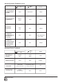
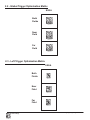
Transferring and Deleting Data
There are three different codes to transfer and delete data in memory.
1. Transfer All Data in Memory - This code will send all data in memory everytime the code is scanned.
2. Transfer Only Unsent Data in Memory - This code will send only the data in memory that hasn’t already been sent
when the code is scanned (ONLY works in Send & Buffer and Send & Log modes).
3. Delete Scanned Data from Memory - Scanning this code will erase all data in the reader’s non-volatile memory.
Auto Transfer Buffer Memory
By default, when reconnected, the CR2 will automatically transfer any data in memory once a connection to a host is
established. If your application is not ready, the reader will send the data anyway and the data could be lost. If you do
not wish for the reader to immediately send data upon connection, please scan the Disable Auto Transfer Buffer Memory
code.
Send & Buffer Mode (Default) Log Only Mode Send & Log Mode
Transfer Only Unsent Delete Scanned Data
Transfer All Data in Memory Data in Memory from Memory
Enable Auto Transfer Disable Auto Transfer
Buffer Memory (Default) Buffer Memory
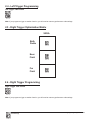
RS-232 Considerations
In RS-233 Cabled-No Power mode, the CR2 will behave as if it is always connected even though the serial cable is
disconnected or the power adapter is unplugged. Data scanned will be sent, regardless of connection status. Data
scanned in Cabled-No Power mode will be lost if the CR2 is not connected to the serial cable - it will not buffer the data,
unless Send & Log or Log Only mode has been enabled.
In RS-232 Batch-Cable Detect (Default) mode, the CR2 will detect if it is connected to a powered serial cable, if it is , it
will then send the data. If a powered serial cable is not connected or if the power adapter is not connected to the serial
cable, the CR2 will buffer the data. When the CR2 is then connected to a powered serial cable, the data will automatically
upload.
RS-232 Batch-Cable Detect (Default) RS-232 Cabled-No Power

C001537_18_CR2_User_Manual 8
Save Settings
1.6 - Cabled Operation
CR2 with Cabled Handle - If a handle was purchased for use with the CR2, the 8-pin DIN connector is at the bottom of
the handle (Figure 1.12). Insert the 8-pin connector and rmly push the cable into the handle. The cable has a locking
mechanism that will rmly hold the cable in place. If using the H2 cabled handle, for additional stability, there is an optional
cable attachment clip that can secure the cable to the handle with two threaded screws (Figure 1.13).
1.6.1- Introduction
The CR2 is a Multi-Interface Unit (MIU) and is available with USB (6 ft. or 12 ft.), RS-232 (Serial) and PS/2 cables (Figure
1.9). All of the cables are connected to the CR2 with a 8-pin DIN connector.
Hand Held CR2 - To install a cable directly to the CR2, correctly line up the 8-pin DIN connector into the back end of the
reader. The arrows on the connector should be facing down (Figure 1.10). When the reader and the cable connector
are lined up, rmly push the cable into the reader. The cable has a locking mechanism that will rmly hold the cable in
place (Figure 1.11). To deattach the cable from the reader, you must pinch the plastic on the 8-pin DIN and pull back to
disengage the connector.
Figure 1.10
Figure 1.11
Figure 1.12
Figure 1.13
Figure 1.9

C001537_18_CR2_User_Manual 9
Save Settings
1.6.2 - CR2 as a USB Keyboard
To connect the CR2 to your host computer via USB interface:
1. Attach the USB cable to CR2 (Figure 1.14).
2. There is no need to power off the computer (Figure 1.15) Connect the USB cable to a USB port on the computer
(Figure 1.16).
3. Once properly connected, the CR2 will power on and beep.
4. Scan the below code (M049_03) for USB Keyboard Mode:
USB Keyboard Factory Reset Save Settings
5. Scan the Save Settings Code (M188_02)
Figure 1.15
Figure 1.16
Figure 1.14

C001537_18_CR2_User_Manual 10
Save Settings
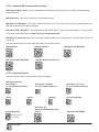
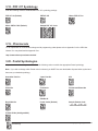
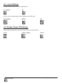
1.6.2.2 - Keyboard Support
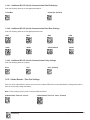
Scan the following codes to set appropriate keyboard mapping:
US English (Default)
No Leading 0 US English - Leading 0 US English - ctrl + char
for non-printable characters for non-printable characters for non-printable characters
French German Japanese Universal Keyboard
Alternative OS
(Windows CE/MAC/Unix/Linux)
Custom Keyboard Enable Alternative OS Disable
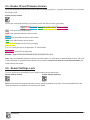
Scan the following codes to set the appropriate USB communication setting:
USB Keyboard USB Downloader USB Native Two Way Mode
USB Virtual COM 1 Way Mode USB HID POS (Terminal ID 131)
1.6.2.1 - Addional USB Communication Settings
USB Keyboard Mode - Data is sent from the Reader and interpreted by the host just as if a USB keyboard was being
used to enter data.
USB Downloader - This mode is used when downloading rmware.
USB Native Two Way Mode - This mode is utilized when there is a need for error-corrected communication between the
CR2 and an application through the USB port.
USB Virtual COM 1 Way Mode - This mode allows a USB-cabled CR2 to function as a virtual COM port. To use the CR2
in this mode, download the driver at www.codecorp.com/downloads.html.
USB HID POS (Terminal ID 131) - This mode allows a USB-cabled CR2 to communicate as a USB HID POS (Terminal ID
131) device.
Requests map to
be installed

C001537_18_CR2_User_Manual 11
Save Settings
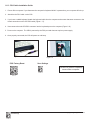
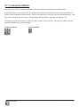
1.6.3 - PS/2 Cable Installation Guide
1. Power off the computer. If you disconnect the computer’s keyboard while it is powered on, your computer will lock up.
2. Attach the the PS/2 cable to the CR2.
3. If you have a cabled keyboard, detach the keyboard cable from the computer and connect that same connector to the
female connection on the CR2 PS/2 cable (Figure 1.17).
4. Now connect the male CR2 PS/2 connector into the keyboard port on the computer (Figure 1.18).
5. Power on the computer. The CR2 is powered by the PS/2 port and does not require a power supply.
6. Once properly connected, the CR2 will power on and beep.
Code does not guarantee compatibility
with all models of computers.
Figure 1.17
Figure 1.18
Save Settings
PS/2 Factory Reset

C001537_18_CR2_User_Manual 12
Save Settings
RS-232 Factory Default Settings
Mode: RS-232 One Way Mode
Baud Rate: 57600
Stop Bits: 2
Data Bits: 8
Parity: None
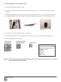
1.6.4 - RS-232 (Serial) Cable Installation Guide
1. Attach the RS-232 (Serial) Cable to the CR2.
2. Connect the RS-232 (Serial) cable to a serial port on the computer (Figure 1.19). There is no need to power off the
computer.
3. The RS-232 (Serial) interface has an optional 5V/1.5A power supply (Figure 1.20). If you have a power supply, plug the
power supply adapter into the RS-232 (Serial) cable and then plug the power adapter into a wall socket (Figure 1.21).
4. Once properly connected, the CR2 will power on and beep.
5. For RS-232 (Serial) mode scan M418_02 (below). If the power supply is not connected scan M074_02 (below).
6. Scan the Save Settings Code (M188_02).
RS-232 (Serial) RS-232 (Serial) Mode
Factory Reset No Power Supply Save Settings
Warning: Code Corporation approved power adapter must be used. Reader failure due to use of incorrect
power adapter will void warranties.
Figure 1.20
Figure 1.19
Figure 1.21

C001537_18_CR2_User_Manual 13
Save Settings
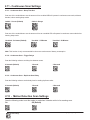
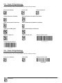
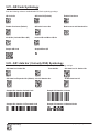
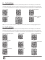
1.6.4.1 - Additional RS-232 (Serial) Communication Data Bit Settings
Scan the following codes to set the appropriate data bit:
7 Data Bits 8 Data Bits (Default)
1.6.4.2 - Additional RS-232 (Serial) Communication Baud Rate Settings
Scan the following codes to set the appropriate baud rate:
1200 2400 4800 9600
19200 38400 57600 (Default) 115200
1.6.4.3 - Additional RS-232 (Serial) Communication Parity Settings
Scan the following codes to set parity:
Even Odd None (Default)
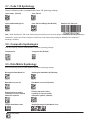
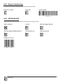
1.6.5 - Cabled Reader - Time Out Settings
Scan one of the codes below to set the amount of time a cabled CR2 will be enumerated before entering sleep mode in
order to more quickly charge the battery:
Note: These settings will only work in versions 2098 and above.
Cabled Reader Time Out: 2 hours Cabled Reader Time Out: Never (Default)

C001537_18_CR2_User_Manual 14
Save Settings
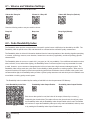
1.7 - Bluetooth Radio Operation
1.7.1 - Introduction
The CR2 features a Bluetooth® wireless radio. The radio allows for point-to-point wireless communication with other
Bluetooth devices that support serial port protocol (SPP). If keyboard entry is necessary, Code XML Router will need to be
installed. The following guide will give you general instructions on connecting your CR2 to a desktop or laptop computer
with a Bluetooth radio.
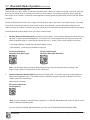
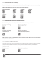
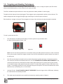
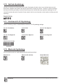
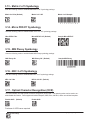
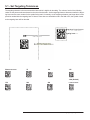
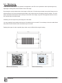
Connecting With A QuickConnect Code
The easiest way to connect to a Bluetooth device is to visit the Code website and create a QuickConnect Code that is
specic to your device (Figure 1.22). This code will link your CR2 directly to the desired Bluetooth device. To create a
QuickConnect Code, you will need to know the Bluetooth address (often referred to as the BD_ADDR) of that device.
You can usually nd the 12-character Bluetooth address somewhere on the device near the device’s serial number (see
Figure 1.23).
If you purchased a CodeXML Bluetooth Modem or a Belkin® Bluetooth adapter from Code or from an authorized
distributor, a QuickConnect Code was included. If you bought a Bluetooth adapter separately and wish to create a
QuickConnect Code, please visit Code’s web site at: http://www.codecorp.com/bdaddr.php.
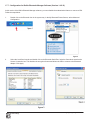
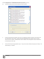
Important Note: You will need to locate the Communications (COM) Port assigned to the Bluetooth serial port protocol.
While installing the Bluetooth Conguration Manager Software that was included with your Bluetooth adapter, make sure
to note the Communications (COM) Port number the software assigned for the adapter (e.g., COM 10). This is the COM
Port through which the CR2 will connect.
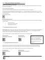
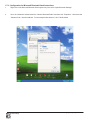
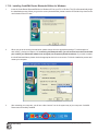
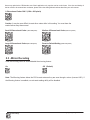
To connect your reader, use the following steps:
1. Power on the CR2 reader by pressing one of the red buttons for one second to power on the reader.
2. Scan the Reset to RF Factory Defaults Code (M684_01).
3. Scan the Quick Connect Code you receieved or created from Code’s website.
4. The CR2 will automatically connect to the computer. By default, the CR2 will beep once after it connects
and beep four times in a row if it did not connect.
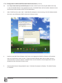
5. Scan the Save Settings Code (M188_02) if you want to save the wireless connection settings to the CR2 so
that the CR2 will automatically try to connect wirelessly the next time it is powered on.
Example:
Reset to RF Factory Defaults QuickConnect Save Settings
Figure 1.22
Figure 1.23
Page is loading ...
Page is loading ...
Page is loading ...
Page is loading ...
Page is loading ...
Page is loading ...
Page is loading ...
Page is loading ...
Page is loading ...
Page is loading ...
Page is loading ...
Page is loading ...
Page is loading ...
Page is loading ...
Page is loading ...
Page is loading ...
Page is loading ...
Page is loading ...
Page is loading ...
Page is loading ...
Page is loading ...
Page is loading ...
Page is loading ...
Page is loading ...
Page is loading ...
Page is loading ...
Page is loading ...
Page is loading ...
Page is loading ...
Page is loading ...
Page is loading ...
Page is loading ...
Page is loading ...
Page is loading ...
Page is loading ...
Page is loading ...
Page is loading ...
Page is loading ...
Page is loading ...
Page is loading ...
Page is loading ...
Page is loading ...
Page is loading ...
Page is loading ...
Page is loading ...
Page is loading ...
Page is loading ...
-
 1
1
-
 2
2
-
 3
3
-
 4
4
-
 5
5
-
 6
6
-
 7
7
-
 8
8
-
 9
9
-
 10
10
-
 11
11
-
 12
12
-
 13
13
-
 14
14
-
 15
15
-
 16
16
-
 17
17
-
 18
18
-
 19
19
-
 20
20
-
 21
21
-
 22
22
-
 23
23
-
 24
24
-
 25
25
-
 26
26
-
 27
27
-
 28
28
-
 29
29
-
 30
30
-
 31
31
-
 32
32
-
 33
33
-
 34
34
-
 35
35
-
 36
36
-
 37
37
-
 38
38
-
 39
39
-
 40
40
-
 41
41
-
 42
42
-
 43
43
-
 44
44
-
 45
45
-
 46
46
-
 47
47
-
 48
48
-
 49
49
-
 50
50
-
 51
51
-
 52
52
-
 53
53
-
 54
54
-
 55
55
-
 56
56
-
 57
57
-
 58
58
-
 59
59
-
 60
60
-
 61
61
-
 62
62
-
 63
63
-
 64
64
-
 65
65
-
 66
66
-
 67
67


Code Code Reader 2.0 User manual
- Category
- Bar code readers
- Type
- User manual
Ask a question and I''ll find the answer in the document
Finding information in a document is now easier with AI
Related papers
Other documents
-
COX HomeLife Thermostat Centralite CCR150243 Battery Replacement Operating instructions
-
Belkin F8T017NG Datasheet
-
Code Corporation CodeXML M3 User manual
-
Code Corporation CodeXML M2 User manual
-
Edic CR2 User guide
-
 Code Corporation CR921-PKR Datasheet
-
Code Corporation CR3500 User manual
-
-
Audiovox CA2051 Warranty Card
-
 Code Alarm CR3 User manual

