Page is loading ...

COMMAND PROCESSOR
MODEL 1712
INSTALLATION GUIDE
LT-0051 (6/90)


COMMAND PROCESSOR
MODEL 1712
INSTALLATION GUIDE
FCC NOTICE
This equipment generates and uses radio frequency energy and if not installed and used properly, that is, in strict
accordance with the manufacturer's instructions, may cause interference to radio and television reception. It has been
type tested and found to comply with the limits for a Class B computing device in accordance with the specifications in
Subpart J of Part 15 of FCC Rules, which are designed to provide reasonable protection against such interference in
a residential installation. If this equipment does cause interference to radio or television reception, which can be
determined by turning the equipment off and on, the installer is encouraged to try to correct the interference by one or
more of the following measures:
Reorient the receiving antenna
Relocate the computer with respect to the receiver
Move the computer away from the receiver
Plug the computer into a different outlet so that computer and receiver are on different branch circuits.
If necessary, the installer should consult the dealer or an experienced radio/television technician for additional
suggestions. The installer may find the following booklet prepared by the Federal Communications Commission helpful:
“How to Identify and Resolve Radio-TV Interference Problems”.
This booklet is available from the U.S. Government Printing Office, Washington, DC 20402.
Stock No. 004-000-00345-4.
Copyright © 1986 Digital Monitoring Products, Incorporated
Information furnished by DMP is believed to be accurate and reliable.
This information is subject to change without notice.

TABLE OF CONTENTS Section
1PRODUCT SPECIFICATIONS
Description ................................................................................................ 1.1
Enclosure Specifications ........................................................................... 1.2
Circuit Board and Coverplate .................................................................... 1.3
Lightning Protection .................................................................................. 1.4
2COMMUNICATION MODULE CONNECTOR
Description ................................................................................................ 2.1
FCC Registration....................................................................................... 2.2
Notification ................................................................................................ 2.3
3RESET JUMPER J13
Description ................................................................................................ 3.1
4SYSTEM GROUND
Terminal 3 ................................................................................................. 4.1
5GROUND SUPERVISION
Terminal 11 ............................................................................................... 5.1
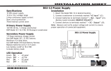
6PRIMARY POWER SUPPLY
Terminals 1 & 2 ......................................................................................... 6.1
Transformer............................................................................................... 6.2
7SECONDARY POWER SUPPLY
Battery....................................................................................................... 7.1
Battery Only Restart.................................................................................. 7.2
Replacement Period.................................................................................. 7.3
Discharge/Recharge ................................................................................. 7.4
Battery Supervision ................................................................................... 7.5
Battery Cutoff ............................................................................................ 7.6
1712 Power Requirements........................................................................ 7.7
8BELL OUPUT
Terminal 4 ................................................................................................. 8.1
2 Amp fuse ................................................................................................ 8.2
9SMOKE DETECTOR OUTPUT
Terminal 6 ................................................................................................. 9.1
1 Amp Fuse............................................................................................... 9.2
10 KEYPAD, LOOP EXPANDER INSTALLATION
Description .............................................................................................. 10.1
Terminal 7 - RED............................................................................... 10.2
Terminal 8 - YELLOW ....................................................................... 10.3
Terminal 9 - GREEN ......................................................................... 10.4
Terminal 10 - BLACK .......................................................................... 10.5
11 PROTECTION LOOPS
Description .............................................................................................. 11.1
Operational Parameters .......................................................................... 11.2
Loop Response Time .............................................................................. 11.3
12 DRY CONTACT RELAY OUTPUTS
Description .............................................................................................. 12.1
Contact Rating ........................................................................................ 12.2
Relay Expansion ..................................................................................... 12.3
13 PROGRAMMER CONNECTOR
Description .............................................................................................. 13.1

Page 1
1712 INSTALLATION GUIDE
1 - PRODUCT SPECIFICATIONS
1.1 Description
The COMMAND PROCESSOR series 1712 is a 12 volt Alarm Control Panel. The Control provides eight
or sixteen class B grounded protection loops and two to eight dry contact SPDT (form C contact) relay
outputs. It is available in four different models.
Model 1712A 8 Loops 2 Relays
Model 1712B 16 Loops 2 Relays
Model 1712C 16 Loops 4 Relays
Model 1712D 16 Loops 8 Relays
All controls provide a two amp alarm output and a one amp auxiliary output. Communication to a central
station receiver is accomplished by addition of a series 984 Communication Module.
1.2 Enclosure Specifications
The 1712 is shipped installed in its enclosure. The transformer, end of line resistors, battery leads,
installation guide and programming sheets are also included.
Size: 14.85" x 12.75" x 4.80"
Weight: 12 lbs.
Color: Beige
Construction: 20 gauge cold rolled steel
Knockouts: Four .875" knockouts (2 on top, 2 on back)
One on door for DMP Model 301 Lock (sold separately)
Slots: Three .5" x 7.0" slots on back

Page 2
121812 INSTALLATION GUIDE
1712 INSTALLATION GUIDE
1.3 Circuit Board and Coverplate
The 1712 coverplate labels the locations of the installation points described in this manual. A short
specification is provided where appropriate. For complete specifications refer to this manual.
1.4 Lightning Protection
Metal Oxide Varistors and Transient Voltage Suppressors help protect against voltage surges on input
and output circuits of the 1712. Additional surge protection is available by installing the DMP Model
370 Lightning Suppressor.
Communication Module Connector

Page 3
1712 INSTALLATION GUIDE
2 - COMMUNICATION MODULE CONNECTOR
2.1 Description
One 25 pin connector is provided for connection of a DMP series 984 Communication Module. The
module should always be in place before power is applied to the control panel.
NEVER INSTALL OR REMOVE A COMMUNICATION MODULE WHILE
POWER IS APPLIED TO THE CONTROL PANEL
Refer to the appropriate installation guide supplied with the 984 Communication Module for installation
and wiring instructions.
2.2 FCC Registration
The Model 1712 and 984 comply with FCC part 68 and are registered with the FCC.
Registration number: CCK8GW-68626-AL-R Ringer Equivalence: 0.0B
2.3 Notification
Registered terminal equipment must not be repaired by the user. In case of trouble, the device must
be immediatley unplugged from the telephone jack. The factory warranty provides for repairs.
Registered terminal equipment may not be used on party lines or in connection with coin telephones.
Notification must be given to the telephone company of:
a. The particular line(s) to which the service is connected
b. The FCC registration number
c. The ringer equivalence
d. The make, model and serial number of the device
3 - RESET JUMPER J13
3.1 Description
The reset jumper is located at the top right hand side of the 1712 as shown in the figure below. It is used
to reset the microprocessor of the 1712. The jumper should be placed in the reset (R) position when
power is applied and removed from the control. The jumper should be placed in the normal operating
position, after power is applied, for system operation.
J13
J13
RReset Position
R
Normal Operating
Position
Programmer
Connector

Page 4
121812 INSTALLATION GUIDE
1712 INSTALLATION GUIDE
4 - SYSTEM GROUND
4.1 Terminal 3
Terminal 3 of the Model 1712 must be connected to earth ground. A cold water pipe or ground rod is
recommended. An electrical conduit ground is not recommended. A 14 gauge wire should be used for
grounding.
5 - GROUND SUPERVISION
5.1 Terminal 11
The system ground connected to Terminal 3 can be monitored by Terminal 11, Ground Supervision. A 24
gauge wire should be connected from Terminal 11 to a second ground clamp on the ground source. A break
in either the ground wire or the ground supervision wire will then be detected by the 1712.
6 - PRIMARY POWER SUPPLY
6.1 Terminals 1 & 2
The transformer for the 1712 should be connected to Terminals 1 and 2 at the top right hand side of the circuit
board. A 16 to 18 gauge wire should be used between the transformer and the 1712.
6.2 Transformer
The 1712 is supplied with one 14 VAC 40 VA transformer, (DMP Model 317). The transformer should be
plugged into a 120 VAC 60 Hz commercial power outlet when system installation is complete. The outlet
should not be controlled by a wall switch. Never share the transformer output with any other equipment.
7 - SECONDARY POWER SUPPLY
7.1 Battery
A 12 VDC 6AH sealed lead-acid rechargeable battery, (DMP Model 367) should be connected to the battery
leads located at the lower right side of the circuit board. Observe polarity when connecting battery. The
negative terminal of the battery is connected to the case ground internally. A second battery may be
connected by adding a dual battery harness, (DMP Model 318). Use sealed lead-acid rechargeable batteries
supplied by DMP or manufactured by Eagle Picher or Yuasa to insure proper charging. DO NOT USE GEL
CELL BATTERIES.
7.2 Battery Only Restart
When powering up the 1712 control without AC power it is necessary to short the Battery Only Restart pads
together to pull in the battery cutoff relay. The Battery Only Restart pads are located on the right side of the
circuit board just below the relay four terminals. The pads need a momentary short only, once the relay has
pulled in the battery power will hold it in that condition. If the 1712 control is powered up with the AC trans-
former the battery cutoff relay is pulled in automatically.
7.3 Replacement period
The battery manufacturer recommends that the battery be replaced every 3 to 5 years under normal use.
7.4 Discharge/Recharge
The 1712 battery charging circuit is a float charge at 13.8 VDC at a maximum current of 1.2 amps. The total
current available will be reduced by the total auxiliary power draw from Terminals 6 & 7. The various battery
voltage levels are listed below:
Battery Trouble 11.9 VDC
Battery Cutoff 10.0 VDC
Battery Restored 12.6 VDC

Page 5
1712 INSTALLATION GUIDE
7.5 Battery Supervision
The 1712 will test the battery once every hour when AC power is still present. The test is done at 15 minutes
past the hour and lasts for 5 seconds. A load is placed on the battery and if the battery voltage falls below
11.9 VDC a low battery is detected. If AC power has failed, a low battery will be detected any time the
battery voltage falls below 11.9 VDC.
If a low battery is detected with AC power still present the test will be repeated every two minutes until the
battery reaches 12.6 VDC; the battery restored voltage. If a faulty battery is replaced with a fully recharged
battery the restored battery will not be detected until the next two minute test is done.
7.6 Battery Cutoff
The battery will be disconnected from the 1712 anytime the voltage of the battery drops to 10.5 VDC. This
is to prevent deep discharge damage to the battery.
7.7 1712 Power Requirements
When AC power has failed the 1712 control and all auxiliary devices connected to the 1712 draw their power
from the battery. All devices must be taken into consideration when calculating the desired standby battery
capacity. Below is a list of the power requirements of the 1712 control and 984 Communication Module.
Add the additional current draw of SECURITY COMMAND keypads, loop expanders and any other auxiliary
devices used in the system for the total current required.
1712 Control 180 ma
Relay output on 25 ma
1K Protection Loop 2 ma
984 Communicator 35 ma
8 - BELL OUTPUT
8.1 Terminal 4
10.5 to 15 VDC is supplied at Terminal 4 to power an alarm bell or horn. This output can be steady or pulsed
depending upon the Bell Action specified in Output Options with the 854 Programmer. Terminal 5 is the
ground reference for the bell circuit. Devices connected to this terminal must operate over a range of 10.5
to 15 VDC.
The bell circuit is supervised and an open circuit will be detected. A low current supply will be present on
Terminal 8 for supervision.
8.2 2 Amp Fuse
The Bell Output is current limited with a 2 Amp fuse. It is the left fuse located at the middle right hand side
of the circuit board. The 2 amp fuse is a Type SFE 1/4" x 5/8" fast blow, (DMP Model 315).
9 - SMOKE DETECTOR OUTPUT
9.1 Terminal 6
10.5 to 15 VDC is supplied at Terminal 6 to power smoke detectors. This output can be turned off for 3 seconds
to reset smoke detectors. It is turned off by the user from the Fire Reset Menu Option. Terminal 5 is ground
reference for the smoke detector circuit. Devices connected to this terminal must operate over a range of
10.5 to 15 VDC.
9.2 1 Amp Fuse
The Smoke Detector Output is current limited with a 1 Amp fuse. It is the right fuse located at the middle right
hand side of the circuit board. This is the same fuse that limits the auxiliary and keypad power output on
Terminal 7. The smoke detector power is shared with Terminal 7, therefore the total drain from
Terminals 6 and 7 cannot exceed 1 Amp. The 1 amp fuse is a Type SFE 1/4" x 5/8" fast blow, (DMP Model
314).

Page 6
121812 INSTALLATION GUIDE
1712 INSTALLATION GUIDE
10 - KEYPAD, LOOP EXPANDER INSTALLATION
10.1 Description
The SECURITY COMMAND keypads and loop expanders used with the 1712 control are connected via four
conductors to Terminals 7, 8, 9 and 10. The maximum length of wire used to connect all keypads and loop
expanders to the 1712 is rated at 500 feet. Use at least 24 gauge wire for all runs. Any combination of keypads
and loop expanders may be used up to a maximum of eight. The four wires to each device can be home runs
or connected together at any point in the installation.
10.2 Terminal 7 - RED
10.5 to 15 VDC is supplied at Terminal 7 power SECURITY COMMAND keypads and loop expanders. This
is also where power for any auxiliary devices is supplied. Devices connected to this terminal must operate
over a range of 10.5 to 15 VDC. The ground reference for Terminal 7 is Terminal 10. The output is current
limited with a 1 Amp fuse. It is the right fuse located at the middle right hand side of the circuit board. This
is the same fuse that limits the Smoke Detector Output on Terminal 6. Since the power output on Terminals
6 and 7 is shared, the total drain from Terminals 6 and 7 cannot exceed 1 Amp. The 1 Amp fuse is a
Type SFE 1/4" x 5/8" fast blow, (DMP Model 314).
10.3 Terminal 8 - YELLOW
Terminal 8 is data receive from SECURITY COMMAND keypads and loop expanders. It cannot be used
for any other purpose.
10.4 Terminal 9 - GREEN
Terminal 9 is data transmit to SECURITY COMMAND keypads and loop expanders. It cannot be used for
any other purpose.
10.5 Terminal 10 - BLACK
Terminal 10 is ground reference for SECURITY COMMAND keypads, loop expanders and any auxiliary
devices that are being powered by Terminal 7.

Page 7
1712 INSTALLATION GUIDE
11 - PROTECTION LOOPS
11.1 Description
The 8 or 16 protection loops provided on the 1712 control are all class B grounded loops. For programming
purposes the loops on the control are always 1 through 16. Loops on SECURITY COMMAND keypads and
loop expanders are always 17 through 48. There are two terminals provided for each loop. The right hand
terminal of each loop is the voltage sensing side of the loop. This terminal will measure the voltage flowing
through a 1000 ohm end-of-line resistor to ground.The ground reference for each loop is the left hand terminal.
Dry contact sensing devices can be used in series (normally-closed) or in parallel (normally-open) with any
of the protection loops.
11.2 Operational Parameters
Each protection loop will detect three conditions, open, normal and short. The parameters for each are listed
below:
Condition Resistance on loop Voltage on right terminal
Open over 1300 ohms over 2.0 VDC
Normal 600 to 1300 ohms 1.2 to 2.0 VDC
Short under 600 ohms under 1.2 VDC
11.3 Loop Response Time
A condition must be present on a loop for 200 milliseconds before it will be detected by the 1712. Ensure
that detection devices used on the protection loops are rated for use with this delay.
1K 1K
NORMALLY CLOSED CONTACTS NORMALLY OPEN CONTACTS COMBINATION: NORMALLY OPEN AND
NORMALLY CLOSED CONTACTS
1K

Page 8
121812 INSTALLATION GUIDE
1712 INSTALLATION GUIDE
12 - DRY CONTACT RELAY OUTPUTS
12.1 Description
The 2, 4 or 8 Dry Contact Relay Outputs of the 1712 are all single pole double throw (form C) contacts. All
relays can be operated by a variety of functions.
1) Activation by loop condition
Latching
Pulsing
Momentary
Follow
2) Activation by 24 hour 7 day schedule
One on and one off time per day per relay
3) Manually from the SECURITY COMMAND keypad
4) Communication failure
5) Armed area annunciation
12.2 Contact Rating
All Dry Contact Relay Outputs are contact rated at 3 amps at 30 VDC or 120 VAC.
12.3 Relay Expansion
Eight additional Dry Contact Relay Outputs may be added to the 1712 by adding the DMP Model 864 Relay
Expansion Module. The relays added are outputs 9 through 16. The relay operation and contact ratings are
the same as the relays on the 1712.
13 - PROGRAMMER CONNECTION
13.1 Description
One 25 pin connector provided for connection of a DMP Model 854 Programmer. The connector is located
in the middle left hand side of the circuit board. Do not confuse the programmer connector with the
communication module connector.
DO NOT PLUG THE PROGRAMMER ONTO THE COMMUNICATION MODULE CONNECTOR!
DAMAGE WILL RESULT!
The Model 854 Programming Manual gives complete instructions on the operation of the Model 854 Programmer.
123
2841 E. Industrial Drive Springfield, MO 65802-6310 800-641-4282
/