Page is loading ...

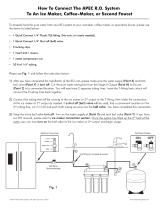
3-STAGE WATER FILTRATION SYSTEM
INSTALLATION INSTRUCTION
& OWNER’S MANUAL
Ver 1.2
All Rights Reserved © APEC Water Systems


Please keep this Owner’s Manual for future reference.
It contains useful information on how to maintain and care for your
APEC quick flow water filter system.
TABLE OF CONTENT
1. Installation:
Preparation ................................................................... page 1
Filter housings assembly ................................................. page 4
Feed water connection .................................................... page 5
Faucet mounting ............................................................ page 10
Connecting the whole system ......................................... page 11
2. Maintenance:
Filter change schedule & instructions ............................. page 14
3. Warranty ........................................................................... page 15

1
Thank you for choosing APEC drinking water systems.
You now own the finest water filter in America.
Please read and become familiar with instructions and parts needed before proceeding with
the installation.
BEFORE INSTALLATION:
Inspect the system:
Please take the system and all the components out of the box. Inspect the system and all the con-
nection fittings carefully, make sure nothing is damaged during shipping. If any part is cracked or
broken, please do not proceed with the installation and contact APEC or your distributor for an
exchange or diagnosis.
Recommended tools list:
• Variable speed drill
• Drill bit: 1/2” (for standard faucet hole, air-gap faucet requires 1&1/4” hole)
• 5/8”, 9/16” open-end wrench, or adjustable wrench, pliers
• Utility knife, or scissors
• Teflon tape
Operating Parameter
• Operating pressure: 20 psi minimum to 85psi maximum
• Feed water temperature: 40 – 100 degree F (4-37 degree C)
• Do not connect this unit to hot water source
• Install the unit in a sheltered environment, avoid exposure to hot and cold weather or under
direct sun light.
Copyright:
This manual is copyrighted by APEC Inc. Under the copyright laws, this manual may not be reproduced in any form, in
whole or part, without the prior written consent of APEC Inc.
General Installation/Operation/Maintenance Requirements
• Installation needs to comply with state and local laws and regulations.
• Do not use with water that is microbiologically unsafe or of unknown quality without ad-
equate disinfection before or after system. Systems certified for cyst reduction may be used
on disinfected water that may contain filterable cysts.
• This system contains a replaceable treatment component critical for effective reduction of
total dissolved solids. The product water shall be tested periodically to verify that system is
performing satisfactorily.

2
Components included with the system:
Make sure you have all these parts before starting installation.
3 filters in 3 Housings
Installation kit includes:
1 Faucet with
washers and nuts
2 Color tubing 1/4”
1 Wrench
for opening housing
1 system head
1 Feed water adaptor
3/8”- 1/2”
with needle valve kit

3
2. Metal compression nut fitting: (comes with 1 insert, 1 sleeve, 1 nut) Only feed water adapter-
needle valve is this type.
Fitting Types: There are 2 types of fittings provided for connecting the system
Important! Use plastic sleeve and inserts on the plastic tubing we
provide. Do Not use metal sleeve or insert on plastic tubing or the
connection will leak!
Fig.1B
How to connect: - See Fig.1B. Slide the compression nut onto the tubing.
- Slide the plastic sleeve onto the tubing.
- Insert the “insert” into the tubing.
- Insert the tubing into the opening of the fitting.
- Slide the brass nut up, then tighten nut with a wrench. No Teflon tape!
(An extra metal sleeve is provided in case you need to connect your own metal
tubing. Use Teflon tape if connecting metal tubing.)
1. Quick-Connect (QC) fitting: (no insert, sleeve, or nut)
How to Connect: - See Fig.1. Push the tubing into the Quick-Connect fitting, then gently
pull back on the tubing to make sure connection was secure.
- No inserts, sleeve, or nuts are needed to secure the connection.
- No Teflon tape!
To Disconnect: - See Fig.1A. Push in and hold down on the collet ring square against
the fitting. With the collet held in this position the tube can be removed.
Fig. 1
Fig. 1A

4
3rd
Stage
2nd
Stage
1st
Stage
Use
Wr
ench
3rd
Stage
2nd
Stage
1st
Stage
THERE ARE TWO PARTS TO INSTALLING THE SYSTEM:
Part I. Assemble the filters and housings onto the main system
Part II. Installing the system
PART I. ASSEMBLE THE FILTERS AND HOUSINGS ONTO THE MAIN SYSTEM
Remove plastic/paper wrappings on the 3 filters, put them into the 3 housings, and assemble the
housings onto the main system as follow:
1. See Fig. 2 Stand the 3 housings upright. Make sure each housing has a rubber O-ring in its
groove.
Put the APEC Sediment filter into the “1
st
stage” housing on the right.
Put the APEC Carbon filter into the “2
nd
stage” housing in the middle.
Put the APEC Carbon filter into the “3
rd
stage” housing on the left.
2. See Fig. 3 Starting from the 3
rd
stage housing on the left, hand twist the housing onto the main
system turning counterclockwise, one by one, for all 3 housings.
3. See Fig. 4 Use the wrench provided to completely tighten the housing starting from 1st-stage.
Repeat this step for the 2
nd
stage housing in the middle, and for the 3
rd
stage housing
on right.
Note: For some people it is easier to use the wrench with the system laid down
(face up).
Fig. 2
Fig. 3
Fig. 4
3rd
Stage
turn counter-clock
wise
to tighten

5
PART II. INSTALLING THE SYSTEM
Space: Make sure there is sufficient space under the counter for installation (an area of about
15”L x 6”W x 12”H for the system).
The system is best installed under the kitchen sink. But if that is not feasible you can
install the system anywhere where there is a cold water supply with sufficient water
pressure.
Mounting: No need to mount the system on the wall. The system can stand in the sink cabinet
without mounting, this makes future filter change easy and convenient. If you prefer
to mount the system to the wall, please make sure it can be taken down easily for
filter replacement.
Step 1: Feed Water Connection
The system must be connected to the COLD water supply only!
1. Locate the Cold water supply valve under the kitchen sink (the round or oblong handle on
the right side). Turn off the incoming cold water completely by turning the shut off handle
clockwise.
Note: If the cold water shut off valve can not turn off the water, the main water supply
to the house must be shut off for the installation. Another option is to use a “self
piercing saddle valve” from APEC or from a local hardware store.
2. Feed Water Adaptor (1/2” to 3/8”): See Fig. 5. The Feed Water Adaptor comes with a
separate Needle Valve. The Adaptor goes inline onto your 1/2” or 3/8” cold water pipe. The
Needle Valve portion screws onto the Adaptor as shown in Fig. 5A.
Fig. 5
A. 1/2” x 3/8” Male-Female Water Supply Adapter
with O-ring.
B. 1/2” x 3/8” Male-Female Converter with O-ring.
C. 1/4” x 1/8” Male Needle Valve.

6
Fig. 5A - Needle Valve Installation.
Attach the needle valve (C) to water supply adapter (A). Please apply 5-6 wraps of
teflon tape to needle valve prior to connecting it to the water supply adapter (A).
Fig. 5B - If your pipe has a 1/2” Connection.
By attaching the 1/2” x 3/8” converter (B) to the Male end of the water supply adapter
(A), you now have a 1/2” Male and Female water supply adapter.
Fig. 5C - If your pipe has a 3/8” Connection.
By attaching the 1/2” x 3/8” converter (B) to the Female end of the water supply
adapter (A), you now have a 3/8” Male and Female water supply adapter.
Fig. 5A
Fig. 5B
Fig. 5C

7
3. Recommend Connection For Flex Line Riser: See Fig. 6A. Loosen nut and separate cold water riser
tube from shut off valve. Gently bend riser tube so that the Feed Water Adapter (Fig 4) fits onto the shut
off valve. If your riser tube has no built-in washer, then fit the cone-shaped washer provided onto the riser
tube. Connect the riser tube, feed water adapter, and shut off valve together and tighten.
For Solid Copper Riser: See Fig. 6B. Follow the same procedure as for flex line. If the copper riser
cannot bend, this it’s best to replace it with a flex line riser. Fit the feed water adaptor to the shut off valve
the same way as described above.
Riser
Tube
Fo
r Flexible Line
Faucet
Shank
Main Water
Supply
Shut-off
Valve
Riser
Tube
For Solid Line
Faucet
Shank
Needle
Valve
Needle
Valve
Main Wate
r
Supply
Shut-off
Valve
Sink
Sink
Fig. 6A Fig. 6B

8
Test for leaks at this point: Close the Needle Valve (turn needle handle clockwise all the way
in to close). Turn ON the cold water supply to the sink faucet. If the Needle Valve or the Adap-
tor leaks, check the connection and try applying more Teflon tape or tighten the brass nut some
more to stop the leak.
Fig. 6C
Fig. 6D
4. Needle Valve: See Fig. 6C. Screw the Needle Valve onto the Adaptor tightly. Apply 6-8 rounds
of Teflon tape onto Needle Valve before attaching it to the Adaptor.
To open needle valve: Turn needle handle counter-clockwise.
To close needle valve: Turn needle handle clockwise.

9
Step 2: Drill A Hole For The Faucet
Drill 1/2” diameter hole for standard faucet. (Air-Gap faucet: drill 1&1/4” hole.)
For best results use a 1/2” carbide-tipped masonry drill bit.
Wear safety glasses to protect your eyes while drilling the faucet hole.
Note: No need to drill a hole if an existing hole is available:
a) Spare hole: If there is a spare hole in the sink covered by a chrome cover, simply remove the
chrome cover and install the faucet there.
b) Spray hose: If the spray hose is not in use, remove the hose, and mount the faucet there. Re-
member to plug up the outlet under the main faucet. If the spray hose uses a diverter at the base of
the spout, be sure to remove it to avoid trouble later on.
c) Hanging faucet: If drilling a hole is not feasible (i.e. rental home, drill tool not available etc.),
the faucet can just on the cabinet door or wherever that is convenient. Be creative!
When drilling a hole for the faucet, choose a location that looks good, works well, and is most
convenient for dispensing pure water. An ample flat area is required for the faucet base so that
the faucet can be drawn down tightly.
1. Faucet location: Make sure the faucet stud will be accessible from below when the hole
is drilled. If space is not available on the upper sink area, the faucet can be located on the
counter top by the edge of the sink. If the counter top is ceramic tile, the method for drilling
the hole will be the same as for porcelain sinks.
2. For Stainless Steel Sink: Before using a 1/2” carbide drill bit, an indent should be made
with a center punch to keep the drill bit from walking. A small pilot hole will also aid the drill
bit.
3. For Porcelain Sink: Porcelain enameled sinks can readily be chipped if care is not exercised
when drilling the hole. Before starting the drill motor, apply firm downward pressure on the bit
until a crunching occurs. This will help keep the drill bit from walking when starting the hole.
A small pilot hole will also aid the drill bit.
Note: Immediately after the hole drilling is done, clean up all metal chips, as metal chips
will stain the porcelain!!

10
Step 3: Mounting The Faucet
1. Mount the faucet as shown in Fig.7.
Step 4: Positioning The System
1. Main System: The main system can stand in the sink cabinet. No need to mount the system
to the wall.
2. Connect the White line to the faucet.
3. The faucet has two operating positions:
Push black lever down to fill a glass
of water, or lift lever up into a locked
position to fill a con tainer or to drain
the storage tank.
Fig. 7
Chrome Base
Black L
ocating Washer
Lock Washer
Lock Nut
Insert
Sleeve
Compression Nu
t
Counter Top
Counter Top
Opening
B
a
s
e

11
Step 5: Connecting The System
Summary of Tubing Connections:
There are 2 connections: See Fig 8
Point A to X: Connect system to COLD water supply — Red tubing.
Point H to Z: Connect product water from 3
rd
-stage output to faucet — White tubing.
Fig. 8

12
2. Point X Feed water connection:
Tubing color: Red tubing. Connect the RED tubing to the Feed Water Needle Valve.
Fitting type: Metal compression nut fitting. See Fig.1B on page 4. Use plastic sleeve.
Add “insert” to tubing. No teflon tape here. Tighten nut with wrench.
Tips! If Point X leaks after you have tightened the brass nut, check to make sure you did put the
plastic “insert and sleeve” onto the tubing. If the insert is already in place, then try ap-
plying Teflon tape from the threaded metal stud all the way to the plastic tubing, wrap the
whole connection with 8-10 rounds of Teflon tape. Smooth out the tape on the threaded
part with your fingers. Tighten brass nut again. This should stop the leak.
If the plastic sleeve is damaged, you can use the metal sleeve, but you need to apply
Teflon tape as described above, this should stop the leak.
Details on Tubing Connections:
To ensure a smooth and correct installation, please connect the water lines following the se-
quence and order outlined below. Refer to Fig.8 for proper point locations.
1. Point Z Faucet connection:
Tubing color: White tubing. Connect the WHITE tubing to the base of the faucet.
Fitting type: Quick Connect Fitting. Simply push White tubing into Quick Connect fitting. No Insert,
Sleeve or Nut needed here. (Attach threaded end of faucet adapter to the faucet metal
stem. No teflon tape needed here)
3. Point A System water inlet (to Stage 1 filter) connection:
Tubing color: Red tubing. Connect the RED tubing from the Feed Water Valve to stage -1
filter.
Fitting type: Quick Connect fitting See Fig.1 on page 4. Simply push the Red tubing into the Quick
Connect fitting. No Inserts, Sleeves or Nuts are needed to secure the connection. No tef-
lon tape needed here.
4. Point H Stage-3 filtered water to faucet connection:
Tubing color: White tubing. Connect the WHITE tubing from the faucet base stud to the Stage-3 filter’s
outflow end at point H.
Fitting type: Quick Connect fitting See Fig.1 on page 4. Simply push the White tubing into outlet
on the 3rd stage filter. No Inserts, Sleeves or Nuts are needed to secure the
connection. No Teflon tape needed here.

13
Ball Valve
(Recommended)
Tee tting for
icemaker
Sour
ce
Water
Refrigerator
Fig. 9
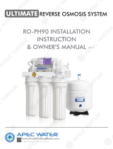
Option: Ice-maker Connection
If you want to connect product water from the System to your ice-maker, you will need:
• One T-fitting, preferably the quick-connect type fitting
• Extra ¼ “ tubing long enough to go from the system to your ice-maker
• Optional: One shut-off valve, preferably the quick-connect type.
See Fig.9. Before connecting the product water line from Point Z to H, add a T-fitting near point
H to divert product water to both the ice-maker and the faucet.
Option: Multiple Outputs - Add Shut Off Valve:
If your system is feeding several output points (icemaker, fridge, bathroom), you should add a
Shut-Off valve to each output line (except the spigot line). This way, if you ever need to diag-
nose a problem in the system, you can easily shut off these lines to isolate the water flow for ac-
curate troubleshooting.
Step 7: System Start-Up
1. Turn on feed water: Slowly, turn on your Cold water supply. Turn on the Needle Valve (turn
counter-clockwise) to allow the raw water to enter the system. Check for leaks!
2. Clean up area: Allow the system to run while cleaning up tools and work area.
3. Check for leaks! Make sure no leaking at joints, fittings, valves, and tubing connections.
4. Flush the System and new filters for up to 5 minutes before use.
Congratulations! You have successfully installed the System!

14
Fig. 10
FILTER CHANGE INSTRUCTIONS
How To Replace Stages 1, 2, 3 Filters:
1) Turn OFF cold water supply to system. Lift up faucet lever briefly to relief the built-up pressure
inside the system. This will make opening the housings easier.
2) Open housing: Have the System standing upright. Slip the plastic wrench onto the #1 housing.
Looking down from a top view, you should open the housing turning clockwise. If necessary, lay
System down on the floor to get a better leverage. If the housing is too tight, use a hammer and
tap on the wrench handle to help turn the wrench.
3) Discard 3 used filters, wash housings with mild soap, rinse off. Put 3 new filters into their respec-
tive housings: sediment filter in stage-1, carbon block filters in stages 2 & 3.
4) Close up the housings. Make sure each housing has a black O-ring in the thread groves. Use
wrench to tighten each housing.
5) Remember: Turn ON the cold water supply after finished changing filters!
6) Check for leaks!
Use
Wr
ench
3rd
Stage
2nd
Stage
1st
Stage
STEP 1
STEP 2
After taking the housing off, take out
the dirty filters and put the 3 new filters
in. Remember, Stage 2 and Stage 3 are
the same carbon filters.

15
LIMITED PRODUCT WARRANTY
Scope
APEC takes pride in selling a superb line of products, including this water filtration system (“Product”). As such, APEC expressly war-
rants to the original purchaser that, for a period of one (1) year from the date of purchase, the Product will be reasonably free of
defects in materials and workmanship. Within that one (1) year period from the original purchase, APEC will, at its option, repair or
replace the Product without charge, or refund the cost of the Product, if the Product fails or does not perform as warranted solely due
to a manufacturing defect within the warranty period, subject to the limitations and exclusions set forth in this Limited Product War-
ranty. This Limited Product Warranty only applies when the Product is used, stored, handled, fabricated and/or installed in the manner
recommended by APEC in the Installation Instruction & Owner’s Manual (“Manual”).
Repair or Replacement
Repair or replacement during this one (1) year warranty shall include reasonable labor charges necessary to repair or replace the de-
fective Product, but shall not include freight charges or any other local labor charges from third parties other than APEC, unless APEC
expressly approves such charges in writing. During the entire one (1) year warranty, APEC’s obligation to repair or replace shall further
be limited to repair or replacement with the styles, models, products, colors, etc. of the Product that are available at the time of the
repair or replacement, and shall be limited to the repair or replacement of only the specific Product that fails due to a manufacturing
defect. Any repaired or replaced product shall also remain subject to the original one (1) year warranty from the date of the original
purchase, and any repair or replacement shall not extend the original warranty period in any manner or start a new warranty period.
Conditions of Validity of this Limited Product Warranty
Even though the Product has extremely high endurance for operating conditions such as pH, maximum TDS, temperature, and opti-
mum water pressure, THIS LIMITED PRODUCT WARRANTY SHALL ONLY BE VALID IF:
1. The replaceable filters and membrane are changed and maintained on a regular basis as directed in the Manual. Moreover,
depending on local water input water quality, regular maintenance may need to be increased.
2. The Product is operated within the confines of the following standard operating conditions:
Water Pressure pH Range Water Temperature
Water Filtration System 20- 85 psi 2-11 40-100 F
Any information or suggestion by APEC with respect to the Product concerning applications, specifications or compliance with codes
and standards is provided solely for your convenient reference and is made without any representation as to accuracy or suitability. You
must verify and test the suitability of any information with respect to the Product for your specific application.
Non-Covered Defects
THIS LIMITED PRODUCT WARRANTY DOES NOT COVER DEFECTS CAUSED BY:
1. Improper storage, installation, maintenance, handling, use and/or alterations of the Product, including, but not limited to, non-
compliance with the installation, maintenance and standard operation conditions stated in the Manual and this Limited Product
Warranty.
2. Unreasonable use, unintended use, or misuse of the Product for something other than its intended purpose as a reverse osmosis
system.
3. Use of replacement parts, filters, membranes or other accessories that are not sold or manufactured by APEC for use with this
particular Product.
4. Damage not resulting from manufacturing defects that occur while the Product is in the original purchaser’s possession.
5. Installation of the Product with known or visible manufacturing defects at the time of installation.
6. Damage caused by freezing, flood, fire or Act of God.

16
CONDITIONS THAT RENDER THIS LIMITED PRODUCT WARRANTY VOID
THIS LIMITED PRODUCT WARRANTY SHALL BE VOID IF:
1. The Product is not operated in compliance with normal municipal water conditions for which the particular model of this Product
is intended.
2. The person seeking to invoke the warranty is not the original purchaser. That is, this Limited Product Warranty only extends to
original purchasers.
3. The is purchased used. That is, this Limited Product Warranty only covers new products.
4. The Product is purchased from someone other than APEC or one of APEC’s authorized dealers. This is because, unless the
Product was sold by APEC or one of its authorized dealers, APEC cannot verify or guarantee the integrity or authenticity of the
Product.
General Conditions
The warranties set forth herein are the only warranties made by APEC in connection with the product. APEC cannot and
does not make any implied or express warranties with respect to the product, and disclaims all other warranties, includ-
ing, but not limited to, any warranty of merchantability or fitness for a particular purpose. Products sold by APEC are
sold only to the specifications specifically set forth by APEC in writing. Other than the limited product warranty set forth
herein, APEC makes no other warranties, express or implied. APEC’s sole obligation under this warranty shall be repair
or replacement of a non-conforming product or parts of the product, or at the option of APEC, return of the product and
a refund of the purchase price. Buyer assumes all risk whatsoever as to the result of the use of the product purchased,
whether used singularly or in combination with any other products or substances.
No claim by the buyer/owner of any kind, including claims for indemnification, shall be greater in amount than the
purchase price of the products in respect to which damages are claimed. In no event shall APEC be liable to buyer/owner
in tort, contract or otherwise, for any special, indirect, incidental, consequential, reliance, statutory, special, punitive or
exemplary damages, including, but not limited to, lost profits, loss of use, loss of time, inconvenience, damage to good
will or reputation, or loss of data, even if advised of the possibility of such damages or such damages could have been
reasonably foreseen, in connection with, arising out of, or as a result of, the sale, delivery, servicing, use or loss of use of
the products sold hereunder, or for any liability of buyer to any third party with respect thereto.
Obtaining Warranty Coverage or General Inquiries
If coverage is available, you may obtain coverage under this Limited Product Warranty by providing APEC with proof of original
purchase, and that you are the original purchaser. For service under this Limited Product Warranty, you must notify APEC by phone at
1-800-880-4808, by email at techsupport@freedrinkingwater.com, or in writing at 1320 S. Johnson Dr., City of Industry, CA 91745.
In making the claim, please provide your name, address, phone number, a description of the product involved, and an explanation of
the defect.

17
Advanced Purification Engineering Corp.
1320 S Johnson Drive
City of Industry, CA 91745
For questions or comments please visit our website at:
FreeDrinkingWater.com
For technical support contact us at:
Techsupport@freedrinkingwater.com
1-800-880-4808
/