Honeywell CM921 User manual

Category
Thermostats
Type
User manual

This manual is also suitable for

CM900 Wireless
Installation Guide
CM927 / CM921 Wireless Programmable
Room Thermostat & BDR91 Relay Box
Description
The Honeywell CM900 Wireless (CM927 or
CM921) is a modern wireless programmable
room thermostat based on Honeywell’s proven
programming philosophy. To further improve the
ease of use, this product includes an extra large
LCD display with backlighting and LoT Technology
to assist customers during daily use.
The CM927/921 room thermostat communicates
with the BDR91 Relay Box on an 868MHz Radio
Frequency (RF) band to control a single heating
system component such as a boiler, pump or
zone valve. Neither product will communicate with
other RF products that use different frequencies or
communication protocols.
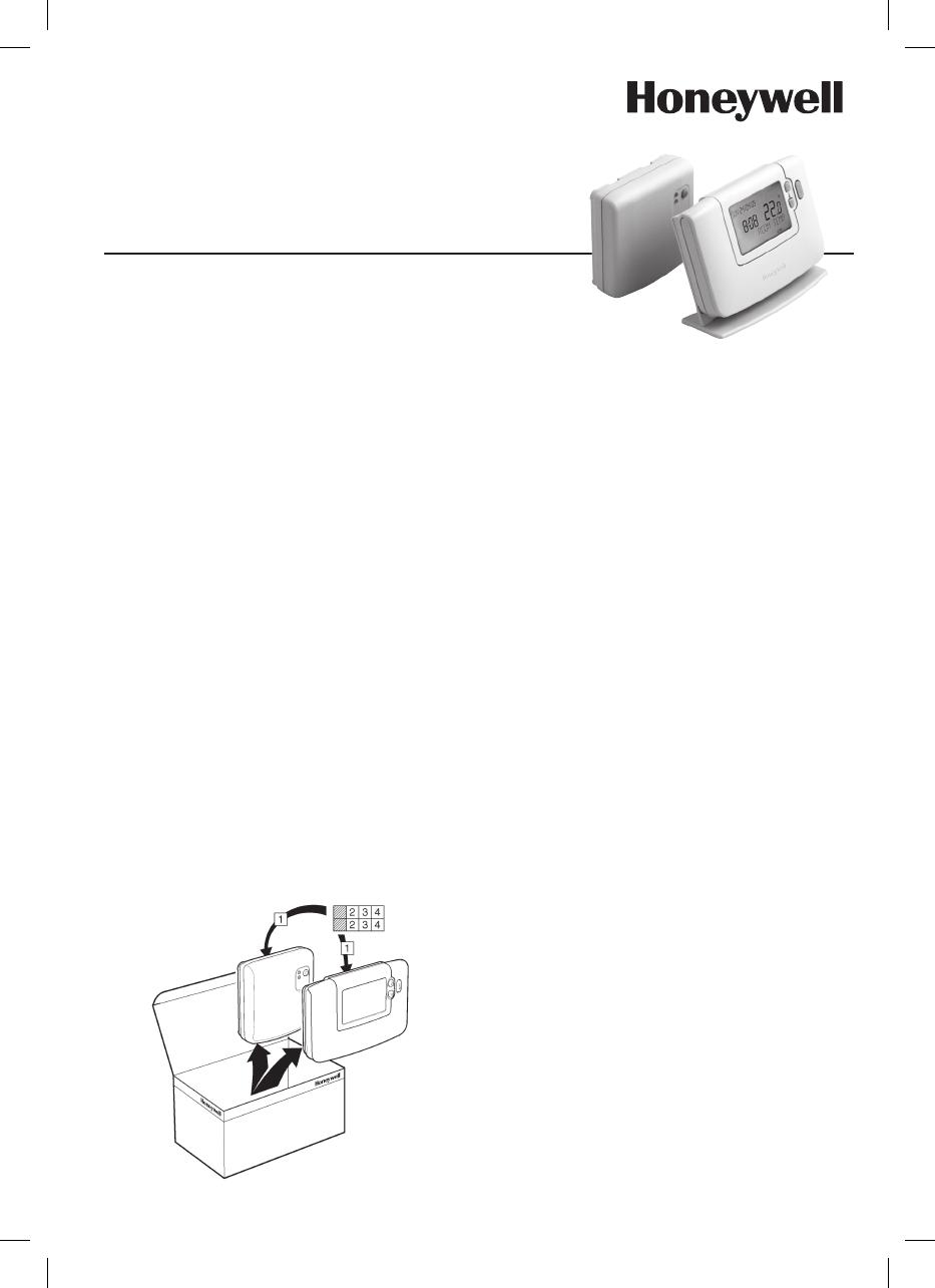
Note: The RF link between the individual room
thermostat (CM927/921) and Relay Box (BDR91)
in system packs provided by Honeywell is pre-
configured at the factory and therefore SHOULD
be installed at the same site. This makes the
installation process fast and easy, but if products
from individual system packs are separated, or
mixed with other pre-configured system packs
during installations please refer to section 5.1
Binding / Rebinding Procedure to bind the desired
units together and allow them to communicate with
each other.
Table of Contents
Section Page
1) Installation Information ................................. 2
2) Installing the CM900 Wireless System ......... 3
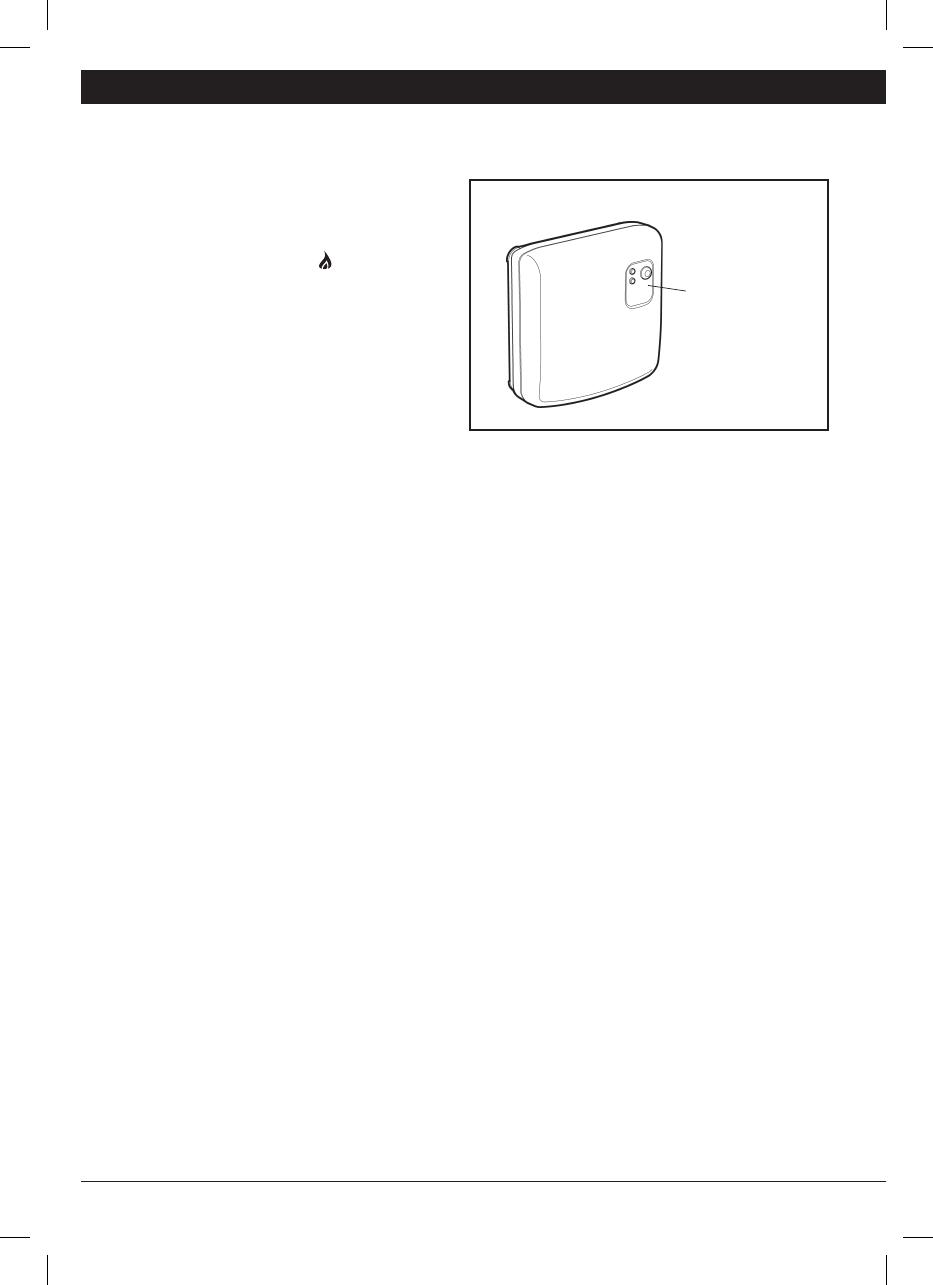
2.1 Installing the Relay Box ................................... 3
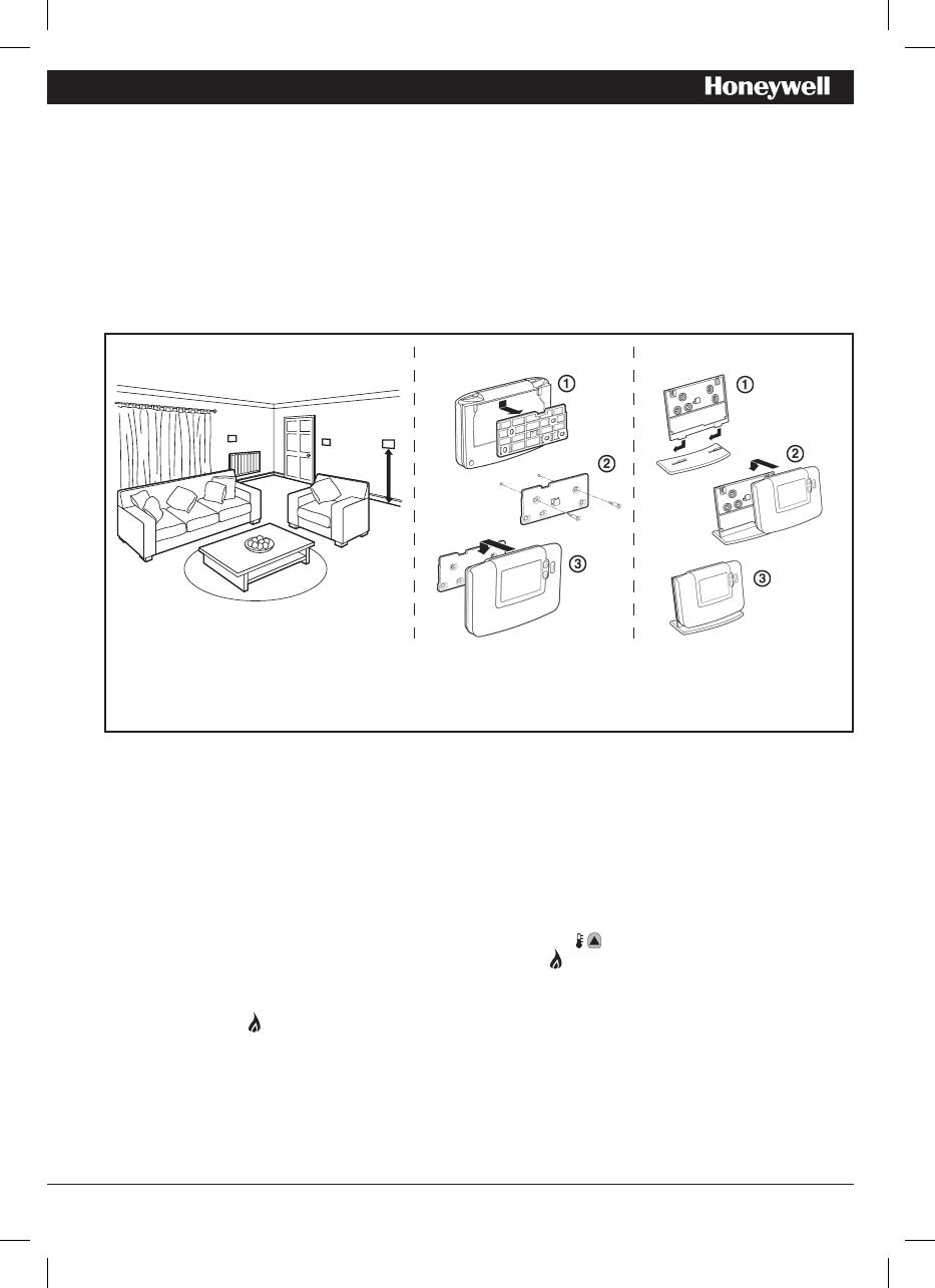
2.2 Installing the Room Thermostat ........................ 4
2.2.1 Power Up ............................................... 4
2.2.2 RF Communication Check ........................ 4
2.2.3 Locating the Room Thermostat ................. 5
2.3 System Check................................................ 5
3) Basic Operation of the System ..................... 6
3.1 Automatic Operation ....................................... 6
3.2 Temporary Manual Override ............................. 6
3.3 Communication Loss ...................................... 6
4) Installer Mode ................................................. 6
4.1 Entering Installer Mode ................................... 7
4.2 BDR91 Relay Box Fail-Safe Mode Setup ............ 7
4.3 Using the Room Thermostat for Specific Applications
.. 8
4.4 Using the Special Features of the Room Thermostat
.. 8
4.5 Installer Parameters Table ............................... 9
4.5.1 Category 1 - Room Thermostat Settings ..... 9
4.5.2 Category 2 - System Settings .................. 10
5) Additional Installation Information ............. 11
5.1 Binding / Rebinding Procedure ...................... 11
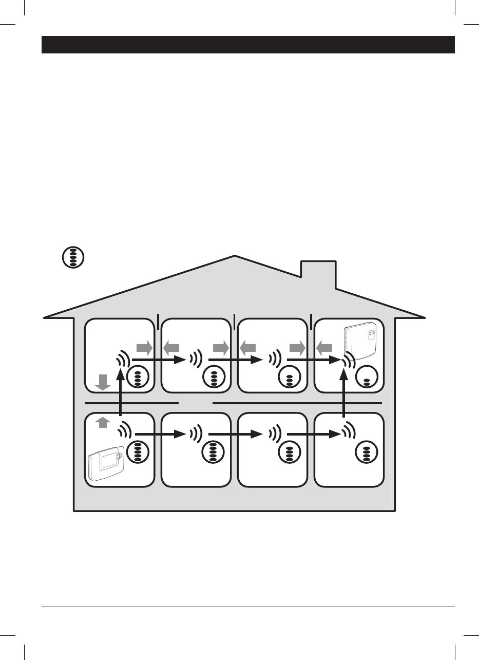
5.2 Multi-Zone System ........................................ 11
5.3 Binding an HR80 Radiator Controller
to the Room Thermostat ................................ 11
6) Trouble Shooting .......................................... 12
6.1 Trouble Shooting Guide ................................. 12
6.2 Diagnostics Mode ........................................ 12
50039987-003 A
2 CM900 Wireless - Programmable Room Thermostat
1) Installation Information
As these products communicate using RF technology special care must be taken during installation. The
location of the RF components as well as the building structure may influence performance of the RF
system. To assure system reliability, please review and apply the information given below.
Within a typical residential building the two products should communicate reliably within a 30m range. It
is important to take into consideration that walls and ceilings will reduce the RF signal. The strength of
the RF signal reaching the Relay Box depends on the number of walls and ceilings separating it from the
room thermostat, as well as the building construction - the diagram below illustrates an example of typical
signal strength reduction. Walls and ceilings reinforced with steel or plasterboard walls lined with metal foil
reduce the RF signal significantly more.
Once a position is selected for the room thermostat this can be checked using the RF Communication Test
mode as described in section 2.2.3 Locating the Room Thermostat. If the position is unsuitable the Relay
Box will not respond and an alternative position must be selected.
Typical example of Building Fabric Signal losses
Wall Wall Wall
Ceiling
Max. Signal Length 30 metres
= Signal Strength
Installation Guide 3
2) Installing the CM900 Wireless System
Please follow the illustrations and information below in sequence to install the Relay Box and room
thermostat correctly. For applications other than gas boilers, enabling special features and to see what
other system options are available refer to section 4) Installer Mode.
2.1 Installing the Relay Box
1
The Relay Box is a RF device. For the
best performance install in an open
space. Leave at least 30cm distance
from any metal objects including wall
boxes and boiler housing.
Do not mount on metal wall boxes.
EMC compliance considerations
Keep AC mains supply/load cables
separate from signal wiring.
Refer to Code of Practice standards
EN61000-5-1 and -2 for guidance.
NOTE: The Relay Box contains
no user serviceable parts. It
should be opened and installed
by qualified installer only.
WARNING: Electrostatic sensi-
tive device! Do not touch the
circuit board.
NOTE: All wiring must be in accordance with IEE regulations
CAUTION: Observe ambient temperature and current limits
(see the Relay Box wiring label)
Burner (direct control)
Zone valve Cooling device
2 3
4
< 7mm Ø
> 7mm Ø
a.
b.
6
5
1.5-2.5mm²
6mm max.
Combi boiler
230V
50-60Hz
<
5A
BDR91
A-B:5(3)A
A-C:5(3)A
BDR91
A-B:5(3)A
A-C:5(3)A
230V
50-60Hz
<
5A
V4043H
BDR91
A-B:5(3)A
A-C:5(3)A
230V
50-60Hz
<
5A
BDR91
A-B:5(3)A
A-C:5(3)A
230V
50-60Hz
<
5A
= M3.5
=
N
o
6
1
2
2
1
4 CM900 Wireless - Programmable Room Thermostat
2.2 Installing the Room Thermostat
2.2.1 Power Up
1. Remove the battery cover and insert the batteries supplied with the room thermostat (2 x AA LR6
Alkaline Batteries).
2.
On the initial power up the available user interface languages will be displayed (only on certain models).
Use the
or
buttons to cycle through the options until the desired language is displayed. Press the
green button to confirm the selection.
3. Set the slider switch to the DATE mode.
4.
Use the or buttons to set the correct day / month / year, pressing the green button to
confirm.
5.
Use the or buttons to set the correct time, pressing the green button to confirm.
2.2.2 RF Communication Check (Test Mode)
To check the RF communication, hold the room thermostat about 2-3 metres from the installed Relay Box.
Move the slider on the room thermostat to the OFF position then press the and buttons together
with the button for 3 seconds. The unit will display ‘TEST TRANSMITand it will send test signals to the
Relay Box, flashing the green LED on every 6 seconds (relay output will remain off) for a maximum of 10
minutes. When the green LED flashes on every 6 seconds proceed to the next step.
NOTE: If the green LED is not switched at specified intervals, the red LED is flashing or if you are installing
a replacement Relay Box or room thermostat, follow the procedures described in section 5.1 Binding /
Rebinding Procedure.
Install the batteries (included) and attach the instruction label to flap
Installation Guide 5
2.2.3 Locating the Room Thermostat
While still in the Test Mode, as described in section 2.2.2, the room thermostat should be located taking
the following into consideration and reviewing the illustrations below:
1.
Find a suitable location where the signal transmission is reliable. Reliable transmission is indicated when
the Relay Box is flashing the green LED every 6 seconds. NOTE: The Relay Box relay will be off.
2. Install the room thermostat EITHER on the wall using the wall bracket OR attach the optional table stand
as shown in below.
3.
Exit the Test Mode by moving the setting slider to the required operating mode (AUTO or OFF).
2.3 System Check
Now a simple test can be completed to check the full system has been installed correctly:
1.
Set the slider switch to the OFF mode.
2.
Check the boiler supply is on and check that the green LED on the Relay Box is off.
3. Set the slider switch to the MAN mode.
4.
Adjust the setpoint up to the maximum (35°C) by pressing the button. The boiler should come on
(green LED ON on Relay Box) after a few seconds and the symbol appears on the room thermostat
LCD display.
5. Set the slider switch to the OFF mode. The boiler will go off (green LED OFF on Relay Box) after a few
seconds and the symbol disappears.
6.
Check the system operation by moving the slider between MAN and OFF modes several times, bearing
in mind the switching delay referred to above.
Now, you should have completed the installation successfully - to begin operating at the default factory
settings move the slider to the AUTO mode or select PROG to modify the built-in heating program
accordingly.
Wall bracket Table stand
•Theroomthermostatshouldbeinstalledinanopenspaceforbestperformanceasitisaradiofrequencydevice.
•
Leave at least 30cm distance from any metal objects including wall boxes and at least 1 metre from any other
electrical equipment eg. radio, TV, PC etc.
•Donotmountontometalwallboxes.•ItisrecommendedthattheRelayBoxisfullyinstalled.
1.2m
6 CM900 Wireless - Programmable Room Thermostat
3.1 Automatic Operation
The Relay Box receives the heat demand (0-
100%) signal from the room thermostat. The
room thermostat will display the symbol on the
LCD display whenever more heat is required.
Depending on the demand the Relay Box will
switch the heating device on to match the current
requirements of the system.
The green LED indicates the status of the relay
output:
• GreenLEDon=relayon
• GreenLEDoff=relayoff
3.2 Temporary Manual Override
Pressing the Relay Box button will override the current relay position. As soon as the next signal is received
from the room thermostat the Relay Box will return back to automatic operation as the automatic control
has higher priority than manual operation.
3.3 Communications Loss
If the RF communication is lost for a period of 1 hour the red LED will illuminate to indicate that no RF
messages have been received during the last hour.
The Relay Box will also enter the failsafe mode as selected in Installer Mode (see section 4.2 BDR91
Relay Box Fail-Safe Mode Setup). To allow manual control of the Relay Box output manual override is
available in fail-safe mode. When RF communication is restored the Relay Box will automatically return to
normal operation.
You can now use the USER GUIDE supplied with the room thermostat to demonstrate how it works to the
home owner.
3) Basic Operation of the System
4) Installer Mode
Installer Mode is used to alter the system settings for specific applications, to use the special features of
the room thermostat in a different way or to alter the factory preset parameters. Parameters are divided
into two groups:
- Category 1 parameters – Room Thermostat Setup
- Category 2 parameters – System Setup.
These are all listed in section 4.5 Installer Parameters Table.
BDR91 Relay Box
Push button and
relay status LED’s
Installation Guide 7
4.1 Entering Installer Mode
4.2 BDR91 Relay Box Fail-Safe Mode Setup
The failsafe mode defines the Relay Box output relay status if the RF communication is lost (e.g. when
the room thermostat stops communicating due to discharged batteries). The factory setting keeps the
relay permanently off when communications is lost. If this factory setting needs to be changed follow the
instructions below:
1.
Enter Installer mode as described above.
2. Press the button to enter category 2 parameters.
3. Select the parameter 7:LC by pressing the button.
4. Select the fail-safe mode by pressing or buttons:
• 0-whenRFcommunicationislosttherelaywillbeheldinOFF position.
• 1-whenRFcommunicationislosttherelayoutputwillcycleat20%on80%off.
5. Press the green button to accept the change.
6.
Attach appropriate label to the Relay Box to indicate the selected fail-safe mode.
IMPORTANT: To enable the frost protection when RF communication is lost, select the fail-safe mode 1. For
systems with separate frost protection thermostat or where frost protection is not required select fail-safe
mode 0.
Move the slider switch to the OFF mode.
Press and hold the
button and the two &
buttons together.
Press the
or to
change factory setting.
The display will flash
indicating that a change
has been made.
Press the green
button to confirm the
change.
The display will stop
flashing.
Press
button to go to Installer parameter group
category 2 ( ) (from Parameter n.1 to n.14).
To exit the installer mode, move the slider switch to
the AUTO or MAN positions.
Press
button to go
to the next parameter.
The unit will display the first parameter of installer
parameter group category 1 (from Parameter n.1
to n.19) as shown
1 2
3 4
5 6
7
COPY
D A Y
D A Y
1..6
C M 9 2 7
D A T E
PROG
A U T O
MAN
OFF
OFF
8 CM900 Wireless - Programmable Room Thermostat
4.3 Using the Room Thermostat for Specific Applications
The CM927/921 RF room thermostat is a versatile controller that can be used to control many different
applications. For most typical applications, like wall-hung gas fired combination boiler control or zone
valve control, no adjustments from the factory settings are required. For other applications, like controlling
an oil burner, the best system performance can be achieved by modifying selected parameters of the
room thermostat in the Installer mode. The table below lists the most common settings used for specific
applications.
4.4 Using the Special Features of the Room Thermostat
Special Feature: Description: Enable/Disable
Optimisation
(Variable Start
Time)
The thermostat will adjust the start time in the morning/afternoon so the
desired temperature is reached by the start of the program period. The
system will restrict the start time to a max of 2 hours.
To enable: Set parameter 8:
OP (category 1) to 1.
Heating or Cooling
Operation
This product can be used for heating or cooling applications. If you select
cooling mode the control algorithm and factory default program will be
modified. You can independently modify the heating and cooling profile.
To enable: Set parameter 4:
HC (category 2) to 1.
Summer/Winter
Auto time change
This feature moves time automatically on the last Sunday of March and
the last Sunday of October. The feature is factory enabled.
To enable: Set parameter 3:
tC (category 1) to 1.
Temperature Offset If the thermostat is located in a particularly hot/cold location for reliable
signal transmission reasons then the measured/displayed temperature
can be adjusted by +/- 3°C. This is useful if the homeowner wants the
reading to match another appliance temperature display.
Set parameter 12:tO
(category 1) to the required
offset value.
Upper/Lower
Temperature Limit
The normal upper temperature limit of 35°C can be reduced to 21°C
to save the homeowner energy. The normal lower limit of 5°C can be
increased up to 21°C to protect inhabitants from cold.
Set parameter 6:uL (category
1) to the desired upper limit.
Set parameter 7:LL (category
1) to the desired lower limit.
Specific Application: Setting: What to change:
Cycle/
Hour
Minimum ON
Time
Note: All parameters listed below belong to category 2
- System Parameters (see Installer Parameters Table)
HEATING
Gas Boiler (<30kW) 6 1 No changes required
Oil Boiler 3 4 Set 1:Ot parameter to 4
Set 2:Cr parameter to 3
Thermal Actuator 12 1 Set 2:Cr parameter to 12
Zone Valve 6 1 No changes required
AIR-
CONDITIONING
To enable switching between cooling and heating
modesadjustparameter4:HCincategory2(0=
disabled,1=enabled).Nowyoucanswitchbetween
these modes by pressing the and buttons
together for 5 seconds in any of the product operating
modes (AUTO, MAN or OFF). Explain to the end user
how to switch between these modes using the
and
buttons and ensure the cooling program is modified
as required.
Heat Pump / Air-
Conditioner
3 4 Set 1:Ot parameter to 4
Set 2:Cr parameter to 3
Fan Coil 6 1 No changes required
Installation Guide 9
4.5 Installer Parameters Table
4.5.1 Category 1 - Room Thermostat Settings
Notes
1) Remember to always press the green button to confirm that you want to store your new Installer Set-
Up setting. To exit the Installer Mode move the slider switch to the AUTO or MAN position.
Parameter Parameter
No.
Factory Default Setting Optional Setting
Category 1 Parameters – Room Thermostat Settings
Display Description Display Description
AM-PM / 24hr
Display
1:CL 24 24 hr clock display
format
12 12 hr – AM/PM clock display format
Reset Time/ Temp
Program
2:rP 1 Time / Temp profile set
to factory default
Changes to 0 when
one of the time/temp
profiles are changed
0 Time / Temperature are as programmed
To restore the factory profile set to 1
Auto Summer/
Winter Time
Change
3:tC 1 Auto Summer/Winter
Time Change Enabled
0 Auto Summer/Winter Time Change
Disabled
LCD Backlighting 5:bL 1 Backlighting Enable 0 Backlighting Disabled
Upper Temp Limit 6:uL 35 35°C Upper Temp.
Limit
21 to
34
21°C to 34°C adjustment in 1°C steps
Lower Temp Limit 7:LL 5 5°C Lower Temp. Limit 5 to 21 6°C to 21°C adjustment in 1°C steps
Optimisation 8:OP 0 Optimisation Disabled 1 Optimisation Enabled
Temperature Offset 12:tO 0 No temperature offset -3 to
+3
-3°C to +3°C adjustment in 0.1°C steps
Proportional Band
Width
13:Pb 1.5 Proportional band of
1.5 degrees
1.6 to
3.0
1.6°C to 3.0°C adjustment in 0.1°C steps
Reset Parameters
to Factory Defaults
19:FS 1 All settings at factory
defaults
Changes to 0 when
one of the parameter
is changed
0 Settings are as modified above
To restore the factory profile set to 1
10 CM900 Wireless - Programmable Room Thermostat
4.5.2 Category 2 - System Settings
Notes
1) Remember to always press the green button to confirm that you want to store your new Installer Set-
Up setting. To exit the Installer Mode move the slider switch to the AUTO or MAN position.
2) These parameters are set centrally for the zoning system at the room thermostat configured as the
system synchroniser.
3) Minimum on-time setting applies only to the boiler controller. All Relay Box zone controllers will work
with the minimum on-time of 30 seconds.
Parameter Parameter
No.
Factory Default Setting Optional Setting
Category 2 Parameters – System Settings (press the button to access this category)
Display Description Display Description
Minimum boiler
ON time
1:Ot 1 1 minute minimum
ON time
2 to 5 Selection of 2, 3, 4 or 5 minutes
minimum ON time
Cycle Rate 2:Cr 6 6 cycles per hour
(cph)
3,9 or
12
Selection of 3, 9 or 12 cph
Heat/Cool Change 4:HC 0 Disabled 1 Enabled
Pump Exercise 5:PE 0 Pump exercise
disabled
1 Pump exercise enabled
System
Synchronisation
6:Sn 0 Standard operation of
the Room Unit
1 Room unit configured as Synchroniser
Loss of
Communications
Instruction
7:LC 0 Relay Off 1 Relay 20% on / 80% off
The following Parameters are for the control of other Honeywell Wireless products such as Wireless Underfloor Heating
controls and Wireless Radiator controls. For more information please contact Honeywell sales.
Room Temperature
Sensor Use
8:Su 0 BDR91 control 1,2,3
or 4
1 - HR80/HM80 control with own/remote
sensor (no temperature displayed)
2 - HR80/HM80/HCE80 control with CM
sensor
3 - BDR91 control and HR80/HM80/
HCE80 control with own/remote sensor
4 – Hr80/HM80/HCE80 control with own/
remote sensor (temperature displayed)
HR80 Window-
Open Function
9:HO 0 Disabled 1 Enabled
HR80 Local
Override
10:HL 1 Enabled 0 Disabled
Maximum Flow
Setpoint
11:uF 55 55°C Maximum Flow
Temp.
0 to 99 0°C to 99°C adjustment in 1°C steps
Minimum Flow
Setpoint
12:LF 15 15°C Minimum Flow
Temp.
0 to 50 0°C to 50°C adjustment in 1°C steps
Mixing Value Run
Time
13:Ar 150 150 seconds 0 to
240
0 to 240 sec. adjustment in 1sec steps
Pump Overrun Run
Time
14:Pr 15 15 minutes 0 to 99 0 to 99 mins adjustment in 1min steps
Installation Guide 11
5) Additional Installation Information
5.1 Binding / Rebinding Procedure
The binding operation described below is required if:
• Anyofthesystemcomponents(roomthermostatorRelayBox)arereplaced.
• TheRelayBoxhasincorrectornobindingdatastored(e.g.whenpre-boundsystempackcomponents
have been mismatched).
NOTE: During the binding procedure keep approximately 1m distance between the room thermostat and
the Relay Box.
To bind/rebind:
1.
Press and hold the Relay Box push button for 15 seconds to reset any previously stored data. After 15
seconds the red LED will change to flashing 0.1sec on/0.9sec off.
NOTE: After 5 seconds the red LED will start to flash 0.5sec on/0.5sec off, but continue to hold the button).
2. Release the push button.
3. Press and hold the Relay Box push button for 5 seconds to enter the binding mode. The Red LED will
start flashing at 0.5sec on/0.5sec off to confirm the binding mode has been entered.
4. Move the room thermostat slider to the OFF position and press the and buttons together along
with the button. The unit will display InSt and ‘CONTROL BINDING’.
5.
Press the green button to send the binding signal out to the Relay Box. The red LED is switched off to confirm
successful binding operation. If the red LED still flashes push the button again until binding is successful.
6. Now go to Section 2) Installing the CM900 Wireless System to setup the system.
5.2 Multi-Zone System
Multiple room thermostats and Relay Box sets can also be used to control multi-zone systems and the
CM927/921 room thermostat is compatible with a variety of other Honeywell products including HR80 radiator
controllers (see below) and HCE80 underfloor heating controllers. If you intend to use it in this way additional
installation and user instructions can be obtained by contacting the address at the end of this guide.
NOTE: Some of the labels supplied with the pack are for use in multi-zone applications.
5.3 Binding an HR80 Radiator Controller to the Room Thermostat
1.
Press the bind button (1) for approximately one second and release. When the
button is released, the symbol flashes and the software version number is
displayed for 30 seconds.
2.
Move the room thermostat slider to the OFF position and press the and buttons
together along with the button. The unit will display InSt and ‘CONTROL BINDING’.
3. Press the green button to send the binding signal out to the radiator controller.
4. The radiator controller will display once the signal has been received.
If several radiator controllers are to be controlled simultaneously in one room:
1.
Press the bind button on all the radiator controllers to be bound to the room
thermostat. The symbol flashes continuously on the display of the radiator controller.
2.
Move the room thermostat slider to the OFF position and press the and buttons together along
with the button. The unit will display InSt and ‘CONTROL BINDING’.
3. Press the green button to send the binding signal out to the radiator controllers.
4.
The radiator controllers will display once the signal has been received. The set temperature at the
radiator controller is automatically set to 20°C.
NOTE: The radiator controller can take up to 4 minutes to receive data from the room thermostat.
1
6) Trouble Shooting
6.1 Trouble Shooting Guide
50039987-003 A
© 2009 Honeywell International Inc.
Manufactured for and on behalf of the Environmental and Combustion Controls Division of Honeywell Technologies Sàrl, ACS-ECC
EMEA, Z.A. La Pièce 16, 1180 Rolle, Switzerland by its Authorised Representative Honeywell International Inc.
Honeywell Control Systems Ltd.
Arlington Business Park,
Bracknell, Berkshire
RG12 1EB
Technical Help Desk: 08457 678999
www.honeywelluk.com
Symptom (Fault
Message)
Possible Cause Remedy
The room thermostat
displays the
symbol but
the Relay Box relay does
not switch on.
This is normal operation. The Relay Box cycles
the relay on and off for times proportional to
the demand signal (0-100%) from the room
thermostat. The
symbol only indicates that the
demand value is greater than 0%.
Using the
button change the
temperature setpoint by a few degrees.
The Relay Box should switch the relay on
after a few seconds delay.
The Relay Box does not
react to setpoint changes
on the room thermostat.
The room thermostat and Relay Box are not
bound.
Reset the Relay Box by pressing and
holding the push button for 15 seconds.
Then follow the binding / rebinding
procedure as described in section 5)
Additional Installation Information.
After the binding procedure
the red LED is on and the
green one is flashing once
every 3 sec on the Relay
Box.
Incorrect or incomplete binding procedure.
Incorrect position of the room thermostat during
binding.
Repeat the binding procedure.
Repeat the binding procedure keeping
approx. 1 m distance between the Relay
Box and the room thermostat.
The red LED on the
Relay Box is illuminated
(Communication loss)
The Relay Box receives no RF messages from
the room thermostat:
RF signal is blocked due to wrong location of the
room thermostat.
Room thermostat batteries are exhausted.
Re-locate the room thermostat following
instructions in section 2) Installing the
CM900 Wireless System.
Replace batteries in the room thermostat.
6.2 Diagnostic Mode
The CM927/921 room thermostat has a user accessible mode that provides information useful to a remote
service person and a means of checking whether the boiler is working. To access this move the slider
switch to the OFF position then press and hold the button for 5 seconds. The room thermostat will enter
the user settings mode. Next press and hold the and buttons together. The room thermostat will hold
the relay on for 5 minutes and the following information can be viewed on the display by pressing the
or buttons. : model ID, date code (WW/YY) & checksum.
Hereby, Honeywell declares that this CM927/CM921 room thermostat and BDR91 Relay Box are in
compliance with the essential requirements and other relevant provisions of Directive 1999/5/EC, 2006/95/EC
and 2004/108/EC.
®
  • Page 1 1
  • Page 2 2
  • Page 3 3
  • Page 4 4
  • Page 5 5
  • Page 6 6
  • Page 7 7
  • Page 8 8
  • Page 9 9
  • Page 10 10
  • Page 11 11
  • Page 12 12

Honeywell CM921 User manual

Category
Thermostats
Type
User manual
This manual is also suitable for

Ask a question and I''ll find the answer in the document

Finding information in a document is now easier with AI