Pro FPP12216 Installation guide
- Category
- Thermostats
- Type
- Installation guide
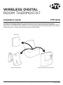
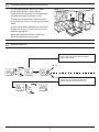
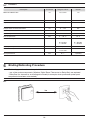
Pro FPP12216 is a wireless digital room thermostat that allows for precise temperature control in your home. It features two-way RF communication, allowing for high-performance energy-efficient control, display of boiler information, and easy setup and communication checks. The thermostat requires no power source other than the batteries provided and can be mounted on a wall or an optional table stand. It also has a temporary manual override function and a failsafe mode in case of RF communication loss.
Pro FPP12216 is a wireless digital room thermostat that allows for precise temperature control in your home. It features two-way RF communication, allowing for high-performance energy-efficient control, display of boiler information, and easy setup and communication checks. The thermostat requires no power source other than the batteries provided and can be mounted on a wall or an optional table stand. It also has a temporary manual override function and a failsafe mode in case of RF communication loss.


-
 1
1
-
 2
2
-
 3
3
-
 4
4
-
 5
5
-
 6
6
-
 7
7
-
 8
8
-
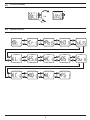 9
9
-
 10
10
-
 11
11
-
 12
12


Pro FPP12216 Installation guide
- Category
- Thermostats
- Type
- Installation guide
Pro FPP12216 is a wireless digital room thermostat that allows for precise temperature control in your home. It features two-way RF communication, allowing for high-performance energy-efficient control, display of boiler information, and easy setup and communication checks. The thermostat requires no power source other than the batteries provided and can be mounted on a wall or an optional table stand. It also has a temporary manual override function and a failsafe mode in case of RF communication loss.
Ask a question and I''ll find the answer in the document
Finding information in a document is now easier with AI
Other documents
-
Honeywell ST9520C Installation Instructions Manual
-
Honeywell BDR 91 Owner's manual
-
plumbarena FPP15206 User guide
-
-
Honeywell CM900 User manual
-
Hitachi ATW-RTU-04 Operating instructions
-
Honeywell evohome Installation guide
-
ACV RC300 (Evohome) Installation guide
-
-
Fujitsu ABYA018GTEH Installation guide