Page is loading ...

INSTALLATION INSTRUCTIONS FOR PART 95-7895
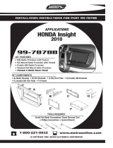
95-7895
KIT FEATURES
• DDIN Head Unit Provision
• ISO Stacked Head Unit Provision
A) Double DIN Brackets B) Double DIN Trim Plate
KIT COMPONENTS
• Small Flat Blade Screwdriver • Panel Removal Tool
• Phillips Screwdriver
1-800-221-0932
© COPYRIGHT 2007-2009 METRA ELECTRONICS CORPORATION
www.metraonline.com
TOOLS REQUIRED:
APPLICATIONS
Honda Accord
1998 - 2002
WIRING AND ANTENNA CONNECTIONS (Sold Separately)
Harness:
• 70-1721 - Honda Harness 1998-up
A
B

Dash Disassembly
- Honda Accord 1998 - 2002.........................................1
Kit
Assembly
- DDIN / Stacked ISO DIN Head Unit Provisions . . . . . . . . . . . . . . . . . . . . . . . . 2
TABLE OF CONTENTS
95-7895
*Note:
Ref
er also to the instructions included with the aftermarket radio.
K
NOWLEDGE IS
P
OWER
Enhance your installation and fabrication skills by
enrolling in the most recognized and respected
mobile electronics school in our industry.
Log onto www.installerinstitute.com or call
800-354-6782 for more information and take steps
toward a better tomorrow.
Metra recommends MECP certified
technicians.

95-7895 DASH DISASSEMBLY
HONDA ACCORD 1998 - 2002
1
Disconnect the negative battery ter-
minal to prevent an accidental short
circuit.
1
Unsnap the clock panel, disconnect
the wiring and remove.
(Figure A)
2
Remove (1) Phillips screw exposed in
the clock cavity.
(Figure A)
3
Remove (2) Phillips screws below the
factory head unit.
(Figure A)
4
Unclip the radio trim bezel and dis-
connect the wiring.
5
Remove (4) Phillips screws securing
the factory head unit assembly and
disconnect the wiring.
6
Continue to kit assembly.
A

2
95-7895 KIT ASSEMBLY
B
A
DOUBLE DIN / STACKED ISO DIN HEAD UNIT
PROVISIONS
Slide the Double DIN head unit or
stacked ISO head units into the
bracket/trim plate assembly and
secure the Double DIN head unit or
stacked ISO head units to the
assembly using the screws supplied
with the radio. (Figure B)
2
Locate the factory wiring harness in
the dash. Metra recommends using
the proper mating adapter from
Metra or AXXESS. Re-connect the
negative battery terminal and test
the unit for proper operation.
3
Reassemble dash in reverse order of
disassembly.
4
*Note: Refer also to the instructions included with the aftermarket radio.
Attach the Double DIN brackets to the
edge of the Double DIN trim plate.
(Figure A)
1

95-7895 INSTRUCTIONS
NOTES
3

95-7895 INSTRUCTIONS
NOTES
4

95-7895 INSTRUCTIONS
NOTES
5

06
INSTRUCTIONS
1-800-221-0932
REV. 11/09/09 © COPYRIGHT 2003-2009 METRA ELECTRONICS CORPORATION INST95-7895
www.metraonline.com
95-7895 INSTRUCTIONS
/