Robe Robin Spiider TW User manual
- Category
- Stroboscopes & disco lights
- Type
- User manual

1
Version 1.2

2
Table of contents
1. Safety instructions ......................................................................................................... 3
2. Operating determination ................................................................................................ 4
3. Fixture exterior view ...................................................................................................... 5
4. Installation....................................................................................................................... 6
4.1 Connection to the mains ............................................................................................ 6
4.2 Eggcrate installation ................................................................................................... 6
4.3 Diuser installation ..................................................................................................... 7
4.4 Rigging the xture ...................................................................................................... 8
4.5 DMX-512 connection ................................................................................................ 10
4.6 Ethernet connection ................................................................................................. 11
4.7 Wireless DMX operation .......................................................................................... 13
5. Remotely controllable functions ................................................................................. 14
6. Control menu map ........................................................................................................ 15
7. Control menu ............................................................................................................... 18
7.1 Tab " Address" .......................................................................................................... 19
7.2 Tab "Information" ...................................................................................................... 20
7.3 Tab "Personality" ...................................................................................................... 21
7.4 Tab "Manual Control" ................................................................................................ 22
7.5 Tab "Stand-alone" .................................................................................................... 23
7.6 Tab "Service" ............................................................................................................ 24
8. RDM ............................................................................................................................... 26
9. Error and information messages ................................................................................ 28
10. Technical Specications ............................................................................................ 29
11. Maintenance and cleaning ......................................................................................... 32
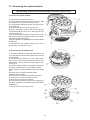
11.1 Removing the optical module ................................................................................. 33
11.2 Disposing of the product ......................................................................................... 34
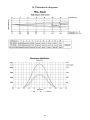
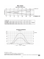
12. Photometric diagrams................................................................................................ 35
Robin Spiider TW

3
CAUTION!
Keep this device away from rain and moisture!
Unplug mains lead before opening the housing!
FOR YOUR OWN SAFETY, PLEASE READ THIS USER MANUAL CAREFULLY
BEFORE YOU INITIAL START - UP!
1. Safety instructions
Every person involved with installation and maintenance of this device have to:
- be qualied
- follow the instructions of this manual
CAUTION!
Be careful with your operations.
With a high voltage you can suer
a dangerous electric shock when touching the wires!
This device has left our premises in absolutely perfect condition. In order to maintain this condition and to en-
sure a safe operation, it is absolutely necessary for the user to follow the safety instructions and warning notes
written in this manual.
Important
The manufacturer will not accept liability for any resulting damages caused by the non-observance of this
manual or any unauthorized modication to the device.
Please consider that damages caused by manual modications to the device are not subject to warranty.
Handle the power cord and all connections with the mains with particular caution!
Make sure that the available voltage is not higher than stated on the rear panel.
WARNING! This unit does not contain an ON/OFF switch. Always disconnect power input cable
to completely remove power from unit when not in use or before cleaning or servicing the unit.
Make sure that the power-cord is never crimped or damaged by sharp edges. Check the device and the pow-
er-cord from time to time.
Always disconnect from the mains, when the device is not in use or before cleaning it. Only handle the pow-
er-cord by the plug. Never pull out the plug by tugging the power cord.
This device falls under protection class I. Therefore it is essential to connect the yellow/green conductor to earth.
The electric connection, repairs and servicing must be carried out by a qualied employee.
Do not connect this device to a dimmer pack.
During the initial start-up some smoke or smell may arise. This is a normal process and does not necessarily
mean that the device is defective.
Do not touch the device’s housing bare hands during its operation (housing becomes hot)!
For replacement use fuses of same type and rating only.
LED light emission. Risk of eye injury. Do not look into the beam at short distance of
the of the product. Do not view the light output with optical instruments or any device
that may conncentrate the beam.

4
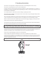
2. Operating determination
This device is a moving head for creating decorative eects and was designed for indoor use only.
This device is for professional use only. It is not for household use.
If the device has been exposed to drastic temperature uctuation (e.g. after transportation), do not switch it on
immediately. The arising condensation water might damage your device. Leave the device switched o until
it has reached room temperature.
Do not shake the device. Avoid brute force when installing or operating the device.
Never lift the xture by holding it at the projector head, as the mechanics may be damaged. Always hold the
xture at the transport handles.
When choosing the installation spot, please make sure that the device is not exposed to extreme heat, moisture
or dust. There should not be any cables lying around. You endanger your own and the safety of others!
Make sure that the area below the installation place is blocked when rigging, derigging or servicing the xture.
Always secure the xture with an appropriate safety wire.
Only operate the xture after having checked that the housing is rmly closed and all screws are tightly fastened.
The maximum ambient temperature 45°C must never be exceeded.
To avoid damage of an internal optical system of the xture, never let the sunlight (or
other light source) lights directly to the lens array, even when the xture is not working
!
Operate the device only after having familiarized with its functions. Do not permit operation by persons not
qualied for operating the device. Most damages are the result of unprofessional operation!
Please use the original packaging if the device is to be transported.
Please consider that unauthorized modications on the device are forbidden due to safety reasons!
If this device will be operated in any way dierent to the one described in this manual, the product may suer
damages and the guarantee becomes void. Furthermore, any other operation may lead to dangers like short-cir-
cuit, burns, electric shock, burns etc.
Always push the zoom module into the head before inserting the xture into the ight
case.

5
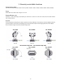
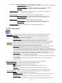
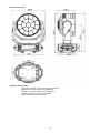
3. Fixture exterior view
The head should be locked for transportation - the tilt lock latch (7) has to be in the locked position. To unlock
the head, move this latch to unlock position before operating the xture.
The ENTER/DISPLAY ON button also serves for switching the display on when the xture is disconnected
from the mains.
1 - Lens array
2 - Yoke
3 - Handle
4 - QVGA touch screen
5 - Control buttons
6 - USB port
7 - Tilt lock
8 - 3-pin DMX OUT
9 - Ethernet IN
10 - Base
11 - Ethernet OUT
12- 3-pin DMX IN
13- 5-pin DMX IN
14- Mains IN
15- Fuse holder
16- 5-pin DMX OUT
17- Moving head

6
4. Installation
Fixtures must be installed by a qualied electrician in accordance with all
national and local electrical and construction codes and regulations.
4.1 Connection to the mains
For protection from electric shock, the xture must be earthed!
The Robin Spiider TW is equipped with auto-switching power supply that automatically adjusts to any 50-60Hz
AC power source from 100-240 Volts.
If you install a cord cap on the power cable to allow connection to power outlets, install a grounding-type (earthed)
plug, following the plug manufacturer’s instructions.
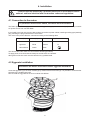
The cores in the power cable are coloured according to the following table.
Core (EU) Core (US) Connection Plug Terminal Marking
Brown Black Live L
Light blue White Neutral N
Yellow/Green Green Earth
This device falls under class one and must be earthed (grounded)!
To apply power, rst check that the head pan and tilt locks are released.
Wiring and connection work must be carried out by qualied sta!
4.2 Eggcrate installation
Disconnect the xture from mains before eggcrate installation
Screw the eggcrate (1) to the zoom module (3) by means of the three screws (2). It is possible to screw another
eggcrate to the installed eggcrate.
Do not install the eggcrate on the zoom module with diuser.

7
4.3 Diuser installation
Disconnect the xture from mains before diuser installation
Screw the diuser (1) to the zoom module (2) by means of the six screws M3x8 with washers (3).
There is a marked shape (4) of the middle pixel on the plastic lm. If you wish to use a pure ower eect (create
by means of the middle pixel), remove the marked lm from diuser before its installation. Put the diuser on
the at surface (be careful not to scratch it) and use a sharp knife to remove the marked plastic lm (4).
Note: the diuser can be installed on the eggcrate, in this case use only three screws M3x8 with washers.

8
4.4 Rigging the xture
A structure intended for installation of the xture (s) must safely hold weight of the xture(s) placed on it. The
structure has to be certicated to the purpose.
The xture (xtures) must be installed in accordance with national and local electrical and construction codes
and regulations.
For overhead installation, the xture must be always secured with a safety wire that
can bear at least 10 times the weight of the xture.
When rigging, derigging or servicing the xture staying in the area below the installation place, on bridges,
under high working places and other endangered areas is forbidden.
The operator has to make sure that safety-relating and machine-technical installations are approved by an
expert before taking into operation for the rst time and after changes before taking into operation another time.
The operator has to make sure that safety-relating and machine-technical installations are approved by a skilled
person once a year.
Allow the xture to cool for ten minutes before handling.
The xture should be installed outside areas where persons may walk by or be seated.
IMPORTANT! OVERHEAD RIGGING REQUIRES EXTENSIVE EXPERIENCE, including calculating working
load limits, installation material being used, and periodic safety inspection of all installation material and the
projector. If you lack these qualications, do not attempt the installation yourself, but use a help of professional
companies.
CAUTION: Fixtures may cause severe injuries when crashing down! If you have doubts concerning the safety
of a possible installation, do not install the xture!
The xture has to be installed out of the reach of public.
The xture must never be xed swinging freely in the room.
Danger of re !
When installing the device, make sure there is no highly inammable
material (decoration articles, etc.) in a distance of min. 0.5 m.
CAUTION!
Use 2 appropriate clamps to rig the xture on the truss.
Follow the instructions mentioned at the bottom of the base.
Make sure that the device is xed properly! Ensure that the
structure (truss) to which you are attaching the xtures is secure.
The xture can be placed directly on the stage oor or rigged in any orientation on a truss without altering its
operation characte ristics .
For securing the xture to the truss, install a safety wire which can hold at least 10 times the weight of the xture.
Use only the safety wire with a snap hook with screw lock gate.
.
.

9
Truss installation
1. Bolt the clamp (3) to the omega holder (5) with M12 bolt and lock nut through the hole in the holder.
2. Fasten the omega holders to the bottom of the base by inserting both quick-lock fasteners (2) into
the holes of the base and tighten fully clockwise.
3. Clamp the xture on a truss (6) and tighten the rigging clamps.
4. Pull the safety wire (4) through the attachment point (1) and through the handle (7) and around the truss (6)
and lock the snap hook with screw lock gate.
Use only a safety wire with a snap hook with screw lock gate.
When installing xtures side-by-side,
avoid illuminating one xture with another!
DANGER TO LIFE!
Before taking into operation for the rst time,the installation has to be approved by
an expert!

10
In order to protect the internal parts of the head from the sun, the function
PARKING POSITION must be switched ON before switching the xture o.
The PARKING POSITION function is located on the Power/Special functions channel (120-129 DMX). If the
function is on, the xture will automatically detect via G-sensor whether the xture is on the oor or hangs on
the truss or is mounted sideways on the truss and moves the pan and tilt to the position (including movement
of zoom to the front part of the head) in which the head will always face down. Owing this position of the xture
head, there is not chance to burn internal parts of the head by the sun light.
4.5 DMX-512 connection
The xture is equipped with both 3-pin and 5-pin XLR sockets for DMX input and output.The sockets are wired
in parallel.
Only use a shielded twisted-pair cable designed for RS-485 and 3-pin or 5-pin XLR-plugs and connectors in
order to connect the controller with the xture or one xture with another.
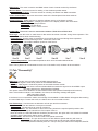
DMX - output DMX-input
XLR mounting-sockets (rear view): XLR mounting-plugs (rear view):
Building a serial DMX-chain:
Connect the DMX-output of the rst xture in the DMX-chain with the DMX-input of the next xture. Always connect
one output with the input of the next xture until all xtures are connected. Up to 32 xtures can be connected.
Caution: At the last xture, the DMX-cable has to be terminated with a terminator. Solder a 120 Ω resistor
between Signal (–) and Signal (+) into a 3-pin (5-pin) XLR-plug and plug it in the DMX output of the last xture.
1 - Shield
2 - Signal (-)
3 - Signal (+)
4 - Not connected
5 - Not connected
1 - Shield
2 - Signal (-)
3 - Signal (+)
4 - Not connected
5 - Not connected

11
4.6 Ethernet connection
The xtures on a data link are connected to the Ethernet with ArtNet communication protocol.The control soft-
ware running on your PC (or light console) has to support Art-Net protocol.
Art-Net communication protocol is a 10 Base T Ethernet protocol based on the TCP/IP.Its purpose is to allow
transfer of large amounts of DMX 512 data over a wide area using standard network technology.
IP address is the Internet protocol address.The IP uniquely identies any node (xture) on a network.
The Universe is a single DMX 512 frame of 512 channels.
The Robin Spiider is equipped with 8-pin RJ- 45 socket for Ethernet input.Use a network cable category 5 (with
four “twisted” wire pairs) and standard RJ-45 plugs in order to connect the xture to the network.
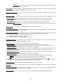
RJ-45 socket (front view): RJ-45 plug (front view):
1- TD+ 5- Not connected
2- TD- 6- RX-
3- RX+ 7- Not connected
4- Not connected 8- Not connected
Patch cables that connect xtures to the hubs or LAN sockets are wired 1:1,that is,pins with the same numbers
are connected together:
1-1 2-2 3-3 4-4 5-5 6-6 7-7 8-8
If only the xture and the computer are to be interconnected,no hubs or other active components are needed.A
cross-cable has to be used:
1-3 2-6 3-1 4-8 5-7 6-2 7-5 8-4
If the xture is connected with active Ethernet socket (e.g. switch) the network icon will appear at the
bottom right corner of the screen:
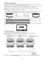
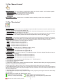
Direct Ethernet operation
Connect the Ethernet inputs of all xtures with the Ethernet network.
Option “Artnet (gMaI or gMA2)" has to be selected from “Ethernet Mode” menu on the xture.
Set IP address (002.xxx.xxx.xxx / 010.xxx.xxx.xxx) and the Universe.
(DMX address=131) (DMX address=30) (DMX address=1)
IP addres=002.168.002.004 IP addres=002.168.002.003 IP addres=002.168.002.002
Universe=1 Universe=1 Universe=1
An advised PC setting: IP address: 002.xxx.xxx.xxx / 010.xxx.xxx.xxx (Dierent from xture IP addresses)
NET mask: 255.0.0.0

12
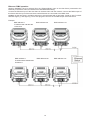
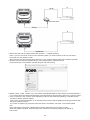
Ethernet / DMX operation
Options “Art2DMX” has to be selected from the “Ethernet Mode” menu on the rst xture (connected to the
Ethernet) in the xture chain,next xtures have standard DMX setting.
Connect the Ethernet-input of the rst xture in the data chain with the network. Connect the DMX output of
this xture with the input of the next xture until all xtures are connected to the DMX chain.
Caution: At the last xture, the DMX chain has to be terminated with a terminator. Solder a 120 Ω resistor
between Signal (–) and Signal (+) into a XLR-plug and connect it in the DMX-output of the last xture.
Example:
DMX address=1 DMX address=49 DMX address=131
IP addres=002.168.002.002
Universe=0
DMX address=1 DMX address=49 DMX address=131
IP addres=002.168.002.003
Universe=1

13
4.7 Wireless DMX operation
The wireless version of the Robin Spiider is equipped with the Lumen Radio CRMX module and antenna for
receiving DMX signal. CRMX module operates on the 2.4 GHz band.
The item " Wireless " from the menu "DMX Input" allows you to activate receiving of wireless DMX (Person-
ality--> DMX Input -->Wireless.). First two options from the "DMX Input" menu are stated in DMX chart as well
(channel Power/Special functions , range of 10-19 DMX). If DMX input option is changed by DMX command,
the change is permanently written into xture´s memory.
DMX range of 10-19 switching xture to the wired/wireless operation is active only during rst 10 sec-
onds after switching the xture on.
After switching the xture on, the xture checks both modes of receiving DMX in the following order:
1. For the rst ve seconds, the xture receives DMX signal from the wired input. If the Power/Special functions
channel is set at some DMX input option, the xture will receive DMX value according to this option. If DMX input
option is set to the wired input , this option is saved and checking procedure is nished. If DMX input option is
not set, the xture continues next 5 seconds in scanning wireless DMX signal-see point 2.
2. For the next 5 seconds the xture receives wireless DMX signal and again detects if the Power/Special
functions channel is set at some DMX input option, if not, the xture will take option which is set in the xture
menu "DMX Input".
To link the xture with DMX transmitter.
The xture can be only linked with the transmitter by running the link procedure at DMX transmitter .
After linking , the level of DMX signal ( 0-100 %) is displayed in the menu item “Wireless State“ (Information
-->Wireless State).
To unlink the xture from DMX transmitter.
The xture can be unlinked from receiver via the menu item “ Unlink Wireless Adapter“ (Information--> Wireless
State --> Unlink Wireless Adapter).
Note: If the option "Wireless In/XLR Out" is selected (Personality--> DMX Input -->Wireless In/XLR Out), the
xture receives wireless DMX and sends the signal to its wired DMX output. The xture behaves as " Wireless/
Wired" adapter.
Example:

14
5. Remotely controllable functions
Virtual colour wheel
This wheel contains 8 preset white colours (3200K, 3800K, 4200K, 4600K, 5000K, 5600K, 6300K, 6500K).
Zoom
Motorized zoom oers beam range of 4° to 50°.
Dimmer/Shutter unit
Smooth 0 - 100 % dimming is provided by the electronic control unit. This unit is also used for strobe eects
with variable speed.
Pan/Tilt
Precise pan/tilt movement due to built-in electronic motion stabilizer. The electronic motion stabilizer ensures
precise position of the xture´s head during its movement and reduces its swinging when the truss shakes.
Pan movement range: 540°,tilt movement range: 220°.

15
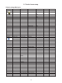
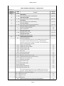
6. Control menu map
Default settings=Bold print
Tab Level 1 Level 2 Level 3 Level 4 Level 5 Level 6
Addressing Settings DMX Address 001-512
Ethernet Settings Ethernet Mode Disable
ArtNet
gMAI
gMA2
sACN
Ethernet To DMX O, On
IP Address/Net Mask Default IP Address
Custom IP Address
Net Mask
ArtNet Universe 0-255
MANet settings MANetI/II Universe 01-256
MANet Session ID 01-32
sACN Settings sACN Universe 00001-32000
sACN Priority 0-255
Klingnet Settings Disable
Enable
Information Fixture Times Power On Time Total Hours
Resetable Hours
Air Filters Elapsed Time
Alert Period 10-300
Fixture Temperatures
LEDs Temperature Current
Maximum NonRes.
Maximum Res.
Base Temperature Current
Maximum NonRes.
Maximum Res.
DMX Values Pan
:
Dimmer Fine
Wireless State Signal Quality
Unlink Wireless
Adapter
Power Channel State
Software Versions Display System
Module M
Module DR
Module PX
Product IDs Mac Address
RDM UID
RDM Label
View Logs Fixture Errors
Fixture States Power On
Power O
Fixture Position
Fixture Temperatures LEDs Temperatures
Base Temperatures

16
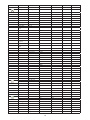
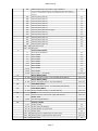
Tab Level 1 Level 2 Level 3 Level 4 Level 5 Level 6
Personality
DMX Input Wired Input
Wireless Input
Wireless In/XLR Out
Pan/Tilt Settings Pan Reverse O, On
Tilt Reverse O, On
Pan/Tilt Feedback O, On
Pan/Tilt mode Time
Speed
Pan/Tilt EMS On, O
Microphone Sen-
sitivity
1-10-20
Blackout Settings Blackout During M.C. O, On
Blackout while: Pan/Tilt moving O, On
2500W
Dimmer Curve Linear
Square Law
LEDS Output
Frequency
Standard
High
LEDs Frequency
Adjust
-6....0....+6
Init Eect Positions Pan 0-255
:
Dimmer Fine 0-255
Screen Settings Display Intensity 1-10
Screen Saver Delay O-10min.
Touchscreen Lock O-10min.
Recalibrate Touchscreen
Display Orientation Normal
Inverted
Auto
Temperature Unit °C,°F
Fan Mode Auto
High
Date & Time Settings
Default Settings
Manual Control Reset Functions Total System reset
Pan/Tilt reset
Zoom Reset
t
Manual Eect Con-
trol
Pan 0-255
:
Dimmer Fine 0-255
Stand -Alone Test Sequences Dynamic Mode
Static Mode Pan 0-255
Tilt 0-255
Zoom 0-255
MusicTrigger O, On
Preset Playback None
Test
Prog. 1
Prog. 2
Prog. 3

17
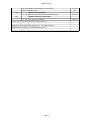
Tab Level 1 Level 2 Level 3 Level 4 Level 5 Level 6
Play Program Play Program 1
Play Program 2
Play Program 3
Edit Program Edit Program 1 Start Step 1-100
End Step 1-100
Edit Program Steps Step 1 Pan 0-255
: :
: Dimmer Fine 0-255
: Step Time 0-25,5 sec.
Step 100 Pan 0-255
:
Dimmer Fine 0-255
Step Time 0-25,5 sec.
Service Adjust DMX Values Pan 0-255
:
Dimmer Fine 0-255
Calibrations Calibrate Eects Pan 0-255
Tilt: 0-255
Calibrate Pan/Tilt EMS
Load Default Calib-
rations
Update Software

18
7. Control menu
The Robin Spiider TW is equipped with the QVGA Robe touch screen with battery backup which
allows to set the xture´s behaviour according to your needs, obtain information on its operation, test its
various parts and lastly program it, if it has to be used in a stand-alone mode.
The xture´s menu can be controlled either by the control buttons or directly by touching the icon.
Control buttons on the front panel:
[ESCAPE] button used to leave the menu without saving changes.
[NEXT] , [PREV] buttons for moving between menu items and symbols, adjusting values.
[ENTER/Display On] button used to enter the selected menu (menu item) and to conrm adjusted value.
If the xture is disconnected from mains, the button switches the touch screen on.
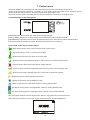
Icons used in the touch screen menu:
- [back arrow] used to move back to the previous screen (menu).
- [up arrow] used to move up on the previous page.
- [down arrow] used to move down on the next page.
- [conrm] used to save adjusted values, to leave menu or to perform desired action.
- [cancel] used to leave menu item without saving changes.
- [conrm+copy] used to save adjusted values and copy them to the next prog. step.
- [warning icon] used to indicate some error which has occurred in the xture.
- [Ethernet] used to indicate Ethernet connected.
- [display turn] used to turn the display by 180°.
- [slider control] used to recall slider system for setting desired value.
- [keyboard control] used to recall keyboard system for setting desired value.
- [air lters cleaning] used to signal that cleaning period of the air lters elapsed.
The menu page displays icons for each function that you can perform from the touch screen.
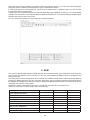
After switching the xture on, the touch screen shows the screen with the ROBE logo:

19
Note: The green icon at the top right corner of the screen indicates the level of the display battery charging. If
the whole icon is green, the battery is fully charged while the red icon indicates exhausted battery. The battery
charges during xture operation, its charging lasts cca 6 hours.
We recommend that the xture should be in operation at least 7 hours per week to keep the battery fully charged.
If you switch the xture on and this screen will not appear till 1 minute, switch the xture o and on again. If the
screen lights, the battery is exhausted. In case the screen still does not light, the battery is faulty.
This is also indicated by an error message "Faulty battery" and if such an error message appears the battery
should be replaced immediately. The lifetime of the battery is highly dependent on ambient temperature (and
consequently on base temperature). If the maximum ambient temperatures (as recorded and displayed in menu:
Information -> Fixture Temperatures -> Ambient Temperature -> Maximum NonRes.) are kept within the spec-
ied limits, the battery should last for at least two years. Shell the ambient temperatures exceed the specied
maximum temperature, the lifetime of the batteries could be considerably shortened even up to just one year
or less and also result in physical damage (battery leakage) or unreliable xture functions.
Damage caused by batteries failed due to exceeded maximum ambient temperature cannot be claimed under
warranty terms.
Touch any part of the screen or press the [ENTER/Display On] button to display the initial screen with the cur-
rent stored DMX address:
Touch the green arrow at the bottom right corner of the screen or press the [ENTER/Display On] button to enter
the " Address" menu.
Each item (such as a Tab, menu item, text box, icon) may be selected from a screen by simply touching the
item in the list or by pressing the [NEXT] or [PREV] buttons to scroll through items. With each press, the next
item is highlighted. Press [ENTER/Display On] to select the highlighted item.
Before rst xture operation, set current date and time in the menu "Date &Time
Setings" (menu path: Personality--> Date &Time Setings).
7.1 Tab " Address"
DMX Address - Select the menu to set the DMX start address.
Ethernet Settings - The menu allows all needed settings for the Ethernet operation
Ethernet Mode
Disable - The option disables Ethernet operation.
Artnet - Fixture
receives Artnet protocol
gMAI
- Fixture
receives MANet I protocol
gMA2
- Fixture
receives MANet 2 protocol
sACN
- Fixture
receives sACN protocol
Ethernet To DMX - Fixture receives
protocol
from the Ethernet input and sends DMX
data to its DMX output (xture works as an "Ethernet/DMX converter",
next xture can be connected
to its DMX output and you can build a standard DMX chain by connecting another xtures.
Only one xture has to be connected to the Ethernet.
IP Address/Net Mask - Select this menu to set IP address. IP address is the Internet protocol
address.The IP uniquely identies any node (xture) on a network.

20
There cannot be 2 xtures with the same IP address on the network!
Default IP Address -Preset IP address, you can set up only rst byte of IP address
(2 or 10) e.g. 002.019.052.086.
Custom IP Address - The option enables to set up all bytes of IP address.
Net Mask - The option enables to set up all bytes of Net Mask.
ArtNet Universe - Use
this item to set a Universe (0-255). The Universe is a single DMX
512 frame
of 512 channels.
MANet Settings - Use this menu to set parameters for MANet operation.
MANet Universe I/II - The value of this item can be set in range 1-256.
MANet Session ID - The value of this item can be set in range 1-32.
sACN Settings - Use this menu to set parameters for sACN operation.
sACN Universe - The value of this item can be set in range 1-32000.
sACN Priority - The value of this item can be set in range 0-255.
Klingnet Settings - Use this menu to enable or disable Klingnet protocol.
7.2 Tab "Information"
Fixture Times - The menu provides readouts of xture operation hours and air lters using hours.
Power On Time Hours - Select this menu to read the number of xture operation hours.
Total Hours -
The item shows the total number of the operation hours since the
Robin Spiider TW
has been fabricated.
Resetable Hours -
The item shows the number of the operation hours that the
Robin Spiider TW
has been powered on since the counter was last reset.
In order to reset this counter to 0, touch the text box next to the item "Resetable Hours:"
Air Filters - Regular cleaning of the air lters is very important for the xture´s life and performance.
Bild-up of dust, dirt and fog uid residues reduces the xture´s light output and cooling ability.
The two items of this menu help you to keep cleaning period of the air lters.
Alert period - Cleaning schedule for the xture depends on the operating environment.
It is therefore impossible to specify accurate cleaning interval. This item allows
you to change the cleaning interval of the air lters. This "alert" value is 300 hours and it
is set as default. Inspect the xture within its 300 hours of operation to see whether cleaning
is necessary. If cleaning is required, clean all air lters and change the value in this menu
on acceptable level. Min. level of alert period is 10 hours, max. is 300 hours.
Elapsed Time - The item allows you to read the time which remains to cleaning air lters.
The time period is set in the menu mentioned above.
Expired time period is signalled by a negative mark (-) at the time value and a warning icon
on the display.
Clean the lters and reset this menu item (by touching the text box next to the item
"Elapsed Time").
Fixture Temperatures - The menu is used to view temperatures of the xture´s inside.
LEDs temperatures - The menu shows temperature on the LEDs PCB .
Cur. - A current temperature of the LEDs PCB.
Max. - A maximum temperature of the LEDs PCB since the xture has
been fabricated.
Max. Res. - A maximum temperature of the LEDs PCB since the counter
was last reset.
In order to reset some counter to 0, touch desired text box under item "Max.Res."
Base Temperature - The menu shows temperature in the xture base (on the display PCB).
Current - A current temperature in the xture base.
Maximum NonRes. - A maximum temperature in the xture base since the xture has
been fabricated.
Maximum Res. - A maximum temperature in the xture base since the counter
was last reset.
In order to reset this counter to 0, touch the text box next to the item "Maximum Res."
Page is loading ...
Page is loading ...
Page is loading ...
Page is loading ...
Page is loading ...
Page is loading ...
Page is loading ...
Page is loading ...
Page is loading ...
Page is loading ...
Page is loading ...
Page is loading ...
Page is loading ...
Page is loading ...
Page is loading ...
Page is loading ...
Page is loading ...
Page is loading ...
Page is loading ...
-
 1
1
-
 2
2
-
 3
3
-
 4
4
-
 5
5
-
 6
6
-
 7
7
-
 8
8
-
 9
9
-
 10
10
-
 11
11
-
 12
12
-
 13
13
-
 14
14
-
 15
15
-
 16
16
-
 17
17
-
 18
18
-
 19
19
-
 20
20
-
 21
21
-
 22
22
-
 23
23
-
 24
24
-
 25
25
-
 26
26
-
 27
27
-
 28
28
-
 29
29
-
 30
30
-
 31
31
-
 32
32
-
 33
33
-
 34
34
-
 35
35
-
 36
36
-
 37
37
-
 38
38
-
 39
39


Robe Robin Spiider TW User manual
- Category
- Stroboscopes & disco lights
- Type
- User manual
Ask a question and I''ll find the answer in the document
Finding information in a document is now easier with AI
Related papers
-
Robe Robin Spiider User manual
-
-
-
Robe Robin Tetra 1 User manual
-
-
-
-
-
-
Other documents
-
Robin SPIIDER User manual
-
-
-
-
-
Elation DMX-512 User manual
-
-
 Cyclops Lighting FR-300W User manual
-
PXM PX163+ User manual
-
 Artistic License nanoScope Quick start guide

