Page is loading ...

2
Specifi cations / Specifi caties
Technische Daten / Spécifi cations
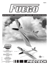
1. Wing
2. Horizontal stabilizer
3. Vertical fi n
4. Fuselage
5. Cockpit screens
6. Rudder
7. Landing gear
8. Spinner
9. Fueltank
10. Accessories
11. Accessories
12. Control rods
1. Vleugel
2. Hoogteroer
3. Richtingsroer
4. Romp
5. Cockpitvensters
6. Richtingsroer
7. Landingsgestel
8. Spinner
9. Brandstoftank
10. Toebehoren
11. Toebehoren
12. Stuurstangen
1. Flügel
2. Höhenruder
3. Seitenruder
4. Rumpf
5. Kabinenfenster
6. Seitenruder
7. Fahrgestell
8. Spinner
9. Kraftstofftank
10. Zubehör
11. Zubehör
12. Getänges
1. Aile
2. Stabilisateur
3. Dérive
4. Fuselage
5. Verrière de cabine
6. Gouverne de direction
7. Train d'atterrissage
8. Cône d'hélice
9. Réservoir
10. Accessoires
11. Accessoires
12. Tringles de commande
3
Kit contents / Inhoud van de bouwdoos
Bausatzinhalt / Contenu de la boîte
Length: 1200 mm
Wing span: 1700 mm
Wing area: 45,9 dm
2
Wing loading: 44,66 g/dm
2
Flying weight: 2050 g
Radio required: 4 ch radio with
4 std servos
Lengte: 1200 mm
Spanwijdte: 1700 mm
Vleugelopp.: 45,9 dm
2
Vleugelbel.: 44,66 g/dm
2
Vlieggewicht: 2050 g
Radiobesturing: 4 kanaals radio
4 std servos
Länge: 1200 mm
Spannweite: 1700 mm
Tragfl ügelinhalt: 45,9 dm
2
Gesamtfl achen-
belastung: 44,66 g/dm
2
Fluggewicht: 2050 g
Funkfernsteuerung:
4 Kanal
Steuerung mit
4x std servos
Longueur: 1200 mm
Envergure: 1700 mm
Surface alaire: 45,9 dm
2
Charge alaire
: 44,66 g/dm
2
Poids en vol: 2050 g
Radio requise: 4 voies avec
4 servos std
1
2
4
5
8
7
6
9
10
11
12

3
Sharp hobby knife / Scherp hobbymes /
Couteau de modéliste / scharfes Hobbymesser
Needle nose pliers / Bektang /
Pince à becs / Beißzange
Philips screw driver / Kruisschroevendraaier /
Tournevis Philips / Schraubendreher
Triangle / Driehoeksmeetlat /
Equerre à dessin / Winkel Scissors / Schaar / Ciseaux / Schere
Wire cutter / Draadstripper /
Pince coupante / Kneifzange
Drill / Boor / Perceuse / Handbohrer
Tape / Plakband / Bande adhésive / Klebeband
To assemble this model some tools are needed.
Voor het samenstellen van het model zijn er enkele gereedschappen nodig.
Zum bauen dieses Modell brauchen Sie einige Werkzeuge.
Certains outils sont requis pour assembler ce modèle.
Tools & items / Gereedschap & benodigdheden
Werkzeuge und alle Notwendigkeiten / Outils et équipements
#A120-25
Cyanoacrylate
MICRO RECEIVER 7-CH FM
PRO7.35 7-CH micro receiver
35 MHz FM
PRO7.40 7-CH micro receiver
40 MHz FM
PROTECH std servo #B305
Weight: 16g
Torque: 24Ncm
Speed: 0,14s / 60°
Dimensions: 29x25x13mm
4X STANDARD SERVO
#A500-28
5 min. Epoxy glue
WOOD
GLUE
WOOD
GLUE
Wood glue
14gr
PROTECH #M1046
SX-46 ABC BB ENGINE
2 ball bearings
1,62 HP
2000-17000 rpm
.46 SIZE ENGINE

4
Important Safety Notes.
Be sure to read right through the instructions covering assembly and operation of your model before you at tempt to operate it for the fi rst time. You are the only
person who is responsible for the safe operation of your radio-con trol led model. Young people should only be permitted to build and fl y these mod els under the
instruction and su per vi sion of an adult who is aware of the hazards involved in this activity.
Use only matching polarised connectors. All cables, connectors and the battery if home-as sem bled must be insulated to prevent short circuits. Never attempt to
combine different types of plug and socket - e.g. tin-plated and gold-plated types - as such combinations are bound to be un re li a ble.
NC batteries are capable of holding and releasing enormous amounts of energy, and as such represent a constant hazard of explosion and fi re.
We have no control over the way you build and operate your RC model aircraft, and for this rea son we are obliged to deny all liability for accidents. All we can do is
point out the hazards and make sure you are aware of them.
If you need help, please enlist the aid of an experienced modeller, a model club or enrol at a model fl ying training school. Model shops and the specialized model
press are also good sources of information. The best course is always to join a club and fl y at the approved model fl ying site.
Rubber bands deteriorate with age and become brittle. Replace them from time to time to maintain the safety and reliability of your model. Stretch all rubber bands
before use to check whether they are still strong enough for their purpose.
Motors should only be run in the open air! The powerful suction of the propeller and the volume of air which it accelerates can easily lead to accidents in enclosed
spaces (e.g. pictures falling down, curtains sucked into the propeller). The model must be held securely by an assistant at all times.
Keep well clear of the rotation fi eld of propellers - don't stand in line with it nor in front of it. You never know when some part may come loose and fl y off at high
speed, hitting you or anybody else in the vicinity. Never touch the revolving propeller with any object.
There must be no chance of any object getting in the way of the propeller and preventing it from ro tat ing.
Take care with loose clothing such as scarves, loose shirts etc. Flapping cloth can easily be sucked into the area of the propeller and then get tangled in it.
If you start your motor when the model is standing on loose or sandy ground, the propeller will suck up sand and dust and hurl it around and it could easily get in
your eyes. Wear protective goggles at such times.
Every time you intend to operate your model check carefully that the model itself and everything attached to it (e.g. pro pel ler, gearbox, RC components etc.) is in
good condition and undamaged. If you fi nd a fault do not fl y the model until you have corrected it.
Check whether your frequency is vacant before you switch on. Radio interference caused by unknown sources can occur at any time without warning. If this should
happen, your model will be uncontrollable and completely unpredictable. Never leave your radio control system unguarded, as other people might pick it up and try
to use it.
Check that nothing is in the way of the propeller before you switch on the electric motor. Never attempt to stop the spinning propeller. Electric motors connected with
a propeller should only be run when installed securely.
lf you are to fl y your model safely and avoid problems, it is essential that you are aware of its po si tion and attitude throughout each fl ight - so don't let it fl y too far
away! lf you detect a control prob lem or in ter fer ence during a fl ight, immediately land the model to prevent a potential accident. Note that the transmitter throttle
stick must be set to the OFF (motor stopped) position BEFORE you switch on the power system. To avoid the electric motor starting unexpectedly, switch on the
trans mit ter fi rst, then the receiving system. Use the reverse sequence when switching off: receiver fi rst, then the transmitter. Check that the control surfaces move in
the correct "sense" when you operate the sticks.
Please don't misunderstand the purpose of these notes. We only want to make you aware of the many dan gers and hazards which can arise if you lack knowledge
and experience, or work carelessly or irresponsibly. If you take reasonable care, model fl ying is a highly creative, instructive, enjoyable and relaxing leisure.
Belangrijke Veiligheidsinstructies
Lees de instructies betreffende montage en werking van uw model vooraleer u het de eerste maal in gebruik neemt. U alleen bent verantwoordelijk voor de veilige
werking van uw radiobestuurd model. Kinderen mogen deze modellen slechts bouwen en vliegen onder het toeziend oog van een volwassene, die zich bewust is
van de gevaren die dit met zich meebrengt.
Gebruik enkel passende gepolariseerde verbindingsstukken. Alle kabels, verbindingsstukken en de batterij, indien deze zelf samengesteld is, moeten geïsoleerd
worden om kortsluiting te voorkomen. Kombineer nooit verschillende types van pluggen en contacten (vb. tin- en goudcontacten), daar zulke combinaties onbe-
trouwbaar zijn.
NC-batterijen zijn geschikt om enorme hoeveelheden energie vast te houden en vrij te geven. Zodoende vertegenwoordigt een batterij een constant risico op explo-
sie en brandgevaar.
Wij hebben geen controle over de manier waarop u het RC-vliegtuig bouwt en gebruikt. Daarom zijn wij verplicht om alle aansprakelijkheid voor ongevallen van de
hand te wijzen. Wij kunnen u alleen maar waarschuwen voor de risico’s.
Als u hulp nodig heeft, roep dan de bijstand van een ervaren modelbouwer of een modelbouwclub in, of schrijf u in bij een modelvliegclub. Modelshops en de
gespecialiseerde pers zijn eveneens een geschikte bron van informatie. De beste les is echter zich aan te sluiten bij een club en te vliegen op de goedgekeurde
vliegplaatsen.
Rubber elastieken verslijten door het gebruik en worden broos. Vervang ze tijdig, om de veiligheid en de betrouwbaarheid van uw model te verhogen. Span alle rub-
ber elastieken op vooraleer u ze gebruikt om te controleren of ze nog sterk genoeg zijn.
Motoren mogen enkel buiten in openlucht lopen! De sterke zuigkracht van de propeller en de luchtverplaatsing die deze veroorzaakt, kan in kleine ruimten makke-
lijk een ongeval tot gevolg hebben (vb. schilderijen die naar beneden vallen, een gordijn dat in de propeller gezogen wordt). Het model moet steeds stevig worden
vastgehouden door een helper.
Houd de rotatiebaan van een propeller vrij, sta er nooit voor of in de lijn van de propeller. Er kan steeds een deel loskomen en met hoge snelheid wegvliegen, zodat
het uzelf of iemand anders in de omgeving kan verwonden. Raak de ronddraaiende propeller nooit met enig voorwerp aan. Vermijd steeds dat welk voorwerp ook
het draaien van de propeller verhindert.
Pas op met losse kleding zoals sjaals, losse shirts, … Losse kleding kan makkelijk in de propeller gezogen worden.
Als u de motor start terwijl deze op losse of zanderige grond staat, zal de propeller het zand opzuigen en rondslingeren zodat het in uw ogen kan komen. Draag dus
steeds een veiligheidsbril op zo’n momenten.
Controleer, elke keer als u een model wil gebruiken, zorgvuldig of het model en alles wat erbij hoort (vb. propeller, aandrijving, RC-onderdelen, …) in goede staat en
onbeschadigd is. Als u een fout bemerkt, vlieg dan niet met het model tot u de fout hebt opgelost.
Verzeker uzelf ervan dat de frequentie vrij is vooraleer u de zender aanzet. Radiostoringen, veroorzaakt door vreemde bronnen, kunnen op elk moment en zonder
waarschuwing voorkomen. Als dit gebeurt is uw model oncontroleerbaar en volledig onvoorspelbaar. Laat uw radiobesturing nooit onbewaakt achter, andere mensen
zouden kunnen proberen het apparaat te gebruiken.
Controleer of er niets in de baan van de propeller is vooraleer u de elektromotor aanzet. Probeer nooit de draaiende propeller te stoppen. Elektromotoren verbonden
met een propeller mogen enkel lopen als deze veilig geïnstalleerd is.
Als u uw model veilig wil vliegen en u wil problemen vermijden, dan is het essentieel dat u zich bewust bent van zijn positie en hoogte tijdens iedere vlucht. Laat het
dus niet te ver weg vliegen ! Als u een controleprobleem of storingen ontdekt gedurende een vlucht, land dan onmiddellijk om een mogelijk ongeval te voorkomen.
Zet de zenderstick voor de motorfunctie in de off-stand vooraleer u het systeem aanzet. Om te voorkomen dat de elektromotor onverwacht start, zet u eerst de zen-
der aan, later pas de ontvanger. Gebruik de omgekeerde volgorde bij het afzetten : eerst de ontvanger, dan de zender. Controleer of de roeren in de juiste richting
bewegen als u de sticks gebruikt.
Heb begrip voor het doel van deze opmerkingen. Wij willen u enkel opmerkzaam maken voor de vele gevaren en risico’s die zich kunnen voordoen als u kennis en
ervaring mist, nonchalant of onverantwoordelijk te werk gaat.
Als u redelijk zorg draagt, is modelvliegen een zeer creatieve, leerrijke, plezierige en ontspannende vrijetijdsbesteding.

6
Installing the ailerons / Montage van de rolroeren
Montierung des Querrudern / Montage des ailerons
Fig. 1
Fig. 5 Fig. 6
Fig. 2 Fig. 3
Insert the ailerons in the wing.
Put a little bit of cyanoacrylate on
one side of the hinges and check
the aileron to make sure that it
moves freely. Repeat these steps
for the other side of the hinge.
Follow the same procedure for the
right wing panel.
Fig. 1-2-3
Plaats de rolroeren in de vleugel
en doe een beetje cyano lijm op
één zijde van de scharnieren en
controleer of het roer vrij kan be-
wegen. Herhaal de stappen voor
de andere zijde.
Volg dezelfde procedure voor de
rechter vleugel.
Fig. 1-2-3
Schieben Sie der Querruder in
der Flügel.
Bringen Sie ein wenig Cyano
Klebstoff auf einer Seite des
Scharnieres und überprüfen Sie
ob das Ruder frei bewegen kann.
Wiederholen Sie die Etappen für
der andere Seite.
Wiederholen Sie die Etappen für
den Rechten Flügel.
Fig. 1-2-3
Inserez l'aileron dans le panneau
d'aile.
Appliquez sur un côté de cha-
que charnière une goutte de
colle cyanoacrylate et actionnez
l'aileron pour vérifier qu'il bouge
librement. Répétez l'opération de
l'autre côté de la charnière.
Effectuez les mêmes opérations
pour l'autre panneau d'aile.
Fig. 1-2-3

7
Assembling the wings / Samenstellen van de vleugel
Zusammenstellen des Flugelfl ächen / Assemblage des ailes
Apply wood glue into the holes of
the wing joiner and also on the
wing joiner.
Assemble the two wingparts and
keep them pressed togheter du-
ring the hardening of the glue.
Fig 4-5-6
Glue the servo tray in place.
Fig. 7
Doe een beetje houtlijm in de ga-
ten en op de vleugelbevestiger.
Duw de twee vleugelhelften sa-
men en houd ze samengedrukt
tot de lijm uitgehard is.
Fig. 4-5-6
Verlijm de servohouder in de
uitsparing.
Fig. 7
Bringen Sie ein wenig Holz-Klebe-
stoff an in die Löcher und auf den
Flächenverbinder. Drücken Sie
die zwei Flächenhälfte zusammen
und behalten Sie es so während
dem Trocknen.
Fig. 4-5-6
Kleben Sie die Servohaltering.
Fig. 7
Appliquez de la colle à bois dans
les logements de la clé d'aile des
panneaux ainsi que sur la clé
d'aile. Assemblez les 2 panneaux
et maintenez les parties ensemble
durant le séchage.
Fig. 4-5-6
Collez le support de servo en
position.
Fig. 7
Fig. 22
Fig. 6
Fig. 21
Fig. 4
TOP WING
A A
A=A
Fig. 5
Fig. 22
Fig. 21
Fig. 7
WOOD
GLUE
WOOD
GLUE
WOOD
GLUE
WOOD
GLUE

8
Placing the aileron servo / Plaatsen van de rolroerservo
Monteren des Querruderservo / Montage de servo d'ailerons
Screw the links onto the pushrod,
make sure they are of equal
length.
Fig 9-10
Place the servo in the servo tray
and fi x it using the servo screws.
Fig. 11
Attach the pushrod to the aileron
levers, make sure the servo is
centered when you attach the
pushrods.
Fig. 12
Schroef de kwiklinks op de
stuurstang, zorg dat beide stan-
gen even lang zijn.
Fig. 9-10
Plaats de servo in de servohou-
der en monteer deze met de
servoschroeven.
Fig. 11
Zorg ervoor dat de servo in de
neutraalstand staat als u de
stuurstangen aansluit.
Fig. 12
Fig. 22
Fig. 10
Fig. 21
Fig. 8
Fig. 9
Fig. 22
Fig. 21
Fig. 11 Fig. 12
Vissez les chapes sur les com-
mandes. Assurez-vous qu'elles
ont la même longueur.
Fig. 9-10
Installez et fi xez le servo sur son
support.
Fig. 11
Connectez les commandes au
guignols des ailerons et au pa-
lonnier du servo. Verifi ez que le
servo est bien en postion neutre.
Fig. 12
Konnektieren Sie den Gabelkopf
auf die Stange.
Fig 9-10
Montieren Sie den Servo im
Halter.
Fig. 11
Konnektieren Sie die Stange auf
die Ruderhörner. Uberprüfen Sie
die Neutralstellung des Servos.
Fig. 12

9
A=A
B=B
C=C
Fig. 19
Mounting the stabiliser / Monteren van het hoogteroer /
Montierung von Höhenleitwerk / Montage du stabilisateur
Fig. 26
Fig. 27
Fig. 28
Place the stabilizer on the fuse-
lage and align (Fig. 19-20). Mark
the contours of the fuselage on
both sides of the stabilizer. Re-
move the stabilizer and remove
the covering on botom en top
side of the stabilizer between
the marks.
Fig. 14-15
Glue the stabilizer in the fuse-
lage and align.
Fig. 17
Glue the elevator in the stabilizer
by applying cyano glue on both
sides of the hinges. Make sure
the elevators can move freely.
Fig. 18
Schieben Sie den Stabilisator im
Rumpf und gleichen Sie gut aus
(Fig. 19-20). Markieren Sie die
Konturen des Rumpfs auf den
Stabilisator. Entfernen Sie den
Stabilisator und entfernen Sie am
unteren und obenen Seite des
Stabilisators die Bespannfolie.
Fig. 14-15
Verkleben Sie den Stabilisator
im Rumpf und gleichen Sie gut
aus. Fig. 17
Kleben Sie die Höhenrudern
im Stabilisator, durch Cyano-
klebstoff auf beiden Seiten
der Scharniere an zu bringen.
Überprüfen Sie ob die Rudern
frei bewegen können.
Fig. 18
Placez le stabilisateur sur l'arrière
du fuselage. Alignez le stabilisa-
teur (Fig. 19-20), tracez sur les 2
faces du stabilisateur à l’aide d’un
stylo à bille le contour du fu se lage.
Retirez le stabilisateur, découpez
au cutter le fi lm de recouvrement
à l’intérieur de votre tracé.
Fig. 14-15
Appliquez de la colle époxy sur la
zone en bois du stabilisateur que
vous venez de découvrir, alignez
le stabilisateur à nouveau (Fig.
19-20) et laissez sécher.
Fig. 17
Appliquez sur les deux côtés
de la charnière une goutte de
colle cyanoacrylate et assurez-
vous que la gouverne bouge
librement.
Fig. 18
Plaats de stabilo op de romp en
lijn goed uit (Fig. 19-20). Markeer
de contouren van de romp op de
stabilo. Verwijder de stabilo uit de
romp en verwijder de bespanning
aan boven en onderzijde van de
stabilo tussen de markeringen.
Fig. 14-15
Verlijm de stabilo in de romp met
epoxy en lijn goed uit.
Fig. 17
Verlijm de hoogteroeren op de
stabilo door aan beide zijden van
de scharnieren cyano lijm aan te
brengen. Zorg ervoor dat de roe-
ren vrij kunnen bewegen.
Fig. 18
Fig. 18
Fig. 30
A=A
B=B
Fig. 41
Fig. 20
Fig. 13
Fig. 16
Fig. 17
Fig. 14 Fig. 15

10
Installing the vertical fi n / Montage van het richtingsroer
Montierung des Seitenruders / Montage de la dérive
Fig. 34 Fig. 35
Fig. 36
A=A
B=B
90°
Fig. 41
Fig. 26
Fig. 37 Fig. 38 Fig. 39
Cut away some covering (Fig.
21) Slide the vertical fi n in the
fuselage. Mark the contours of
the fuselage on both sides of the
vertical fi n. Remove the vertical fi n
and remove the covering on both
sides of the vertical fi n between
the marks.
Fig. 22
Glue the vertical fi n in the fuse-
lage and align.
Fig. 23
Glue the rudder in the vertical fi n
by applying cyano glue on both
sides of the hinges.
Fig. 24
Make sure the rudder can move
freely.
Entfernen Sie die Bespannfoli-
en (Fig. 21). Schieben Sie die
Vertikale Flache im Rumpf und
gleichen Sie gut aus. Markieren
Sie die Konturen des Rumpfs auf
beide Seiten der vertikale Flache.
Entfernen Sie die vertikale Flache
und entfernen Sie die Bespannfo-
lie am beiden Seiten der vertikale
Flache.
Fig. 22
Verkleben Sie die vertikale
Flache im Rumpf und gleichen
Sie gut aus.
Fig. 23
Kleben Sie die Seitenruder in
der vertikale Flache, indem Sie
Cyanoklebstoff auf beiden Sei-
ten der Scharniers anbringen.
Fig. 24
Überprüfen Sie ob die Rudern
frei bewegen können.
Decoupez l'entoilage (Fig. 21).
Installez la dérive sur le fuselage
et tracez le contour du fuselage
sur la dérive.
Enlevez l'entoilage en-dessous
de votre tracé.
Fig. 22
Appliquez de la colle époxy
30min. sur la partie désentoilée
de la dérive et dans le logement
du fuselage.
Contrôlez son alignement (Fig.
26) et maintenez en place durant
le séchage.
Fig. 23
Installez la gouverne de direc-
tion sur la dérive et collez les
charnières à la colle cyano.
Fig. 24
Assurez-vous que la gouverne
bouge librement.
Verwijder de bespanning (Fig. 21)
Schuif het kielvlak in de romp.
Markeer de contouren van de
romp op beide zijden van het
kielvlak. Neem het kielvlak uit de
romp en verwijder de bespanning
aan beide zijde van het kielvlak
onder de markeringen.
Fig. 22
Verlijm het kielvlak in de romp met
epoxy en lijn goed uit.
Fig. 23
Verlijm de richtingsroeren op het
kielvlak door aan beide zijden van
de scharnieren cyano lijm aan te
brengen.
Fig. 24
Zorg ervoor dat het roer vrij kan
bewegen.
Fig. 21 Fig. 22
Fig. 23
Fig. 24

11
Installing the control horns / Montage van de roerhoornen
Montierung von die Hörner / Installation des guignols
Connect the metal pushrod to the
plastic rod.
Fig. 27-28
Remove the fuselage covering
and insert the pastic push rod.
Fig. 29
Insert the pushrod in the fuselage.
Fig. 30-31
Connect the pushrod to a plastic
clevis and secure with the rubber
band.
Position the control horn (Fig. 32)
on the elevator. Align and make
sure the holes of the horn are
directly above the hinges axle.
(See Fig. 35)
Mark the fi xation holes of the horn
on the elevator and drill the holes
through the elevator.
Fig. 33
Screw the control horn in place
with the 2 delivered screws and
the nylon support.
Remove excessive screw thread.
Fig. 34
Draai de stuurstang in het plastic
stuurbuisje.
Fig. 27-28
Verwijder de bespanning ter
hoogte van het doorvoerbuisje
in de romp.
Fig. 29
Schuif de stuurstang door het
doorvoerbuisje. Fig. 30-31
Bevestig de kwiklink aan de
roerhoorn en beveilig deze met
een rubberen beveiligingsring.
Plaats de roerhoorn (Fig 32) op
het hoogteroer. Lijn de hoorn uit
met de servoarm en zorg ervoor
dat de gaatjes in de hoorn juist
boven het scharnierpunt van het
roer staan (zie Fig. 35).
Duid de gaatjes aan voor de be-
vestiging van de hoorn en boor
de gaatjes door het hoogteroer.
Fig. 33
Bevestig de hoorn met behulp
van de 2 schroefjes en de nylon
verstevigers, verwijder de overtol-
lige schroefdraad.
Fig. 34
Konnektieren Sie den Gabelkopf
auf die Stange. Fig. 27-28
Entfernen Sie die Spannfolien fur
die Stange und Schieben Sie die
Stange in den Rumpf. Fig. 29
Stellen Sie den Ruderhorn auf
den Querruder. Gleichen Sie den
Horn aus mit den Servo-Hebel
und überprüfen Sie ob die Löcher
des Horns übereinstimmen mit
den Scharnierpunkt des Ruders,
wie auf der Zeichnung Fig. 35.
Schliessen Sie den Gabelkopf am
Ruderhorn an und fi xieren Sie mit
einem Gummiband.
Markieren Sie die Löcher zum
Befestigung des Hörner (Fig 32)
und bohren Sie durch das Hohen-
ruder. Fig. 33
Schrauben Sie den Ruderhorn zu-
sammen mit der Nylon Gegenplat-
te auf dem Ruder und
schneiden
Sie das Überfl ußige ab.
Fig. 34
Assemblez la commande en
utilisant la gaine de longueur
mediane. Ne mettez pas encore
la chape.
Fig. 27-28
Decoupez l'entoilage sur l'arrière
du fuselage pour le passage de la
commande de profondeur.
Fig. 29
Glissez la commande dans la
gaine qui est déjà dans le fuse-
lage et faites sortir la commande à
l'arrière du fuselage. Fig. 30-31.
Connectez la chape sur la com-
mande et sécurisez avec le bra-
celet en caoutchouc.
Positionnez le guignol (Fig. 32)
sur la gouverne de profondeur.
Assurez-vous que l'axe des trous
de réglage du guignol est aligné
avec l'axe des charnières de
l'aileron. (Voir Fig. 33).
Pointez et percez les trous de
fi xation du guignol.
Fixez à l'aide des 2 vis et de la
plaquette de renfort en nylon.
Coupez les vis qui dépassent.
Fig. 34
Fig. 27 Fig. 28
Fig. 33
Fig. 29
Fig. 34
Fig. 30 Fig. 31
Fig. 32
Fig. 35

12
Fig. 38
Installing the servos & pushrods / Monteren van de servo's en stuurstangen
Montieren von Servos und Gestängen / Montage des servos et des tringles de commandes
Fig. 36
Install the servos with their silent
blocks. Cut off the servoarms
which you do not use. Make
sure the servos are in neutral
position.
Fig. 37
Connect the pushrods to the servo
using a clevise and rubbber band
to secure it.
Fig. 38
Installeer de servo's met hun
rubberen blokjes. Snijd de armen
die u niet gebruikt van de servo's.
Zorg ervoor dat de servo's in neu-
trale stand staan.
Fig. 37
Bevestig de stuurstangen aan
de servo's met behulp van een
kwiklink en veiligheidsring.
Fig. 38
Bringen Sie die Servos mit ihren
Kunststoff Blöcken an. Schneiden
Sie die überflüssige Servoar-
men ab, die Sie nicht benützen.
Überprüfen Sie ob die Servos in
Neutralstellung sind.
Fig. 37
Befestigen Sie die Gestänge am
Servo mit ein Gabelköpfe und
Sicherungsring.
Fig. 38
Installez les servos avec leurs
blocs en caoutchouc. Découpez
les parties superflues des pa-
lonniers. Assurez-vous que les
servos sont en position neutre.
Fig. 37
Raccordez les commandes aux
servos.
Fig. 38
Fig. 37
Fig. 42
Installing the fuel tank / Installeren van de brandstoftank
Montieren von Kraftstoftank / Assemblage et installation du réservoir
Assemble the fuel tank as shown
Fig. 39-40-41.
Install the fuel tank in the fuse-
lage.
Fig. 42
Montieren Sie den Kraftstofftank
wie gezeigt.
Fig. 39-40-41
Installieren Sie den Kraftstofftank
wie auf die Abblidungen.
Fig. 42
Assemblez le réservoir comme
illustré.
Fig. 39-40-41
Installez-le comme représenté.
Fig. 42
Stel de brandstoftank samen
zoals getoond op de foto's.
Fig. 39-40-41
Installeer de brandstoftank in de
romp.
Fig. 42
Fig. 39
Fig. 63 Fig. 64
Fig. 40 Fig. 41

13
Assembling the landing gear / Samenstellen van het landingsgestel /
Zusammenbau des Fahrgestells / Installation du train d'atterrissage
Fig. 43
Slide the support of the landing
gear in the fuselage. Adjust the
slot when necessary. Fig. 44
Secure them with the two plastic
fixation parts as shown. Fig.
45-46
Fix the wheels on the supports
and secure them with the wheel-
stoppers.
Fig. 48
Schieben Sie die Unterstützung
des Fahrgestells im Rumpf.
Fig. 44
Fixieren Sie mit den 2 kunststoff
Fixierungsteilen wie abgebildet.
Sicheren Sie die Räder auf den
Unterstützungen mit den Stell-
ringen.
Fig. 48
Insérez les 2 jambes du train dans
le fuselage. Rectifiez les trous
d'insertion dans le fuselage pour
les jambes si besoin. Fig. 44
Fixez les 2 plaques de fi xation
comme montré. Fig. 45-46
Installez les roues et arrêts de
roue. Assurez-vous que les roues
tournent librement.
Fig. 48
Schuif de steunen van het lan-
dingsgestel in de romp. Indien
nodig de gleuf een beetje aanpas-
sen. Fig. 44
Bevestig de steunen met de 2
kunststof fixatiestukjes zoals
afgebeeld. Fig. 45-46
Bevestig het wiel met de wielstop-
pers op de steunen.
Fig. 48
Fig. 44 Fig. 45
Fig. 46
Fig. 47 Fig. 48
Install the tail wheel as shown.
Fig. 49-50-51
Montieren Sie das Spornrad Fig.
49-50-51.
Montez la roulette Fig. 49-50-51Installeer het staartwiel zoals
afgebeeld. Fig. 49-50-51
Fig. 49 Fig. 50 Fig. 51

14
Installing the engine / Monteren van de motor
Montieren von Motor / Installation du moteur
Fig. 55
Fig. 54
Installing the steering rod to the carburettor / Monteren van de stuurstang op de carburator
Das Rohr zum Vergaser anbringen / Installation de la commande de carburateur
Use the holes in the fuselage to
fi x the tube. Slide the steering rod
in the tube. Fig. 52-53
Schieben Sie das Rohr durch den
Führungsrohr. Fig. 52-53
Utilisez les trous de passage pour
inserer la gaine de la commande
du carburateur.
Fig. 52-53
Gebruik de gaatjes in de romp
om de doorvoerbuis van de stuur-
stang in te steken.Fig. 52-53
Fig. 53Fig. 52
Fig. 56
Fig. 57
Mark the position of the engine,
drill ø3mm holes in the engine
mount (adjust where necessary).
Make sure you apply 2° side
thrust Fig. 54-55-56-57-58.
Markieren und bohren Sie ø3mm
Bohrungen im Motorstütze mit 2°
side thrust.
Fig. 54-55-56-57-58
Marquez la position du moteur
et percez les trous ø3mm de
fi xation.
Adaptez le bâti si nécessaire.
Respectez un angle de 2° pour
l'anticouple.
Fig. 54-55-56-57-58
Markeer de positie van de motor
en boor de ø3mm bevestigings-
gaten in de motordrager. Pas de
motorsteun aan waar nodig.
Zorg dat de gaten uitgelijnd zijn
zodat de motor 2° zijwaarts is
geplaatst. Fig. 54-55-56-57-58
2°
Fig. 58

15
Use the special nuts and screws
to fi x the engine to the engine
support. Fig 62-63-64
Benützen Sie die Spezielle Müt-
tern und Schrauben für die Be-
festigung des Motors an der
Motorstütze. Fig. 62-63-64
Utilisez les écrous et les vis pour
la fi xation du moteur sur le bâti
moteur. Fig. 62-63-64
Gebruik de speciale moeren en
bouten voor de bevestiging op de
motorsteun. Fig. 62-63-64
Push rod + tube
Fig. 60
Fig. 59
Fig. 63Fig. 62
Fig. 61
Install the throttle servo and slide
the control rod in the tube. Fix it
to the carburetor and the servo
arm. Fig. 59-60-61
Montieren Sie den Gas Servo,
schieben Sie das Rohr durch
den Führungsrohr und verbin-
den Sie es am Vergaser und am
Servohebel. Fig. 59-60-61
Installez le servo de gaz dans le
fuselage et introduisez la com-
mande de gaz dans la gaine.
Connectez la commande sur le
carburateur et au palonnier du
servo. Fig. 59-60-61
Installeer de gasservo en sluit de
stuurstang van het gaskanaal aan
op de carburator en de servo. Fig.
59-60-61
Fig. 64

16
Final assembly / Finale montage
Endmontierung / Installation fi nal
Use the supplied screws to fi x the
fuel tank cover Fig. 66-67, and
windows Fig. 68-69. Cut away
the excess pushrod support and
screw the fuel tank support in
place Fig. 71-72.
Glue the dowels in place Fig. 73
Place the wing centered and mark
the position of the wooden strip.
Fig. 74
Remove the covering on the in-
side of the markings
Fig. 75 Glue the strip in place
using epoxy.
Fig. 76
Fixez la trappe sous le fuselage.
Fig. 66-67
Fixez les vitres sur le fuselage.
Fig. 68-69
Enlevez le support de gaine
inutilisé et bloquez la position du
réservoir en fi xant la plaque dans
le fuselage. Fig. 70-71
Installez les tourillons de fi xation
d'aile. Appliquez un peu de colle
par l'intérieur pour le blocage.
Fig. 73
Positionez l'aile sur le fuselage
(bien centrée) et placez la plaque
de renfort sur l'aile et tracez le
contour. Fig. 74 Enlevez la plaque
et découpez l'entoilage à ± 2mm à
l'intérieur de votre tracé. Fig. 75.
Collez la plaque à la colle époxy.
Fig. 76
Gebruik de meegeleverde schroef-
jes om de afdekking Fig. 66-67 en
ramen Fig. 68-69 te bevestigen.
Snij het overtollige buishoudertje
weg en installeer de brandstoftank
steun. Fig. 71-72
Lijm de rondhoutjes in positie
Fig. 73
Plaats de vleugel mooi uitgelijnd
op de romp en plaats het verstevi-
gingsplankje, markeer de omtrek .
Fig. 74. Verwijder de bespanning
op de vleugel binnen de contour-
lijnen. Fig. 75
Verlijm het plaatje op de vleugel
met epoxy. Fig. 76
Fig. 65 Fig. 66 Fig. 67
Fig. 68 Fig. 69 Fig. 70
Fig. 71 Fig. 72 Fig. 73
Fig. 74 Fig. 75 Fig. 76
Montieren Sie den Deckel Fig.
66-67, Kabinenhaube Fig. 68-69
und Kraftstofftank Fig. 71-72 mit
Schrauben.
Kleben Sie die Holzdubel.
Fig. 73
Bringen Sie die Fläche ims Zen-
trum des Rumpf und Markieren
Sie die Konturen. Fig. 74
Entfernen Sie die Bespannfolie.
Fig. 75 Kleben Sie das Bret-
tchen.
Fig. 76

17
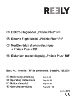
Center of gravity and rudder defl ections / Zwaartepunt en roeruitslagen
Schwerpunkt und Ruderausschlägen / Centre de gravité et débattements des gouvernes
12mm
12mm
25mm
25mm
15mm
15mm
75mm to 80mm
Installing the receiver and the battery / Installeren van de ontvanger en de batterij
Anbringen des Emfängers und des Akkus / Installation du récepteur et de l'accu
Fit the receiver in the fuselage and
protect it with some foam. Fit the
battery and secure it. Drill a little
hole in the fuselage to pass the
antenna and fi x the antenna with
tape to the back of the fuselage.
Make a little hole in the fuselage
to install the switch.
Fig. 77
Passen Sie den Empfänger im
Rumpf und Schützen Sie ihn mit
etwas Schaumstoff. Stellen Sie
der Akku im Rumpf und schützen
Sie mit Schaumstoff. Bohren Sie
ein kleines Loch im Rumpf um die
Antenne zu führenund befestigen
Sie die Antenne an der Rückseite
des rumpfs fest mit Klebeband.
Schneiden Sie ein kleines Loch
in den Rumpf um den Schälter
zu installieren.
Fig. 77
Installez et protégez le récep-
teur, installez la batterie et
veillez à ce qu'elle ne puisse pas
bouger pendant le vol.
Faîtes un petit trou pour sortir
l'antenne et faîtes-la courir le
long du fuselage, tendez-la et
collez l'extrémité avec du ruban
adhésif. Coupez un petit trou
dans le fuselage et installez
l'intérupteur.
Fig. 77
Plaats de ontvanger in de romp
en bescherm hem met een beetje
schuimrubber. Plaats de batterij
en blokkeer met schuimrubber.
Boor een gaatje in de romp om
de antenne door te voeren en
kleef deze vast aan de achterzi-
jde van de romp met een stukje
kleefband. Maak een klein gat
in de romp om de schakelaar te
installeren.
Fig. 77
Fig. 78

18
Adjustments / Afregelingen
Justage / Réglages
The correct adjustment of your
aircraft is very important. Check
carefully that all control surfaces
move in the correct direction. If
they do not move in the correct
direction, you can reverse the
servo direction on your trans-
mit ter.
It is very important that you check
the position of the CG. Put a mark
on the underside of the wing (left
and right) at 80 mm from the
leading edge (front of the wing),
and place the model on a table
nose towards you. Place one
fi nger on each mark and lift the
plane. There are special supports
available in your local modelshop
to help checking the CG. Always
check the CG with an empty
fuel tank.
Check the CG each time before
you fl y your model, a bad CG will
give serious fl ying problems.
Les réglages de votre avion sont
très importants, contrôlez que
toutes les gouvernes bougent
dans la bonne direction par
rap port aux ordres donnés. Au
besoin vous pouvez inverser le
sens de rotation des servos via
votre télécommande.
Egalement très important, le
re spect du centre de gra-
vité. Sur le dessous de l’aile (à
gauche et à droite), faites un
repère à 80 mm à partir du bord
d’attaque (bord avant) de l’aile,
mettez l’avion sur une table face
à vous. Placez un doigt (ou vous
pouvez également improviser
un autre système avec une
planche et 2 tourillons de bois)
sur chaque repère et soulevez-
le, examinez la réaction de votre
avion.
Contrôlez toujours avant chaque
vol avec le réservoir vide que le
centre de gravité est correcte,
un CG décalé et vous courez à
la ca tas tro phe!
Het afregelen van uw vliegtuig is
zeer belangrijk. Kijk goed na of
alle stuurbevelen juist zijn.
Om de te controleren of alles
juist functioneert gaat u achter
het vliegtuig staan. Mocht een
stuurcommando de foutieve
richting uitdraaien, dan kan deze
draairichting op de radiobestu-
ring aangepast worden door de
draairichting van de servo om
te keren.
Uiterst belangrijk is de juiste lig-
ging van het zwaartepunt. Plaats
aan de onderkant van de vleugel
een merkteken ( zowel op de lin-
ker- als de rechtervleugel) op 80
mm van de voorlijst, en plaats
het model op een tafel met de
neus naar u gericht.Plaats uw
wijsvingers langs beide zijden
van de romp op het voorziene
merkteken zodat het model op
de vingertoppen gaat balance-
ren. Er bestaan in de vakhandel
eveneens speciale steunen voor
het controleren van het zwaar-
tepunt. Het controleren van het
zwaartepunt dient altijd met lege
tank te gebeuren.
Controleer het zwaartepunt
voor elke vlucht, een verkeerde
ligging van het zwaartepunt
kan ernstige vliegproblemen
veroorzaken.
Die korrekte Justage Ihres
Flugzeuges ist sehr wichtig.
Überprüfen Sie sorgfältig, ob
alle Steuerflächen in die kor-
rekte Richtung bewegen. Wenn
sie nicht in die korrekte Rich-
tung umziehen, können Sie die
Servorichtung auf Ihren Sender
umkehren.
Es ist sehr wichtig, daß Sie die
Position des Schwerpunkts
überprüfen. Setzen Sie eine
Markierung auf die Unterseite
des Flügels (links und rechts)
bei 80 Millimeter vom führenden
Rand (Frontseite des Flügels),
und setzen Sie das Modell auf
eine Tisch Nase in Richtung zu
Ihnen. Setzen Sie einen Finger
auf jede Markierung und heben
Sie das Modell an. Es gibt die
speziellen Unterstützungen zum
überprüfen von das Schwerpunkt,
die in Ihrem lokalen Einzelhandel
vorhanden sind. Überprüfen Sie
immer das Schwerpunkt mit
einem leeren Kraftstofftank.
Überprüfen Sie das Schwerpunkt
immer bevor Sie Ihr Modell fl ie-
gen, ein schlechter Schwerpunkt
gibt ernste Flugprobleme.

Ask your local R/C model shop
PROTECH
®
is a registered trademark
Lammerdries Oost 23B • B-2250 Olen
Tel.: +32 (0)14 25 92 83 • Fax: +32 (0)14 25 92 89
[email protected] • http://www.protech.be
All you need is inside …
our PROTECH CATALOG (300pages FULL COLOUR)
/