Page is loading ...

Montage- und Bedienungsanleitung
Assembly and operating instructions
Notice de montage et d´utilisation
Crazy Boy
No. 3159

Crazy Boy
2
Bauanleitung, Assembly instructions, Notice de montage
3159
No.
Technische Daten
Spannweite: ca. 835 mm
Länge: ca. 805 mm
Gesamtflächeninhalt: ca. 24 dm
2
Fluggewicht: ca. 400 g
Gesamtflächenbelastung: ca. 16 g/dm
2
Nicht enthaltenes Zubehör siehe Beilageblatt
Werkzeuge und Hilfsmittel siehe robbe Hauptkatalog
Allgemeine Hinweise für den Bauablauf
Die Numerierung entspricht im wesentlichen der Reihenfolge
des Bauablaufs.
Verschaffen Sie sich in Verbindung mit den Abbildungen und
Kurztexten einen Überblick über die jeweiligen Bauschritte.
Das Auffinden der Stanzteile erleichtern die
Identifikationszeichnungen auf Seite 5.
Verklebungen von Depron®
Klebearbeiten an Depron® Teilen nur mit Foam Speed aus-
führen.
Kleber auf Nitro- und Polyesterbasis und normaler
Sekundenkleber führen zur Zerstörung des Werkstoffs.
Richtungsangaben wie z. Bsp. „rechts“ sind in
Flugrichtung zu sehen.
Hinweise zur Fernsteueranlage
Als Fernsteuerung benötigen Sie eine Anlage ab 4 Kanälen
und 4 Servos sowie einen elektronischen Flugregler.
Orientieren Sie sich vor Baubeginn über die
Einbaumöglichkeit der zu verwendenden Fernsteuerung.
Sollte eine ander
e, als die von uns vor
geschlagene
Steuerung verwendet werden, können Sie sich nach dem
Einbauschema richten.
Caractéristiques techniques
envergure : approx. 835 mm
longueur : approx. 805 mm
surface alaire totale : approx. 24 dm
2
poids en ordre de vol: approx. 400 g
charge alaire à la surface totale : approx. 16 g/dm
2
Accessoires non contenus dans la boîte de construction,
cf. feuillet joint.
Outillage et accessoires de montage, cf. catalogue général
robe.
Recommandations générales concernant les séquences
de construction.
La numérotation correspond en règle générale à l’ordre d’in-
tervention dans la construction.
A l’aide des illustrations et des textes les accompagnant per-
mettent de se familiariser avec les diverses étapes de la con-
struction.
L’identification des pièces estampées est facilitée par les
schémas d’identification de la page 5.
Collage des pièces en Depron®
N’effectuer les travaux de collage sur les pièces en Depron®
qu’avec le produit Foam Speed.
Les colles à base de nitrométhane ou de polyester et les
colles cyanoacrylates normales provoquent la destruction du
matériau.
Les indications directionnelles telles que droite ou gauche,
par exemple, sont à considérer dans le sens du vol.
Recommandations concernant l’ensemble de radiocom-
mande
L’ensemble de radiocommande approprié est un ensemble
de radiocommande à partir de quatre voies et de quatre ser-
vos accompagnés d’un variateur électr
onique pour le moteur
de l’hélice.
Specification
Wingspan: approx. 835 mm
Length: approx. 805 mm
Total surface area: approx. 24 dm
2
All-up weight: approx. 400 g
Total surface area loading: approx. 16 g / dm
2
See separate sheet for accessories not included in the kit.
See the main robbe catalogue for details of tools and aids
to building.
Sequence of assembly
In general terms the numbering of the kit components
reflects the sequence of assembly.
To gain a clear idea how the model goes together please
study the illustrations and brief instructions.
You will find identification drawings on page 5 which will
help you locate the die-cut parts.
Gluing Depron® components
Use only robbe Foam-Speed (foam-safe cyano) to glue the
Depron® components.
Using ordinary cyano-acrylate, or any adhesive based on
cellulose or polyester, will instantly ruin the material.
Directions such as “right-hand” are as seen from the tail
of the model looking forward.
The radio control system
To control the model you will need a radio control system
with at least four channels, four servos and an electronic
speed controller.
Before you start construction check that your RC system
components will fit in the suggested locations.
If you wish to use a radio control system other than the one
we r
ecommend you can still base your installation on the
arrangement shown.

Crazy Boy
3
Bauanleitung, Assembly instructions, Notice de montage
3159
No.
However, you may have to make allowance for minor differ-
ences in component sizes.
The stated control surface travels represent average values.
You may wish to reduce or increase them to suit the power
system and your personal piloting preferences.
Controlling the aileron servos
The aileron servos can be connected to a single receiver
channel using a Y-lead, or to two separate channels using
a pair of extension leads.
If you prefer the second option, and you have a computer
radio control system with suitable facilities, you can config-
ure the ailerons to work as flaps in opposition to the eleva-
tors, which further increases the model’s manoeuvrability.
The power system
The Crazy Boy can be fitted either with a direct-drive exter-
nal rotor (out-runner) brushless motor, or a geared motor,
either of the brushed or conventional brushless type.
Both versions are shown in Figs. 2 and 3, and 4 to 6. The
different motor bulkheads (2BR, 3BR for direct-drive
motors, 4B, 5B for geared motors) are included in the kit.
It is important to select the motor and matching speed con-
troller before you start building the model.
Kit contents
No. Description No. off
1 Fuselage 1
2BR Motor bulkhead 1
3BR
Doubler 1
--
M3 scr
ew 2-4
4B
Motor bulkhead
1
5B
Doubler 1
-- Self-tapping screw, 2.2 Ø x 9.5 mm 2
Avant d’entreprendre le montage vérifier les conditions
d’implantation de l’ensemble de radiocommande que vous
souhaitez installer.
Si vous utilisez un ensemble de radiocommande autre que
celui que nous recommandons, ajustez les cotes d’intégra-
tion des éléments utilisés en fonction des indications du
schéma d‚implantation
Compenser les différences de cote existantes.
Le débattement des gouvernes indiqué constitue une
valeur moyenne qu’il faut augmenter ou réduire en fonction
des habitudes de pilotage du pilote ou de l motorisation
mise en place.
Recommandations concernant les servos d’aileron
Il est possible de raccorder les servos d’aileron à l’aide d’un
cordon Y relié à une sortie u récepteur ou à l’aide de deux
cordons Y branchés sur deux sorties différentes du récep-
teur.
Avec un raccordement à l’aide de cordons rallonge sur un
ensemble de radiocommande informatique il est possible
d’utiliser les ailerons comme volets d‘atterrissage en les
mixant avec la profondeur pour augmenter la maniabilité du
modèle.
Recommandations concernant la motorisation
Dans le modèle Crazy-Boy il est possible d’installer au
choix un moteur sans balais (rotor extérieur) avec un
entraînement direct ou un moteur à balais ou un moteur
sans balais à rotor intérieur avec un engrenage.
Les deux variantes sont présentées sur les fig. 2 et 3 ou 4
à 6. Les couples moteurs différents nécessaires ((2BR, 3BR
pour l‘entraînement direct, 4B, 5B pour l‘entraînement à
engr
enage) sont joints.
Avant d‘installer le moteur, sélectionner le variateur appro-
prié.
Maßdifferenzen sind von Ihnen selbst auszugleichen.
Die angegebenen Ruderausschläge stellen einen Mittelwert
dar. Je nach Steuergewohnheiten und Motorisierung sind
diese entsprechend zu verkleinern oder zu vergrößern.
Hinweise zu den Querruderservos
Die Querruderservos können mit einem V-Kabel an einem
Empfängerkanal oder mit 2 Verlängerungskabeln an 2
getrennten Kanälen angeschlossen werden.
Bei Anschluß mit Verlängerungskabeln und einer
entsprechenden Computer-Fernsteuerung können die
Querruder als Klappen zum Höhenruder zugemischt wer-
den, was die Wendigkeit des Modells erhöht.
Hinweise zur Motorisierung
In den Crazy-Boy kann wahlweise ein Brushlessmotor
(Außenläufer) für Direktantrieb oder ein Bürstenmotor bzw.
Brushless-Innenläufer mit Getriebe eingebaut werden.
Beide Varianten sind in den Bildern 2 und 3 bzw. 4 bis 6
dargestellt. Die erforderlichen, verschiedenen Motorspanten
(2BR, 3BR für Direktantrieb, 4B, 5B für Getriebe-Antrieb)
sind beigefügt.
Vor Baubeginn den Motor mit entsprechendem Regler
auswählen.
Baukasteninhalt
Nr. Bezeichnung Stück
1 Rumpf 1
2BR Motorspant 1
3BR Aufdopplung 1
--
Gewindeschraube M3
2-4
4B
Motorspant
1
5B
Aufdopplung 1
-- Blechschraube Ø 2,2 x 9,5 mm 2

Crazy Boy
4
Bauanleitung, Assembly instructions, Notice de montage
3159
No.
6 Keil 1
7 Hauptspant vorn 1
8 Halbspant 2
9 Längsleiste, 0,5 x 10 x 150 2
10 Hauptspant hinten 1
11 RC-Platte 1
12 Höhenruder 1
13 Höhenleitwerk 1
14 Seitenruder 1
15 Seitenleitwerk 1
16 Ruderhorn 2
17 Seitenrudergestänge 1
18 Höhenrudergestänge 1
19 Kunststoffrohr 4
20 Hauptfahrwerk 1
21 Rad, zweiteilig 2
22 Sicherungsscheibe 4
23 Stützspant 1
24 Hecksporn 1
25 Querruder 2
26 Tragfläche 1
27 Servorahmen 2
28 Randverstärkung 1
29 Ruderhorn 2
30 Querrudergestänge 2
31 Kunstoffrohr 4
32 Tragflächendübel 2
33 Gummiring 2-4
34 Spinner 1
35 Spinner-Rückwand 1
36 Rückwandboden 1
37 Klötzchen 4
38 Blechschraube, Ø 2,2 x 6,5 mm 4
Contenu de la boîte de construction
n° désignation nombre de pièces
1 fuselage 1
2BR couple-moteur 1
3BR doublure 1
-- tige filetée M3 2-4
4B couple-moteur 1
5B doublure 1
-- vis autotaraudeuse Ø 2,2 x 9,5 mm 2
6 coin 1
7 demi-couple avant 1
8 demi-couple 2
9 longeron, 0,5 x 10 x 150 2
10 demi-couple arrière 1
11 platine de radiocommande 1
12 gouverne de profondeur 1
13 stabilisateur 1
14 gouverne de direction 1
15 dérive 1
16 guignol 2
17 tringle de gouverne de direction 1
18 tringle de gouverne de profondeur 1
19 tube en plastique 4
20 atterrisseur principal 1
21 roue en deux parties 2
22 circlips 4
23 couple d'étai 1
24 éperon de queue 1
25 aileron 2
26 aile 1
27 encadrement de servo 2
28 renfort de bordure 1
29 guignol 2
30 tringle d'aileron 2
31 tube en plastique 4
32 cheville d'aile 2
33 élastique 2-4
34 cône d’hélice 1
35 paroi arrière du cône d’hélice 1
36 fond de paroi arrière 1
37 cale 4
38 vis autotaraudeuse, Ø 2,2 x 6,5 mm 4
6 Wedge 1
7 Front main former 1
8 Half-former 2
9 Stringer, 0.5 x 10 x 150 2
10 Rear main former 1
11 RC plate 1
12 Elevator 1
13 Tailplane 1
14 Rudder 1
15 Fin 1
16 Control surface horn 2
17 Rudder pushrod 1
18 Elevator pushrod 1
19 Plastic sleeve 4
20 Main undercarriage unit 1
21 Two-part wheel 2
22 Wheel retainer 4
23 Tailskid support 1
24 Tailskid 1
25 Aileron 2
26 Wing 1
27 Servo frame 2
28 Wing trailing edge doubler 1
29 Aileron horn 2
30 Aileron pushrod 2
31 Plastic sleeve 4
32 Wing dowel 2
33 Rubber band 2 - 4
34 Spinner 1
35 Spinner backplate 1
36 Spinner backplate base 1
37 Spinner screw-block 4
38 Self-tapping screw, 2.2 Ø x 6.5 mm 4

Crazy Boy
5
Bauanleitung, Assembly instructions, Notice de montage
3159
No.
1
2BR
3BR
4B
5B
6
7
8
8
9
10
11
12
13
14
15
16
16
17, 18
19, 31
20
21
22
24
23
25
25
26
28
27
29
29
30
32
33
34
35
36
37
38, Ø 2,2 x 6,5

Crazy Boy
6
Bauanleitung, Assembly instructions, Notice de montage
3159
No.
1 2
3 4
1
4B
5B
3-5 mm
8 mm
M 3
Senkkopfschraube
Countersunk screw
Vis à tête fraisée
“S”
4B, 5B
2BR, 3BR
2BR
3BR
Regler
Speed controller
Variateur de vitesse

fig. 1
- La fig. 1 présente le fuselage vu du dessous avec la
découpe destinée à l’aile.
fig. 2
Mise en place d’un moteur sans balais
- Coller le couple-moteur 2BR avec la doublure 3BR de telle
sorte que les alésages coïncident parfaitement.
- Mettre le moteur prévu provisoirement en place et com-
parer à titre d’essai les alésages de fixation du moteur
avec ceux du couple. Effectuer les corrections qui s’im-
posent, si nécessaire.
- Mettre le couple-moteur en place, l’aligner avec une marge
de 3 à 5 mm (selon moyeu d’hélice) par rapport au nez du
fuselage et le coller.
fig. 3
- Pour les travaux suivants, tenir compte des indications
fournies par la notice accompagnant le moteur et le varia-
teur.
- Isoler le cordon du moteur sur le variateur à l’aide de
morceau de gaine thermorétractable.
- Souder l’un à l’autre les raccords du moteur et du varia-
teur. Isoler les points de soudure avec des morceaux de
gaine thermorétractable.
- Sur le cordon de l’accu du variateur installer un connecteur
“S” approprié à l’accu prévu.
- Lors du choix des vis M 3de fixation du moteur, tenir
compte de la profondeur de vissage dans le carter du
moteur.
- Mettre le moteur en place et le fixer avec 2-4 vis.
fig. 4
Mise en place d’un moteur à balais
- Coller l’un sur l’autre le couple-moteur 4B et la doublure
5B de manièr
e qu’ils coïncident parfaitement.
-
Mettr
e le couple-moteur en place et l’ajuste avec une
marge de 8 mm tout autour par rapport au nez du fuselage.
Le dégagement pour le moteur doit se trouver en bas.
Crazy Boy
7
Bauanleitung, Assembly instructions, Notice de montage
3159
No.
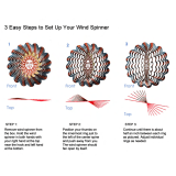
Fig. 1
- Fig. 1 shows the underside of the fuselage and the wing
saddle.
Fig. 2
Installing a brushless motor
- Glue the motor bulkhead 2BR to the doubler 3BR; take
care to line up the holes accurately.
- Offer up the motor to the bulkhead assembly and check
the hole pattern; carry out any adjustments required.
- Place the bulkhead assembly in the fuselage and position
it inset by 3-5 mm all round (according to the propeller
coupling you want to use). Glue the parts together.
Fig. 3
- Before carrying out the next stage please read the instruc-
tions supplied with the motor and the speed controller.
- Locate the motor cables attached to the speed controller
and fit small pieces of heat-shrink sleeve on them.
- Solder the motor and controller cables together, and insu-
late each soldered joint with a heat-shrink sleeve.
- Locate the battery leads attached to the speed controller,
and fit the appropriate connector “S” (matching the flight
battery you intend to use) to them.
- Select the M3 retaining screws for the motor, and check
carefully that they are the correct length - they must not
intrude too far into the motor case.
- Fit the motor and secure it using the 2-4 screws.
Fig. 4
Installing a brushed motor
-
Glue the motor bulkhead 4B to the doubler 5B with the
edges flush all round.
-
Place the bulkhead assembly in the fuselage and position
it inset by 8 mm all round.
Note that the opening for the
motor must be at the bottom.
Glue the parts together.
Bild 1
- Bild 1 zeigt den Rumpf von unten mit dem
Tragflächenausschnitt.
Bild 2
Einbau eines Brushless Motors
- Den Motorspant 2BR so mit der Aufdopplung 3BR
verkleben, dass die Bohrungen deckungsgleich aufeinan-
der liegen.
- Vorgesehenen Motor probeweise einsetzen und Lochbild
von Motor und Spant vergleichen. Falls erforderlich
nacharbeiten.
- Motorspant einsetzen, rundum mit einem Rand von 3-5
mm (je nach vorgesehenem Luftschraubenmitnehmer) zum
Rumpfkopf ausrichten und verkleben.
Bild 3
- Bei den folgenden Arbeiten die Anleitungen beachten, die
dem Motor bzw. dem Regler beigefügt sind.
- Motorkabel des Reglers mit Schrumpfschlauchstücken
versehen.
- Die Anschlüsse von Motor und Regler miteinander ver-
löten. Lötstellen mit Schrumpfschlauch isolieren.
- Am Akkukabel des Reglers eine zum vorgesehenen Akku
passende Steckverbindung “S” anbringen.
- Bei der Auswahl der Gewindeschrauben M 3 für den Motor
die Einschraubtiefe im Motorgehäuse beachten.
- Motor einsetzen und mit 2-4 Schrauben befestigen.
Bild 4
Einbau eines Bürstenmotors
- Motorspant 4B und Aufdopplung 5B deckungsgleich
aufeinanderkleben.
-
Motorspant einsetzen, rundum mit einem Rand von 8 mm
zum Rumpfkopf ausrichten und verkleben.
Der Ausschnitt
für den Motor muss sich unten befinden.

Crazy Boy
8
Bauanleitung, Assembly instructions, Notice de montage
3159
No.
5 6
7 8
8
F
7
100 nF
47 nF
Regler
Speed controller
Variateur de vitesse
100 nF
“S”
Ø 2,2 x 9,5 mm
8
7, 8
“U”
9
10
9

Crazy Boy
9
Bauanleitung, Assembly instructions, Notice de montage
3159
No.
Bild 5
- Den Bürsten-Motor entstören. Dazu die Kondensatoren
100 nF jeweils mit einem Beinchen an das Gehäuse löten,
welches dazu blankzufeilen ist. Zweites Beinchen mit
Isolierschlauch an die Motorpole stecken. Die Beinchen
des Kondensators 47 nF mit Isolierschlauch versehen
und ebenfalls an die Motorpole stecken.
- Ferritkern "F" 1x durch das Motoranschlußkabel des
Reglers schlingen. Das Kabel an die Motorpole löten, die
Kondensatoren werden dabei mitverlötet.
- Das Stecksystem anbringen. Auf richtige Polarität acht-
en. Regleranleitung beachten.
- Motorwelle mit Schleifpapier in Längsrichtung aufrauhen.
- Etwas Loctite in die Bohrung des Ritzels träufeln. Das
Ritzel hochkant auf den Arbeitstisch legen und
Motorwelle einpressen. Dabei von hinten auf die
Motorwelle drücken. Die Welle muß vorn bündig mit dem
Ritzel abschließen.
- Innenzahnrad und Getriebewelle gut einfetten.
- Die Scheibe “U” als Zwischenlage einlegen und das
Getriebegehäuse auf den Motor stecken.
Bild 6
- Antrieb von vorn einschieben. Löcher bohren, Antrieb mit
Blechschrauben Ø 2,2 x 9,5 mm befestigen.
Anschlußkabel nach hinten in den Rumpf führen.
Bild 7
- Den Keil 6 vom vorderen Hauptspant 7 abtrennen.
- Die Halbspanten 8 beidseitig auf den Spant 7 aufkleben.
- Die Öffnung für das Hauptfahrwerk nach Markierung
ausschneiden.
- Spant 7 in den Rumpf setzen, ausrichten und verkleben.
Dabei die Öffnung für das Hauptfahrwerk beachten.
Bild 8
- Längsleisten 9 und hinteren Hauptspant 10 gemeinsam
einsetzen und ausrichten.
Nur die Längsleisten im
Rumpf verkleben.
Fig. 5
- The next stage is to fit the suppressor capacitors to the
brushed motor. Solder one pin of one 100 nF capacitor to the
motor can. Fit an insulating sleeve on the other pin, and
thread it through one motor terminal; file the motor can per-
fectly clean before soldering. Repeat the procedure with the
second 100 nF capacitor and the other motor terminal. Fit
insulating sleeves on both pins of the 47 nF capacitor, and
solder it across the motor terminals as a bridge.
- Wind the motor cables attached to the speed controller
through the ferrite ring “F” for one complete turn as shown.
Solder the wires to the motor terminals, soldering the capac-
itors in place at the same time.
- Attach the connectors, taking great care to maintain correct
polarity. Read the speed controller instructions if you are not
sure of this.
- Rub the motor shaft in the axial direction with abrasive paper.
- Apply a little Loctite to the inside of the pinion bore. Place the
pinion flat on the workbench, hole uppermost, and press the
motor shaft into it, pressing on the other end of the shaft; the
shaft should end flush with the pinion.
- Thoroughly grease the internal-tooth gear and the gearbox
shaft.
- Position the spacer disc “U” as shown, and fit the gearbox
housing on the motor.
Fig. 6
- Fit the motor assembly into the nose bulkhead from the front;
mark and drill the holes for the retaining screws. Attach the
motor using the 2.2 Ø x 9.5 mm self-tapping screws sup-
plied, and run the motor leads back into the fuselage.
Fig. 7
- Cut the wedge 6 from the underside of the front main former
7 to create a recess for the main undercarriage.
- Glue the half-formers 8 on both sides of the former 7.
- Cut out the slot in the underside of the fuselage for the main
undercarriage unit, as shown in the drawing.
- Place the former 7 in the fuselage, align it carefully and glue
it in place. Make sure that the slot for the main undercar-
riage unit lines up corr
ectly with the recess in the former.
Fig. 8
-
Fit the stringers 9 and the r
ear main former 10 at the same
time, and align them car
efully
.
Glue the stringers to the
fuselage, but don’
t glue the former at this stage.
fig. 5
- Antiparasiter le moteur à balais. Pour ce faire, souder sys-
tématiquement une broche des condensateurs 100 nF au
carter du moteur qui aura préalablement été limé. Souder
la seconde broche des condensateurs après les avoir
isolées avec des morceaux de gaine thermorétractable
aux pôles du moteur.
- Disposer le noyau de ferrite "F" 1x au travers du cordon de
connexion du moteur sur le variateur. Souder le cordon aux
pôles du moteur en soudant simultanément les broches de
condensateur.
- Mettre le système de connexion en place. Observer la
polarité des brins.
Observer les instructions fournies par la notice accompa-
gnant le variateur.
- Poncer l’arbre du moteur longitudinalement avec du papi-
er de verre.
- Verser une goutte de Loctite dabs l’alésage du pignon.
Installer le pignon debout sur un chantier plan et engager
l’arbre du moteur en appliquant une forte pression. L’arbre
doit se trouver à fleur à l’avant avec le pignon.
- Bien graisser la roue dentée intérieure et l’arbre d’en-
grenage.
- Intercaler la rondelle”U” et planter le carter d’engrenage
sur le moteur.
fig. 6
- Engager l’entraînement par l’avant. Percer les trous, fixer
l’entraînement à l’aide des vis autotaraudeuses Ø 2,2 x 9,5
mm.
Amener le cordon de connexion vers l’arrière dans le fuse-
lage.
fig. 7
- Désolidariser le coin 6 du couple principal avant 7.
- Coller e demi-couple 8 de chaque côté sur le couple 7.
- Découper le dégagement de l’atterrisseur principal en
fonction des repères.
- Installer le couple 7 dans le fuselage, l’aligner et le coller.
Ce faisant, tenir compte du dégagement destiné à l’atter-
risseur principal.
fig. 8
- Mettre les longerons 9 et le couple principal arrière 10 en
place simultanément et les aligner.
Ne coller que les
longerons dans le fuselage.

Crazy Boy
10
Bauanleitung, Assembly instructions, Notice de montage
3159
No.
9 10
11 12
„R“
15
16
9
16
„SP“
10
11
10
11
7
Ø 1 mm
Ø 1 mm
12
13
14
„R“
„SP“
12
13
15
14
12, 13, 16
14, 15, 16
90°
3 mm
„D“
„D“
„R“

Crazy Boy
11
Bauanleitung, Assembly instructions, Notice de montage
3159
No.
Bild 9
- RC-Platte 11 so in den Rumpf setzen, dass sie in den
Aussparungen der Spanten 7 und 10 liegt. Spant 10 dazu
entsprechend verschieben. Alle Teile zueinander ausricht-
en und verkleben.
Bild 10
- Höhen- und Seitenruder 12, 14 von den Leitwerken 13 und
15 abtrennen. Spalte „SP“ anschleifen. Über die Kante
des Höhenleitwerks einen Streifen Klebeband als
Ruderscharnier „R“ kleben. Ruder umklappen und auf der
Unterseite einen zweiten Streifen Klebeband anbringen.
- Beim Seitenruder/Seitenleitwerk Klebeband beidseitig
anbringen. Die Ruder mehrfach hin- und herbewegen, um
die Leichtgängigkeit zu gewährleisten.
Bild 11
- Gemäß Markierungen Schlitze für die Ruderhörner 16 in
den Rudern einschneiden.
- Ruderhörner 16 mit 1 mm bohren und in die Schlitze der
Ruder 12 und 14 einkleben.
Bild 12
- Schlitz für das Seitenleitwerk im Rumpfende nach
Markierungen austrennen. Ebenso die Durchbrüche “D”
für die Gestänge beidseitig ausarbeiten.
- Den Rumpf auf die Tragfläche setzen. Höhenleitwerk par-
allel fluchtend zur Tragfläche und mittig auf das
Rumpfende kleben.
- Seitenleitwerk rechtwinklig zum Höhenleitwerk aufkleben.
3 mm Abstand zum Höhenleitwerk einhalten.
Fig. 9
- Place the RC plate 11 in the fuselage, and engage the lugs
in the notches of the formers 7 and 10, adjusting the posi-
tion of the former 10 accordingly. Check that everything fits
as shown, then glue the parts together and to the fuselage.
Fig. 10
- Separate the elevator 12 from the tailplane 13, and the rud-
der 14 from the fin 15. Sand the hinge lines “SP” to the
sections shown. Apply a strip of adhesive tape on the top
surface of the trailing edge of the tailplane and the leading
edge of the elevator to act as the elevator hinge “R”. Fold
the elevator “up and over”, and apply a second strip of
tape on the underside.
- Apply the hinge tape on both sides of the fin and rudder as
shown. Move the control surfaces repeatedly to and fro to
satisfy yourself that they move smoothly and freely.
Fig. 11
- Cut slots at the marked points in the control surfaces to
accept the horns 16.
- Drill 1 mm Ø holes in the horns for the pushrods, and glue
them in the slots in the elevator 12 and rudder 14.
Fig. 12
- Cut the slot in the tail end of the fuselage to accept the fin,
working along the marked lines. At the same time cut the
slots “D” for the pushrods on both sides of the fuselage.
- Place the fuselage on the wing. Set the tailplane parallel to
the wing as seen from the nose, and glue it to the tail end
of the fuselage. Check that the tailplane is exactly central
when viewed fr
om above.
-
Glue the fin on the tailplane, setting it exactly at right-
angles. Note that the rudder must have 3 mm clearance
above the tailplane.
fig. 9
- Installer la platine de radiocommande 11 dans le fuselage
de telle sorte qu’elle s’engage dans les dégagements des
couples 7 et 10. Déplacer le couple 10 en conséquence.
Aligner tous les éléments les uns par rapport aux autres et
les coller.
fig. 10
- Détacher la gouverne de profondeur et la gouverne de
direction 12, 14 des plans fixes 13 et 15. Poncer le joint
“SP”. Coller une bande de ruban adhésif sur l’arête du sta-
bilisateur, elle fera office de charnière “R” de gouverne.
Rabattre la gouverne et sur son intrados, appliquer un sec-
ond morceau de ruban adhésif.
- Appliquer des morceaux de ruban adhésif de chaque côté
sur l’ensemble gouverne de direction /dérive. Déplacer les
gouvernes plusieurs fois dans les deux sens de débatte-
ment afin d’assurer leur souplesse.
fig. 11
- En fonction des repères, entailler les fentes des guignols
16 dans les gouvernes.
- Percer les guignols 16 avec une mèche de 1 mm et les
coller dans les fentes des gouvernes 12 et 14.
fig. 12
- Détacher la fente de la dérive dans la queue du fuselage en
fonction des repères. Réaliser également de chaque côté
les passages ”D” destinés aux tringles.
- Installe le fuselage sur l’aile. Coller le stabilisateur et cen
-
tre de la queue du fuselage parfaitement parallèle à l’aile.
- Coller le dérive perpendiculairement par rapport au stabil-
isateur.
Observer l’écart de 3 mm par rapport au stabilisateur.

Crazy Boy
12
Bauanleitung, Assembly instructions, Notice de montage
3159
No.
13 14
15 16
11
17
17
18
18
90°
90°
19
17, 18
19
16
20
21
6
22

Crazy Boy
13
Bauanleitung, Assembly instructions, Notice de montage
3159
No.
Bild 13
- Die Servohebel von den Servos abnehmen.
- Servos in die RC-Platte 11 einsetzen und mit Foam Speed
sichern. Kabel nach vorn führen.
Bild 14
- Seiten- und Höhenrudergestänge 17 und 18 in die Schlitze
am Rumpfheck einschieben und in den Servohebeln ein-
hängen.
- Zur Sicherung ein kurzes Stück Kunststoffrohr 19 auf das
Ende schieben und mit einem Tropfen Sekundenkleber
sichern.
- Servos mit der Fernsteuerung in Neutralstellung bringen.
- Hebel so aufstecken, dass sie mit den Gestängen jeweils
einen Winkel von 90° bilden und mit den
Servohebelschrauben sichern.
Bild 15
- Beide Ruder genau in Mittelstellung bringen und fixieren.
Gestänge genau über der Bohrung des jeweiligen
Ruderhorns markieren und abwinkeln.
- Enden in den Ruderhörnern einhängen.
- Leichtgängigen Lauf der Gestänge prüfen. Falls erforder-
lich, die Durchbrüche am Rumpfende nacharbeiten.
- Gestängeenden an den Ruderhörnern mit Kunststoffrohr-
Abschnitten sichern. Überstand abtrennen.
- Je nach Servohöhe gegebenenfalls die Schlitze für die
Führungsröhrchen im Hauptspant 10 ausfeilen.
- Führungsröhrchen am Hauptspant 10 und am Rumpfende
mit Klebstoff fixieren.
Bild 16
- Hauptfahrwerk 20 parallel zum Höhenleitwerk ausrichten
und Keil 6 mit Foam Speed einkleben.
-
Die Halbschalen 21 für die Räder zusammenkleben.
- Räder auf Ø 1,5 mm aufbohren.
- Räder mit innen und außen auf das Hauptfahrwerk
geschobenen Sicherungsclipsen 22 drehbar fixieren.
Fig. 13
- Remove the output levers from the servos.
- Place the servos in the openings in the RC plate 11, and
secure each with two drops of Foam Speed. Run the servo
leads forward as shown.
Fig. 14
- Slip the rudder pushrod 17 and the elevator pushrod 18
through the slots in the tail end of the fuselage, and connect
them to the servo output arms.
- Push a short piece of plastic sleeve 19 onto the angled end
of the pushrod, and secure it with a tiny drop of cyano.
- Set the servos to neutral (centre) from the transmitter.
- Fit the output arms on the servos in such a way that they
form an angle of 90° to the pushrods. Secure the output
arms with the output screws.
Fig. 15
- Set the rudder and elevator to centre and tape them in that
position. Mark the exact point where the pushrods cross
the holes in the control surface horns, then bend the end at
90° at the marked point.
- Connect the angled ends to the rudder and elevator horns.
- Check that the linkages work smoothly and freely; adjust
the slots in the tail end of the fuselage if necessary.
- Secure the pushrod ends at the horns using short pieces of
plastic sleeve, as described earlier, and cut off the excess
pushrod length.
- If necessary, file out the slots for the guide tubes in the main
former 10 to match the level of the servo output arms.
- Glue the guide tubes to the main former 10 and the slots in
the tail end of the fuselage.
Fig. 16
- Insert the main undercarriage unit 10, and set the wheel
axles parallel to the tailplane. Fit the wedge 6, and glue the
parts together using Foam Speed.
- Glue together the shells 21 to form the main wheels.
- Drill out the completed wheels to 1.5 mm Ø.
- Fit the wheels on the main undercarriage axles and secure
them by pushing the wheel retainers 22 onto the wire.
Check that the wheels rotate freely.
fig. 13
- Retirer les palonniers des servos.
- Installer les servos dans la platine de radiocommande 11
et les fixer avec le produit Foam Speed. Amener les cor-
dons vers l’avant.
fig. 14
- Glisser la tringle de direction et la tringle de gouverne de
profondeur 17 et 18 dans les fentes de la queue du fuse-
lage et les accrocher aux palonniers des servos.
- Pour leur fixation, glisser un morceau court de tube en
plastique 19 sur l’extrémité et l’y fixer avec une goutte de
colle cyanoacrylate.
- Amener les servos au neutre à l’aide de l’ensemble de
radiocommande.
- Mettre les palonniers de servo en place de telle sorte qu’ils
constituent avec les tringles un angle de 90° et les fixer
avec les vis des servos.
fig. 15
- Amener les deux gouvernes exactement en position médi-
ane et les fixer.
Appliquer un repère sur les tringles exactement au niveau
de l’alésage du guignol approprié et les cintrer.
- Accrocher les extrémités dans les guignols.
- Contrôler la souplesse de déplacement des tringles et, si
nécessaire, retravailler les passages de tringle à l’extrémité
du fuselage.
- Fixer les extrémités des tringles aux guignols avec des
morceaux de tube en plastique. Détacher les saillies.
- En fonction de la hauteur des servos, si nécessaire, limer
les fentes des tubes-guides dans le couple principal 10.
- Fixer les tubes-guides au couple principal 10 et à la queue
du fuselage à l’aide de colle.
fig. 16
- Aligner l’atterrisseur principal 20 parallèlement au stabil
-
isateur et coller le coin 6 avec le produit Foam Speed.
- Coller ensemble les demi-coquilles 21 des roues.
- Porter les alésages de roues à Ø 1,5 mm avec une mèche
appropriée.
- Fixer les roues à l’intérieur et à l’extérieur sur l’ atterrisseur
principal à l’aide des circlips 22 mise en place en veillant à
ce qu’elles tournent avec souplesse.

Crazy Boy
14
Bauanleitung, Assembly instructions, Notice de montage
3159
No.
17 18
19 20
24
23
25
“R”
“R”
26
28
27
27

Crazy Boy
15
Bauanleitung, Assembly instructions, Notice de montage
3159
No.
Bild 17
- Den Stützspant 23 mit dem Hecksporn 24 verkleben.
Schlitz im Rumpfheck einschneiden, Einheit einkleben.
Bild 18
- Die Querruder 25 einseitig über die ganze Länge gleich-
mäßig anschrägen.
- Ruder an die Tragfläche 26 ansetzen und mit Tesastreifen
als Ruderscharnier “R” von oben und unten über die ganze
Länge befestigen.
Bild 19
- Die Servorahmen 27 auflegen und mit Tesastreifen fixieren,
noch nicht verkleben.
- Servo-Ausschnitte innen anzeichnen.
Bild 20
- Servoschächte für die Servos nach angezeichneten
Markierungen austrennen.
-
Die Randverstärkung 28 auf die Tragflächenunterseite
kleben.
Fig. 17
- Glue the support 23 to the tailskid 24. Cut a slot for the
skid assembly in the tail end of the fuselage, and glue the
assembly in it.
Fig. 18
- Bevel the leading edge of the ailerons as shown in the
cross-section. Take care to keep the hinge line straight,
and the bevel angle constant.
- Offer up one aileron to the wing 26, and apply a full-length
tape hinge “R” using Tesa tape or similar to the top and
bottom of the hinge axis.
Fig. 19
- Place the servo frames 27 on the wing and tape them in
place; don’t glue them at this stage.
- Mark the servo openings on the wing using the frames as
a template.
Fig. 20
- Cut out the recesses for the servos, working along the
marked lines.
-
Glue the trailing edge doubler 28 on the underside of the
wing as shown.
fig. 17
- Coller le couple d'étai 23 à l’ éperon de queue 24.
Entailler la fente dans la queue et coller l’unité.
fig. 18
- Biaiser les ailerons 25 d’un côté sur toute la longueur de
manière homogène.
- Installer les ailerons sur l’aile 26 et les fixer avec des
morceaux de ruban adhésif ”R”, faisant office de charnière
sur l’intrados et sur l’extrados, sur toute leur longueur.
fig. 19
- Mettre l’encadrement de servo 27 en place et le fixer avec
des morceaux de ruban adhésif, sans coller pour l’instant.
- Marquer les dégagement des servos à l’intérieur.
fig. 20
- Détacher les logements de servo en fonction des r
epères
appliqués.
- Coller les renforts de bordure 28 sur l’intrados de l’aile.

Crazy Boy
16
Bauanleitung, Assembly instructions, Notice de montage
3159
No.
21
22
23 24
29
29
Ø 1 mm
30
30
Ø 10 mm
31
Ø 3 mm
Ø 3 mm
32
31

Crazy Boy
17
Bauanleitung, Assembly instructions, Notice de montage
3159
No.
Bild 21
- Servohebel abnehmen, Servos mit der Fernsteuerung in
Neutralstellung bringen.
- Servohebel bearbeiten und spiegelbildlich auf die Servos
stecken.
- Hebel mit Servohebelschrauben sichern.
- Servos einsetzen.
Bild 22
- Ruderhörner 29 mit Ø 1 mm bohren.
- Ruderhörner und Gestänge 30 einbauen, Gestängeenden
mit Kunststoffröhrchen 31 sichern.
- Servos mit Rahmen verschieben, bis sich die Querruder
beide in Mittelstellung befinden. In dieser Position die
Servorahmen auf der Tragfläche verkleben.
- Servos mit Schrauben oder Foam Speed fixieren.
Bild 23
- Auf der Tragflächen-Oberseite ein Loch von ca. Ø 10 mm
nach Markierung einschneiden und die Kabel der
Querruderservos nach außen führen.
Bild 24
-
Löcher Ø 3 mm nach Markierungen im Rumpf durch-
stechen. Dübel 32 einschieben, mittig ausrichten und
verkleben.
Fig. 21
- Remove the aileron servo output levers and set the servos
to centre from the transmitter.
- Cut down the servo output arms as shown, and fit them on
the servos in a mirror-image arrangement (both arms fac-
ing the centre).
- Secure the output arms using the servo output screws.
- Place the aileron servos in the servo frames.
Fig. 22
- Drill 1 mm Ø holes in the aileron horns 29.
- Install the horns and the pushrods 30, and secure the
pushrod ends with short pieces of plastic sleeve 31.
- Adjust the position of the servos and the servo frames until
both ailerons are at neutral (centre). In this position glue the
servo frames to the wing.
- Check alignment once more, then fix the servos to the
frames using screws or a little Foam Speed.
Fig. 23
- Cut a hole about 10 mm Ø at the marked position in the
top of the wing. Thread the aileron servo cables through
the hole and out of the wing.
Fig. 24
-
Pierce 3 mm Ø holes at the marked points in the fuselage.
Slide the wing dowels 32 thr
ough the holes, set them cen-
tral, and glue them to the fuselage.
fig. 21
- Retirer le palonnier du servo, amener le servo au neutre à
l’aide de l’ensemble de radiocommande.
- Travailler les palonniers de servo et installer les palonnier
symétriquement sur les servos.
- Fixer les palonniers à l’aide des vis de servo.
- Mettre les servos en place.
fig. 22
- Percer les guignols 29 avec une mèche de Ø 1 mm.
- Monter les guignols et la tringlerie 30, fixer les extrémités
de tringle à laide de tubes en plastique 31.
- Décaler les servos dans leur châssis jusqu’à ce que les
deux ailerons se trouvent en position médiane. Dans cette
position, coller les encadrements de servo sur l’aile.
- Fixer les servos avec des vis ou du produit Foam Speed.
fig. 23
- Sur l’extrados de l’aile, entailler un trou d’approx. Ø 10 mm
en fonction du repère et amener les cordons des servos
d’aileron vers l’extérieur.
fig. 24
-
T
ranspercer les trous de Ø 3 mm en fonction des repères
dans le fuselage.
Mettr
e les chevilles 32 en place, les aligner et les coller
.

Crazy Boy
18
Bauanleitung, Assembly instructions, Notice de montage
3159
No.
25 26
27 28
33
33
90°
34
35
35
36
37
37
10 mm
1 mm
Ø 1,5 mm
34 - 37
38, Ø 2,2 x 6,5
4 x
35 - 37

Crazy Boy
19
Bauanleitung, Assembly instructions, Notice de montage
3159
No.
Bild 25
- Die Tragfläche probeweise aufsetzen und mit je 2 über
Kreuz gespannten Gummiringen 33 befestigen.
Bild 26
- Spinner 34 und Spinner-Rückwand 35 nach Markierungen
austrennen. Bei der Rückwand muß ein umlaufender Rand
von ca 1 mm stehen bleiben, auf welchem der Spinner
später aufliegt.
- Rückwandboden 36 in die Rückwand einpassen und ein-
kleben.
- Die Bohrung zur Befestigung des Spinners zunächst mit
6mm
zentrisch ausarbeiten.
- Vier 10 mm Leistenstücke 37 zuschneiden und auf die
Spinner-Rückwand kleben.
Bild 27
- Den Spinner auf die Rückwand setzen. Löcher Ø 1,5 mm
durch Spinner und Leistenstücke bohren. Nur im Spinner
die Löcher auf Ø 2 mm aufbohren.
- Spinner erneut aufsetzen. Überstehenden Rand der
Rückwand zum Spinner verschleifen.
- Ausschnitte für die vorgesehene Luftschraube ausarbeit-
en.
Bild 28
Montage von Luftschraube und Spinner auf einem
Direktantrieb
- Geeignete Luftschraubenkupplung auswählen. Loch Ø 6
mm in der Spinner-Rückwand entsprechend erweitern.
- Bei der Montage der Teile auf ausreichenden Abstand der
Spinner-Rückwand zum Rumpfkopf achten.
- Spinner mit 4 Blechschrauben 38 befestigen.
Fig. 25
- Place the wing on the fuselage wing saddle, and stretch
two rubber bands 33 diagonally between the dowels to
secure it.
Fig. 26
- Cut out the spinner 34 and the spinner backplate 35 along
the marked lines. Be sure to leave an upstand about 1 mm
high all round the edge of the backplate; the spinner will
rest on this later when assembled
- Trim the backplate base carefully to fit inside the spinner
backplate, and glue the parts together.
- Cut the central hole in the spinner using a 6 mm Ø drill; the
hole must be
exactly central.
- Cut four 10 mm lengths from the strip material to form the
screw-blocks 37, and glue the blocks to the spinner back-
plate.
Fig. 27
- Place the spinner on the backplate, and drill 1.5 mm Ø
holes through the cone and the blocks. Open up the holes
in the spinner only to 2 mm Ø.
- Fit the spinner on the backplate again, and sand back the
projecting upstand of the backplate flush with the spinner
cone.
- Cut out the openings in the spinner cone to clear the pro-
peller blades.
Fig. 28
Fitting the propeller and spinner on a direct-drive motor
- Select a suitable propeller adaptor. Open up the 6 mm Ø
hole in the spinner backplate to the size required to clear
the adaptor.
-
Assemble the parts, taking care to leave adequate clear-
ance between the spinner backplate and the fuselage
nose.
- Attach the spinner using the four self-tapping screws 38.
fig. 25
- Mettre l’aile en place à titre d’essai et la fixer avec systé-
matiquement deux élastiques croisés 33.
fig. 26
- Détacher le cône d’hélice 34 et la paroi arrière du cône
d’hélice 35 en fonction des repères. Sur la paroi arrière doit
subsister une marge de 1 mm approximativement sur tout
le pourtour sur laquelle le cône d’hélice s’appuiera
ultérieurement.
- Ajuster le fond de paroi arrière 36 dans la paroi arrière et l’y
coller.
- Réaliser d’abord l’alésage de fixation du cône d’hélice
centré avec une mèche de 6mm.
- Découper quatre baguettes de 10 mm, 37 et les coller sur
la par
oi arrière du cône d’hélice.
fig. 27
- Installer le cône d’hélice sur la paroi arrière. Percer les
trous de Ø 1,5 mm au travers du cône d’hélice et des
baguettes. Dans le cône d’hélice uniquement, porter les
trous à Ø 2 mm.
- Remettre le cône d’hélice en place. Poncer la saillie arrière
de la paroi arrière par rapport au cône d’hélice.
- Réaliser les dégagements pour l’hélice prévue.
fig. 28
Montage de l’hélice et du cône d’hélice sur un entraîne-
ment direct
- Sélectionner un accouplement d'hélice approprié. Porter le
trou de Ø 6 mm dans la paroi arrière du cône d’hélice à la
taille appropriée.
- Lors du montage des éléments, veiller à observer un écart
suffisant entre la paroi arrière du cône d’hélice et le nez du
fuselage.
- Fixer le cône d’hélice avec 4 vis autotaraudeuses 38.

Crazy Boy
20
Bauanleitung, Assembly instructions, Notice de montage
3159
No.
30
29
32
31
38, Ø 2,2 x 6,5
4 x
35 - 37
50 mm
BR-R
R
BR-M
M
A
A
Rx
Rx
S
S
M
R
A
Rx
S
C.G.
85 mm
BR-M Brushless-Motor
Brushless motor
Moteur sans balais
BR-R Brushless-Regler
Brushless controller
Variateur Brushless
A Akku
Battery
Accu
Rx Empfänger
Receiver
Récepteur
S Servo
M Motor, Moteur
R Regler
Speed controller
Variateur
50 mm
20 mm
20 mm
25 mm
25 mm
/