Page is loading ...

1
TOUCH SCREEN WEATHER CENTER
MODEL WS-3610
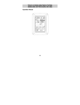
Operation Manual

2
Table of Contents
1 ................... General
2 ................... Important Notes for Operating the Touch Screen
3 ................... To Begin Operation
3.1 ............. Wiring the System
3.2 ............. Power Supply
3.2.1........ Use Batteries for Power
3.2.2........ Use AC Adapter for Power
3.2.3........ Cable Connection
3.3 ............. System Start
3.4 ............. Placement
4 ................... Setting Up
5 ................... Display of stored Min/Max Values and Alarm Value
Settings
6 ................... Radio Controlled WWVB Signal Reception and Clock
7 ................... Weather Tendency
8 ................... Barometric Pressure History Bar Graph
9 ................... Operating and Setting of various Functions
9.1 ............. Air Pressure
10 ................. Operating and Setting the Rain Function
11 ................. Additional Information – Outdoor Temperature Display
12 ................. Additional Information – Wind Display
12.1 ........... Operating and Setting the Wind Direction Alarm
13 ................. Operating and Setting the Backlight, Buzzer and Alarm in
the WIND Section
13.1 ........... EL Backlight
13.2 ........... Buzzer
13.3 ........... Alarm
14 ................. PC Connection
14.1 ........... Data Storage
14.2 ........... Data Recall
14.3 ........... Connections and Software
15 ................. Technical Data
15.1 ........... Outdoor Data
15.2 ........... Data Transmission by 433 MHz Signal
15.3 ........... Data Transmission by Cable
15.4 ........... Indoor Data
15.5 ........... Power Supply
15.6 ........... PC Connection
15.7 ........... Dimensions

3
1 General
The shipping contents of the WS-3610 Touch Screen Weather
Center include a Base Station (Receiver), a Thermo-Hygro
Sensor (433 MHz Transmitter), a Rain Sensor and a Wind
Sensor, the respective Connecting Cables, an AC Adapter and
a CD-ROM with a Package of PC Software for collected
Weather Data.
The Base Station is equipped with a Touch Screen LCD Monitor,
which features a variety of time and weather data via a
comprehensive and interactive menu. The following list
describes the features in order from top to bottom:
• Radio Controlled Time (Time)
• Perpetual Calendar (Date)
• Weather Forecast with Tendency Arrow (Tendency)
• Barometric Pressure and 72 Hour History Bar Graph
(Pressure, Pressure History)
• Indoor Temperature and Humidity (Indoor Temp, Humidity)
• Wind
• Rain (Rain)
• Outdoor Temperature and Humidity (Outdoor Temp,
Humidity)
Additional data can by displayed by certain touch screen field
combinations that are explained later.
Note: When the menu is touched and activated, the “active
menu steps” temporarily replace all of the “standard
indications” as mentioned in the list above.
In addition to the LCD monitor, the WS-3610 has the ability to
transfer all collected time and weather data to a PC via a Com
port connection. The supplied PC software provides complete
sets of history data, data graphing, and webpage update
capabilities.

4
2 Important Notes for Operating the Touch Screen
(Generally Applicable)
• All actions and functions of the Weather Center begin by
slightly touching, not pressing, the Touch Screen.
• The switchable areas appear with a star (٭) symbol in the
bottom section of the LCD or above the corresponding
values.
• The following selections in the bottom section of the LCD are
used to set any function, value, or unit within any mode:
٭ON٭ or ٭OFF٭, ٭UP٭ or ٭DOWN٭, or by directly selecting
the unit.
• When setting any function, value, or unit, ٭NEXT٭ will
advance the screen to the next menu option; ٭EXIT٭ will exit
the menu and return to the normal display mode.
• Every programming step activated by touching a switchable
area on the screen is acknowledged by an audible beep
when the buzzer option is switched to “ON”.
• During any menu operation, if no active area is touched for
20 seconds, the menu is automatically deactivated and the
screen will return to the normal display mode.
3 To Begin Operation
To begin it is necessary to decide whether to use AC power
(adapter included) or batteries to operate the system. Either
method will ensure a connection to the Thermo-Hygro Sensor
and Base Station by cable or by a 433 MHz wireless radio signal.
Note: When first setting up the Weather Center, it is
important to temporarily set up the entire system in
close proximity on a table or counter top as you intend
to use the system (wired or wireless). This step serves
as a test to ensure that all components function
correctly prior to final installation.

5
3.1 Wiring the System
Connect the Rain Sensor and Wind sensor cables to their
respectively marked jacks in the Thermo-Hygro sensor BEFORE
powering up the Base Station or the Thermo-Hygro Sensor.
The Thermo-Hygro Sensor and Base Station can be
directly connected via cable if the wireless 433 MHz
radio transmission is not desired, and/or data
transmission free of localized radio interference is an
important factor.
3.2 Power Supply
Power can be supplied to the Weather Center using batteries or
the AC adapter. In the case that the AC adapter is used, it will
provide all required power to the system if the Base Station and
Thermo-Hygro Sensor are wired directly together.
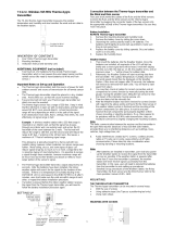
3.2.1 Use Batteries for Power:
- First insert two Type C alkaline 1.5 V batteries into the
battery compartment of the Thermo-Hygro-Sensor.
- Immediately after, insert three Type AA alkaline 1.5 V
batteries into the battery compartment of the Touch Screen
Base Station.
3.2.2 Use AC Adapter for Power:
- First insert two Type C alkaline 1.5 V batteries into the
battery compartment of the Thermo-Hygro-Sensor.
- Immediately after, connect the AC adapter to the Base
Station, and then plug it into an AC outlet.
- When the AC adapter is used, batteries may also be placed
in the Base Station to serve as a backup power supply if
there is a power outage.
Note: In either case, it is important to observe this order of
succession because the Sensor will send an identification
code that must be received and stored by the Base Station
within the first few minutes of operation.

6
It is also important to allow the Base Station to operate for
at least 15 minutes prior to touching any part of the Touch
Screen display.
Once these steps have been completed, the correct operation of
the entire weather system is ensured.
3.2.3 Cable Connection:
When operating a completely wired system, (cable connection
between Base Station and Thermo-Hygro, as well as a
connection between the individual sensors) power will be
supplied not only to the Base Station but to the all of the sensors
as well when the AC adapter is used.
Note: Operating the system directly wired while powering the
Base Station solely by batteries is not recommended due to the
considerably higher power consumption of the wired
configuration. The batteries may however remain in the Base
Station for emergency supply in case of a power failure.
A change from cable operation to 433 MHz radio
transmission or vice versa is possible in any case since
the Base Station will recognize this change and will
automatically switch to the appropriate operating mode.
3.3 System Start
After inserting the batteries or connecting the AC adapter, the
LCD will display all of the digital segments for a few seconds.
Immediately after this the Base Station will enter a test mode
during which all measured and received weather data is cycled
through, updated and displayed for a period of approximately 15
minutes.
During this test mode, the unit will not receive the WWVB time
signal.

7
Note: The test mode is designed so that you may check all of the
cables for correct connection and all of the components for
proper function.
• To manually test the Wind Sensor: manually turn the
wind-gauge, moving the weather-vane.
• To manually test the Rain Sensor: tilt the rain sensor
back and forth in order to hear the impact of the
internally moving seesaw.
• To manually test the Thermo-Hygro: with both the Base
Station and Thermo-Hygro placed next to each other,
compare the INDOOR and OUTDOOR sections of the
LCD to make sure that they both produce similar data
(within the specifications of the units).
After completing the test mode, the Touch Screen Weather
Center will automatically switch to the normal display mode in
order to perform all other settings. At this point the Base Station
will also automatically start searching for the WWVB time signal.
3.4 Placement
Once the Base Station and Sensors have been checked and
validated for correct function as mentioned in 3.3, all the system
components are ready to be permanently mounted.
It is critical to ensure that all components work properly together
at their chosen mounting or standing location. If it appears that
the Base Station is not receiving the wireless 433 MHz radio
transmission, moving the Thermo-Hygro Sensor to a different
location will usually fix the problem.
Note: The radio communication between receiver and
transmitter can reach distances of up to 330 ft providing
that there are no interfering obstacles such as buildings,
trees, vehicles, high voltage lines, or similar obstructions.
If possible, PC monitors, radios, TV sets, and other
sources of radio interference should also be avoided.

8
4 Setting Up:
Note: Because of the default settings already determined by
the manufacturer, it may not be necessary to alter the
basic settings other than Relative Air Pressure (see
further down) If changes to the settings are needed, they
can easily be made if desired.
Touching the screen in the center of the text display within the
bottom two lines of the LCD will enter into the menu shown
below.
Touching the ٭SETUP٭ field will enter the setup mode.
The basic settings can now be performed in the following
successive order:
LCD Contrast
→ Contrast can be set in 8 steps from 0 to 7
(Default is 4).
Time Zone
→ Time Zones can be set in a range from
-12 to +12 hours.
Note: U.S.A. time zones will be displayed (not in hours) but in
the respective time zone abbreviations:
-4 h → ATL (Atlantic Time)
-5 h → EST (Eastern Standard Time)
-6 h → CST (Central Standard Time)
-7 h → MST (Mountain Standard Time)
-8 h → PST (Pacific Standard Time)
-9 h → ALA (Alaska Time)
-10 h → HAW (Hawaiian Time)
(Default is -5 h → EST (Eastern Standard Time).

9
Daylight Saving Time
(DST) → Daylight Saving time can be set
to on or off. The “ON” setting will automatically change the
WWVB Time Display from summer time to wintertime and vice
versa when it is activated. (Default is DST “ON”).
To proceed, touch ٭NEXT٭.
WWVB Radio Controlled Clock
(RCC) → ON/OFF. When the
“OFF” setting is selected, the clock is operates as a normal
Quartz clock (Default is RCC “ON”).
12/24 hour Time Display Format
When 12h format is selected, the hour is shown with « A.M »
between midnight and noon, and « PM » between noon
and midnight. (Default is 12-hour format).
Units
• Temperature (Temp) is displayed in °F or °C (Default is °F).
• Wind Speed (Wind) is displayed in mph, km/h, m/s, knots or
Beaufort (Default is mph).
• Rain Amount (Rain) is displayed in inch or mm
(Default is inch).
• Air Pressure (Press) is displayed in inHg or hPa
(Default is inHg).

10
Relative Air Pressure
(Rel. Pressure) → This should be set
locally to ensure a valid reference for air pressure in regards to
the local height above sea level (Default is 29.91 inHg).
Weather Tendency
(Tendency) → The Weather Tendency
sensitivity has 3 steps of sensitivity: 0.06 inHg, 0.09 inHg, and
0.12 inHg. (Default 0.09 inHg) In most cases the default works
well; however this should be set to 0.06 near the ocean and
0.012 in desert areas.
Storm Warning
(Storm) → Storm Warning sensitivity has 7 steps
of sensitivity: increments of 0.03 inHg from 0.09 inHg to 0.27
inHg, for storm warning display at a decrease of air pressure
over 6 hours (Default 0.18 inHg).
Activate or Deactivate storm warning alarm with ٭ON٭ / ٭OFF٭
(Default is ON).
Relearn Mode
(Relearn Tx) → Allows the WS-3610 to relocate
the outdoor transmitter (for example, after a changing a battery
in the Thermo-Hygro) without the necessity of a complete re-
setup of all system components → Acknowledge with
٭CONFIRM٭.

11
Default Settings (Factory Reset) → Allows the reset of all
settings and/or stored values to the factory default →
Acknowledge with ٭CONFIRM٭.
Once all of the settings have been made, touch ٭EXIT٭ to leave
the basic setup mode.
5 Display of stored Min/Max Values
and Alarm Value Settings
Upon recall, named values will display and flash in their
respective sections.
Min/Max and alarm values are recalled from the menu shown
below which must be activated by touching the Touch Screen in
the center of the text display section (last two lines at the bottom
of the LCD). Touching the *MINMAX* or *ALARMS* field will
display the corresponding values.
The Min/Max values can also be recalled individually by touching
the respective area of the display. Example: Touching the
“Indoor” section of the display will activate the menu shown
below. Min, Max, and Alarm values can then be displayed by
touching the corresponding field.

12
Note: When individual Min/Max values are displayed; the top line
of the LCD screen will automatically display the time and
date that the data was recorded.
The following menu item will appear upon touching the
٭ALARMS٭ field. Low and high alarms are displayed via the
corresponding *LO AL* and *HI AL* fields; the individual values
are displayed in the same manner as individual Min/Max values.
(See above)
At any time the opposite respective menu (MIN/MAX or ALARM)
can be accessed via its corresponding field.
Touching the *EXIT* field at any time will return the LCD to its
normal display.
6 Radio Controlled WWVB Signal Reception and Clock
The NIST (National Institute of Standards and Technology—
Time and Frequency Division) WWVB radio station is located in
Ft. Collins, Colorado. A tower located there transmits the exact
time and date signal continuously throughout the United States
at 60 kHz. The signal can be received up to 2,000 miles away
through the internal antenna in the Base Station.
The WWVB radio station derives its signal from the NIST Atomic
clock in Boulder, Colorado. A team of atomic physicists is
continually measuring every second, of every day, to an
accuracy of ten billionths of a second per day. These physicists
have created an international standard, measuring a second as
9,192,631,770 vibrations of a Cesium-133 atom in a vacuum. For
more information on the atomic clock and WWVB please see the
NIST website at
http://www.boulder.nist.gov/timefreq/stations/wwvb.htm.

13
Due to the nature of the earth’s ionosphere, WWVB signal
reception is very limited during daylight hours. The base station
will search for the signal every night when the reception is the
strongest.
The WWVB Radio Controlled Clock in the Base Station is
normally controlled by the radio signal of the WWVB time code
transmitter and will thus set time and date automatically. Under
bad reception conditions however both time and date can be set
manually:
Setting the Time
To set the time, touch the time display.
Next, touch the ٭TIME٭ field in the bottom section of the LCD.
Set the hours and minutes by touching either ٭UP٭ or ٭DOWN٭.
To leave the mode, touch ٭EXIT٭ or wait for automatic time-out.
Setting the Date
To set the date, touch the date display.

14
Set the year, month and date by touching either ٭UP٭ or
٭DOWN٭.
To leave the mode, touch ٭EXIT٭.
Note: By twice touching the DATE section, the display will toggle
between the following:
• Date in MM.DD.YY format
• Weekday (abbrev.), Date of Day, Month
• Seconds
• Set Alarm Time
Setting the Time Alarm
To set the Time Alarm, first touch the time field. Then touch the
٭ALARM٭ field in the bottom section of the LCD.
Set the hours and minutes for the time alarm.
To leave the mode, touch ٭EXIT٭.
Note: The time alarm is activated or deactivated by touching the
TIME section of the LCD twice. The alarm symbol (((•)))
will show or disappear. To leave the mode, touch ٭EXIT٭
or wait for the automatic time-out.
7 Weather Tendency
Call up the tendency display by touching the weather symbol in
the TENDENCY section.

15
The text fields at the bottom of the LCD will display the weather
condition (with time and date) that corresponds to the presently
displayed weather symbol Sunny, Fair (Cloudy with sunny
intervals) or Rainy.
8 Barometric Pressure History Bar Graph
(Pressure History)
The air pressure history bar graph shows the progress of the
barometric air pressure over a time period of 24 or 72 hours in
the form of a 7-step bar graph. The length of the right-most bar
represents the present air pressure, and the remaining bars to
the left show the progress of the air pressure in regards to the
present air pressure.
Note: The time resolution of the bar graph can be changed from
fine (0 to -24 h) to coarse (0 to -72 h) and back by touching
the PRESSURE HISTORY section once.
9 Operating and Setting of the following Functions:
• Air Pressure (Pressure), Relative and Absolute
• Indoor Temperature (Indoor Temp)
• Indoor Humidity (Indoor Humidity)
• Outdoor Temperature (Outdoor Temp), Wind Chill, Dew
Point
• Outdoor Humidity (Outdoor Humidity)
• Wind Speed, Wind Gust

16
Important Note!
Since operating and settings procedures are identical for all
of the functions mentioned in the list above, you will use the
same process described below for “Air Pressure” to set all
of the functions mentioned in the list above.
9.1 Air Pressure (Pressure)
Example for Activating the Displays of Stored Maximum
Values
Call up the corresponding menu in the bottom section of the LCD
by touching the PRESSURE field.
Start by touching in the bottom section of the LCD.
Note: It is possible to display the stored minimum values
in the bottom section of the LCD in the same
fashion by touching the ٭MIN٭ field.
After touching ٭MAX٭, the stored value is displayed. Proceed by
touching the ٭MAX PRESSURE٭ field.
The displayed value can be reset to the current value by
touching *CONFIRM*. To advance without resetting, touch
٭EXIT٭.
This completes the Example

17

18
Example for Setting of Alarms by means of the HI Alarm
As in the example above, call up the corresponding menu in the
bottom section of the LCD by touching the PRESSURE field.
Proceed by touching ٭ALARM٭ in the section at the bottom of
the LCD.
Proceed with ٭HI AL٭ in the menu section.
Note: Setting of the low alarms is possible from here in
the same fashion by touching the ٭LO AL٭ field.
Set the high alarm value with ٭UP٭ or ٭DOWN٭.
Proceed with ٭ON/OFF٭.
Activate or deactivate the alarm with ٭ON٭ or ٭OFF٭.
Return to normal display by touching ٭EXIT٭.
Note: Activation or deactivation of the alarm (Display or deletion
of the (((•))) symbol) only pertains to the presently
displayed value, in this example it is PRESSURE.
This completes the Example

19
Note: Touching the PRESSURE section twice toggles the
display between Relative (rel) and Absolute (abs) air
pressure.
All setting and display options only pertain to the presently
displayed value.
10 Operating and Setting the Rain Function
Note: Besides the direct setting of the units for the rain amount in
the basic setup procedure, it is possible to toggle between
the following displays by touching the left part of the RAIN
section twice:
• Rain amount for the last hour
• Rain amount for the last 24 hours
• Rain amount for the last week
• Rain amount for the last month
Note: The rain amounts for the last week and the last
month do not represent the amounts collected up to
the present point of time, but to those for the last
complete week or the last complete month.
All setting and display functions pertain only to the
presently displayed value.
Important Note!
Operation and settings of the Rain function are essentially
identical to the ones described in Item 9 above. Therefore a
short description of the minor differences in regards to Item
9 will be a sufficient enough explanation.
• Since it is not necessary to display minimum rain values, the
menu does not offer the item ٭MIN٭ but ٭MAX٭ only to
display the various maximum rain amounts.
• Since no minimum rain values are stored, upon activating
the ٭ALARM٭, the display will immediately proceed to the
high alarm setting as described in section 9 above.

20
Note: The alarm option is only offered during display of the last
hour and last 24-hour rainfall amounts. No exact definition
of alarm time is possible for weekly and monthly rain
amounts; therefore these alarm functions have been
omitted.
• When touching the TOTAL field in the RAIN section, the total
rain amount accumulated since the last deletion is displayed.
This can be erased by touching ٭RAIN TOTAL٭ in the
bottom section of the LCD, followed by ٭CONFIRM٭.
11 Additional Information regarding the Outdoor
Temperature Display (Outdoor Temp)
Note: Touch the OUTDOOR field to toggle the display between
the following:
• Outdoor Temperature (Outdoor Temp)
• Wind Chill
• Dew Point
All setting and display options only pertain to the presently
displayed value.
12 Additional Information regarding the Wind Display
Note: Touch the WIND field to toggle the display between the
following:
• Wind Speed
• Wind Direction (Abbreviations of the compass rose
descriptions)
• Wind Direction (Degrees)
• Wind Gust
All setting and display options only pertain to the presently
displayed value.
/