Page is loading ...

®
http://www.3com.com/
Using the PathBuilder
™
S5xx
Switch
Part No. 09-1868-000
Published November 1999

3Com Corporation
5400 Bayfront Plaza
Santa Clara, California
95052-8145
Copyright ©
3Com Corporation, 1999.
All rights reserved. No part of this documentation may be reproduced
in any form or by any means or used to make any derivative work (such as translation, transformation, or
adaptation) without permission from 3Com Corporation.
3Com Corporation reserves the right to revise this documentation and to make changes in content from time
to time without obligation on the part of 3Com Corporation to provide notification of such revision or change.
3Com Corporation provides this documentation without warranty of any kind, either implied or expressed,
including, but not limited to, the implied warranties of merchantability and fitness for a particular purpose.
3Com may make improvements or changes in the product(s) and/or the program(s) described in this
documentation at any time.
UNITED STATES GOVERNMENT LEGENDS:
If you are a United States government agency, then this documentation and the software described herein are
provided to you subject to the following restricted rights:
For units of the Department of Defense:
Restricted Rights Legend:
Use, duplication, or disclosure by the Government is subject to restrictions as set
forth in subparagraph (c) (1) (ii) for Restricted Rights in Technical Data and Computer Software Clause at 48
C.F.R. 52.227-7013. 3Com Corporation, 5400 Bayfront Plaza, Santa Clara, California 95052-8145.
For civilian agencies:
Restricted Rights Legend:
Use, reproduction, or disclosure is subject to restrictions set forth in subparagraph (a)
through (d) of the Commercial Computer Software - Restricted Rights Clause at 48 C.F.R. 52.227-19 and the
limitations set forth in 3Com Corporation’s standard commercial agreement for the software. Unpublished
rights reserved under the copyright laws of the United States.
If there is any software on removable media described in this documentation, it is furnished under a license
agreement included with the product as a separate document, in the hard copy documentation, or on the
removable media in a directory file named LICENSE.TXT. If you are unable to locate a copy, please contact
3Com and a copy will be provided to you.
Unless otherwise indicated, 3Com registered trademarks are registered in the United States and may or may
not be registered in other countries.
3Com, NETBuilder, NETBuilder II, OfficeConnect, and Transcend are registered trademarks of 3Com
Corporation. 3TECH, PathBuilder, and Total Control are trademarks of 3Com Corporation. 3ComFacts is a
service mark of 3Com Corporation.
CompuServe is a registered trademark of CompuServe, Inc. IBM is a registered trademark of International
Business Machines Corporation. AppleTalk is a registered trademark of Apple Corporation. Banyan and VINES
are registered trademarks of Banyan Systems. UNIX is a registered trademark in the United States and other
countries, licensed exclusively through X/Open Company Limited. XNS is a trademark of Xerox Corporation.
Siemens and EWSD are registered trademarks of Siemens Aktiengesellschaft. AT&T and 5ESS are registered
trademarks of American Telephone and Telegraph. DMS is a registered trademark of Nothern Telecom Limited.
Other brand and product names may be registered trademarks or trademarks of their respective holders.
The software contained in this product may contain encrypted product which may not be exported
or transferred from the U.S. or Canada without an approved U.S. Department of Commerce export
license.
Electromagnetic Compatibility Information
Classes
Various national agencies (in the United States, The Federal Communications Commission (FCC)) govern the
levels of electromagnetic emissions from digital devices. Electromagnetic emissions can interfere with radio
and television transmission. To reduce the risk of harmful interference these agencies have established
requirements for manufacturers of digital devices.
The manufacturer of a digital device must test and label a product to inform an end-user of the maximum
emission level from the product when used in accordance with its instructions. The emission levels
encountered are classified as Class A or Class B. A system that meets the Class A requirement can be
marketed for use in an industrial or a commercial area. A system that meets the more stringent Class B
requirement can be marketed for use in a residential area in addition to an industrial or a commercial area.
The end user is generally held responsible for ensuring that her system is suitable for its environment as stated
in the above paragraph and bears the financial responsibility for correcting any harmful interference.
Modifications
Modifications or changes made to this device, and not approved by 3Com, may void the authority granted by
the FCC, or other such agency, to operate this equipment.

Shielded Cables
Connections between 3Com equipment and other equipment and peripherals must be made using shielded
cables in order to maintain compliance with FCC, and other agency, electromagnetic frequency emissions
limits. This statement does not apply to the 10BASE-T cables.
Federal Communications Commission Notice
This equipment has been tested and found to comply with the limits for a Class B digital device, pursuant to
Part 15 of the FCC rules. These limits are designed to provide reasonable protection against harmful
interference when the equipment is operated in a commercial environment. This equipment generates, uses
and can create radio frequency energy and, if not installed and used inaccordance with the instruction manual,
may cause harmful interference to radio communications. If this equipment does cause harmful interference to
radio or television reception, which can be determined by turning the equipment off and on, the user is
encouraged to try and correct the interference by one or more of the following measures:
Reorient or relocate the receiving antenna.
■
Increase the separation between the equipment and the receiver.
■
Connect the equipment into an outlet on a circuit different from that to which the receiver is
connected.
■
Consult the dealer or an experienced radio/TV technician for help.
In order to meet FCC Class B limits, this equipment must be used only with cables which comply with IEEE
802.3.
The user may find the following booklet prepared by the Federal Communication Commission helpful:
How to Identify and Resolve Radio-TV Interference Problems
This booklet is available from the U.S. Government Printing Office, Washington, DC 20402, Stock No.
004-000-00345-4.
FCC Part 68 Statement
This equipment complies with Part 68 of the Federal Communications Commission (FCC) rules. On the
product is a label that contains the FCC registration number for this device. If requested, this information
must be provided to the telephone company.
This equipment is designed to be connected to the telephone network or premises wiring using a compatible
modular jack which is Part 68 compliant. See installation instructions for details.
If this device causes harm to the telephone network, the telephone company will notify you in advance that
temporary discontinuance of service may be required. The telephone company may request that you
disconnect the equipment until the problem is resolved.
The telephone company may make changes in its facilities, equipment, operations or procedures that could
affect the operation of this equipment. If this happens the telephone company will provide advance notice in
order for you to make necessary modifications to maintain uninterrupted service.
If trouble is experienced with this equipment or for repair or warranty information, please follow the applicable
procedures explained in the "Technical Support" section of this manual.
FCC Registration Number See label on product
Required Connector (USOC) RJ-49
Service Order Code (SOC) 6.OY
Facility Interface Code (FIC) 02IS5
Canadian Notice
The Industry Canada label identifies certified equipment. This certification means that the equipment meets
certain telecommunications network protective, operational, and safety requirements. Industry Canada does
not guarantee the equipment will operate to the users’ satisfaction.
Before installing this equipment, users should ensure that it is permissible to be connected to the facilities of
the local telecommunications company. The equipment must also be installed using an acceptable method of
connection. In some cases, the inside wiring associated with a single line individual service may be extended
by means of a certified connector assembly. The customer should be aware that compliance with the above
conditions may not prevent degradation of service in some situations.

Repairs to certified equipment should be made by an authorized Canadian maintenance facility designated by
the supplier. Any repairs or alterations made by the user to this equipment, or equipment malfunctions, may
give the telecommunications company cause to request the user to disconnect the equipment.
Users should ensure for their own protection that the electrical ground connections of the power utility,
telephone lines, and internal metallic water pipe system, if present, are connected together. This precaution
may be particularly important in rural areas.
CAUTION: Users should not attempt to make electrical ground connections by themselves, but should contact
the appropriate inspection authority or an electrician, as appropriate.
Japanese Notice
CE Notice
Marking by the symbol indicates compliance of this equipment to the EMC
Directive 89/336/EEC, the Low Voltage Directive 73/23/EEC amended by 93/68/EEC and the Telecom Terminal
Equipment and Satellite Earth Stations Directive 98/13/EEC. Such marking is indicative that this equipment
meets or exceeds the following technical standards:
■
EN 55022 - "Limits and Methods of Measurement of Radio Interference Characteristics of Information
Technology Equipment."
■
EN 50082-1 - "Electromagnetic compatibility - Generic immunity standard Part 1: Residential,
commercial, and light industrial."
■
EN60950 (1992) - Safety of information technology equipment, including electrical business equipment.
■
CTR 1 - "Attachment requirements for terminal equipment to be connected to circuit switched data
networks and leased circuits using a CCITT Recommendation X.21 interface, or at an interface
physically, functionally and electrically compatible with CCITT Recommendation X.21 but operating at
any data signalling rate up to, and including, 1 984 kbit/s"
■
CTR 2 - "Attachment requirements for Data Terminal Equipment (DTE) to connect to Packet Switched
Public Data Networks (PSPDNs) for CCITT Recommendation X.25 interfaces at data signalling rates up
to 1 920 kbit/s utilizing interfaces derived from CCITT Recommendations X.21 and X.21 bis"
■
CTR 4 - "Integrated Services Digital Network (ISDN); Attachment requirements for terminal equipment
to connect to an ISDN using ISDN primary rate access"
■
CTR 12 - "Open Network Provision (ONP) technical requirements; 2 048 kbit/s digital unstructured
leased line (D2048U) Attchment requirements for terminal equipment"
■
CTR 13 - "2048 kbit/s digital structured leased lines (D2048S); Attachment requirements for terminal
equipment interface"
■
CTR 24 - "34 Mbit/s digital unstructured and structured leased lines (D34U and D34S); Attachment
requirements for terminal equipment interface"
■
A "Declaration of Conformity" in accordance with the above standards has been made and is on file at
3Com Corporation.
56

C
ONTENTS
A
BOUT
T
HIS
G
UIDE
Conventions 13
Year 2000 Compliance 14
O
VERVIEW
OF
THE
P
ATH
B
UILDER
S
WITCH
Using the PathBuilder Switch in Your Network 15
Using Ethernet LAN Interfaces 15
Using Flex-WAN Serial and Ultra-WAN CSU/DSU Interfaces 16
Using ATM Interfaces 16
Telco Services 17
Using PPP on Dial-Up and Leased Lines 18
Using Packet-Switched Network Services 18
IBM Legacy Networks 18
Hardware Features 20
Back and Front Panels 20
Hardware Interrupt Switch 23
Reset Button 23
I
NSTALLING
THE
H
ARDWARE
Required Equipment 25
Mounting the Switch 26
Environmental Requirements 26
Mounting Kit 26
Installing on a Tabletop 27
Stacking with Brackets 27
Installing in a Rack 28
Cabling the Connectors 29
Cabling the LAN Connectors 29
Cabling the Flex-WAN Serial Connectors 30

Cabling the Ultra-WAN CSU/DSU Connectors 30
Cabling the HSSI T3/E3 Connectors 31
Cabling the Coax T3/E3 (BNC) Connectors 31
Cabling the ATM Connectors 32
Cabling the ATM OC3 Connectors 32
Cabling the ATM Coax (DS3/E3) Connectors 33
Attaching a Redundant Power System 33
Connecting a PC, Terminal, or Modem 34
Shutting Down 35
L
OGGING
O
N
AND
P
ERFORMING
A
DMINISTRATIVE
T
ASKS
Starting the System 37
Verifying Successful Startup 38
Logging On to the System 39
Configuring an IP Address 39
Choosing the User Interface 40
Deciding Which Interface to Use 40
Using Menus 41
Using the Command-line Interface 42
Using Web Link 43
Using Transcend 43
Changing the Root Password 43
Changing the Default Console Port Baud Rate 44
Adding User Accounts 45
Setting the Time and Date 45
Setting System Information 46
Setting Up Security Access 46
B
ASIC
C
ONFIGURATION
OF
P
ORTS
, P
ATHS
,
AND
C
ONNECTORS
Paths, Ports, and Connectors 49
Multiple Port and Path Bindings 50
Dynamic Paths 50
Virtual Ports 50
Port/Path Services and Syntax 51
Connector Services and Syntax for Ultra-WAN Interfaces 51
Path and Port Numbering 52

Model S500 52
Model S580 52
Model S590 53
Model S593/S595 53
Model S598 and S599 54
Model S574 and S578 54
Configuring Ethernet Paths and Ports 55
Configuring Flex-WAN Serial Interfaces with DCEs 55
Configuring Flex-WAN Serial Interfaces with DTEs 56
Configuring the Ultra-WAN CSU/DSU Interfaces 56
Configuring a CSU/DSU Interface for ISDN PRI Dial Service 57
Configuring a CSU/DSU Interface for Single Path, Unstructured
Service 59
Configuring a CSU/DSU Interface for Multiple Path, Channelized
Service 60
Configuring the High-Speed T3 Interface 62
Configuring the ATM Interfaces 62
Where To Go From Here 65
C
ONFIGURING
AND
M
ONITORING
V
IRTUAL
P
RIVATE
N
ETWORKS
Remote Access Alternatives 67
Using Tunnels 67
ISP to Central Site Tunneling 68
Remote User to Central Site Tunneling 68
Creating a VPN for Individual Remote Users 68
Example 1 69
Example 2 70
Creating a VPN for a Remote Office 71
On the Remote Office OfficeConnect Bridge/Router 72
On the Central Site PathBuilder Switch 73
Monitoring VPN Performance 73
Web Link Health Monitor 73
Secure VPN Manager 73
InfoVista 74

S
ERIAL
DEVICES
Dial Serial Device Requirements 75
T
ECHNICAL
S
UPPORT
Online Technical Services 77
World Wide Web Site 77
3Com Knowledgebase Web Services 77
3Com FTP Site 78
3Com Bulletin Board Service 78
Access by Analog Modem 78
Access by Digital Modem 79
3Com Facts Automated Fax Service 79
Support from Your Network Supplier 79
Support from 3Com 79
Returning Products for Repair 81
C
ONNECTORS
AND
C
ABLES
Console Connector and Cables 83
PC Cable 83
Terminal Cable 84
Modem Cable 84
LAN Connector and Cables 85
10BASE-T Cabling 85
Cabling Standards 86
100BASE-TX Cabling 86
Creating a Valid Network 86
Flex-WAN Serial Connectors and Serial Cables 90
RS-232 DTE Cable Pinouts 93
RS-232 DCE Cable Pinouts 94
V.35 DTE Cable Pinouts 95
V.35 DCE Cable Pinouts 96
X.21 DTE Cable Pinouts 97
X.21 DCE Cable Pinouts 98
RS-449 DTE Cable Pinouts 99
RS-449 DCE Cable Pinouts 100

RS-530 DTE Cable Pinouts 102
Ultra-WAN CSU/DSU Connectors and CSU/DSU Cables 103
Ultra-WAN Connectors and Line Converters for 75 ohm Systems 104
High-speed Serial Interface (HSSI) Cables 105
C
USTOMIZING
Y
OUR
S
OFTWARE
Naming Paths and Ports 107
Path and Port Naming Restrictions 107
Working with Dial Number Lists 108
Adding a Phone Number 108
Redialing When the Connection Fails 108
Dialing the Same Phone Number Multiple Times 108
Positioning a Phone Number 109
Editing an Existing Phone Number 109
Deleting a Phone Number 109
T
ROUBLESHOOTING
Using the Monitor Utility 111
Boot 112
Configure Flash Load 112
Clear PID 112
Display Files 113
Dump 113
Flash Load 113
Help 114
Repeat Last Command 114
Self Test 114
Normal LED Meanings 115
System LEDs 115
LAN LEDs 116
Flex-WAN Serial LEDs 116
Ultra-WAN CSU/DSU LEDs 117
T3/HSSI Serial LEDs 117
ATM LEDs 118
Error LED Meanings 118
Troubleshooting During the Load Phase 118

Troubleshooting During the Test Phase 123
Performing Loopback Tests on the Flex-WAN Serial and Ultra-WAN CSU/DSU
Interfaces 123
Configuring a RX to TX Loopback via the Command Line on the
Ultra-WAN CSU/DSU Interface 125
Response to Loopback Assertions from Link Partner on Flex-WAN Serial and
Ultra-WAN CSU/DSU Interfaces 126
Response to Local Loopback Assertion on a Flex-WAN Serial
Interface 126
Response to a Loopback Assertion via Inbound BoP and MoP Messages on
an Ultra-WAN CSU/DSU Interface 127
Performing T3/E3 Loopback Tests 127
Performing a Memory Dump 129
Configuring the Dump Destination 129
Obtaining the MAC Address 131
Creating Files for the Memory Dump 131
Partial Dump File 131
QuadWan Dump Files 132
Full Dump Files 133
Verifying the TFTP Process 134
Verifying the Memory Dump Procedure 134
R
ELOADING
THE
S
YSTEM
S
OFTWARE
Reloading the Software 140
Load Errors 141
C
OMPLETING
T
HE
U
LTRA
-WAN C
ONFIGURATION
Overview 143
Example Configuration Templates 144
C
OMPLETING
T
HE
ATM C
ONFIGURATION
Overview 163
Example Configuration Templates 164

C
OMMANDS
AND
P
ARAMETERS
F
OR
U
LTRA
-WAN CSU/DSU
I
NTERFACES
Connector and Path Level Command Syntax 167
Connector-level Path Parameters 169
CLock 169
CONNector 169
ConnConFig 170
ConnControl 170
ConnCouNTers 170
ConnStatus 172
FrameMode 173
LineDistance 173
Line ENCoding 174
SwitchType 174
WanCounters 175
Connector-level Commands 176
Flush 176
LPBCK 176
Path Parameters 177
ChannelBaud 177
ChannelMap 177
P
ERFORMANCE
M
ONITORING AND LOOPBACK SUPPORT ON
U
LTRAWAN CONNECTORS
ATT TR54016 Compliance 179
ANSI T1.403-1995 Compliance 180
Additional Performance Monitoring Support on the Console Interface 180
WanCounters 181
ConnCouNTers 182
FLUSH 184
3COM CORPORATION LIMITED WARRANTY


ABOUT THIS GUIDE
This guide includes complete hardware installation, basic software
configuration information, and cabling information for the PathBuilder
™
switch.
This guide is intended for the following audience:
■ Experienced network administrators who are configuring the central
site as well as the remote office
■ Experienced system integrators
If release notes are shipped with your product and the information there
differs from the information in this guide, follow the instructions in the
release notes.
Most user guides and release notes are available in Adobe Acrobat
Reader Portable Document Format (PDF) or HTML on the 3Com
World Wide Web site:
http://www.3com.com/
Conventions Table 1 lists notice icons that are used throughout this guide.
Table 1 Notice Icons
Icon Notice Type Alerts you to...
Information note Important features or instructions
Caution Risk of personal safety, system damage, or loss
of data
Warning Risk of severe personal injury

14 ABOUT THIS GUIDE
Year 2000
Compliance
For information on Year 2000 compliance and 3Com products, visit the
3Com Year 2000 Web page:
http://www.3com.com/products/yr2000.html
Table 2 Text Conventions
Convention Description
Screen displays This typeface represents information as it appears on the
screen.
Syntax Evaluate the syntax provided and supply the appropriate
values. Placeholders for values you must supply appear in
angle brackets. Example:
Enable RIPIP using:
SETDefault !<port> -RIPIP CONTrol = Listen
In this example, you must supply a port number for
<port>.
Commands Enter the command exactly as shown in text and press the
Return or Enter key. Example:
To remove the IP address, enter:
SETDefault !0 -IP NETaddr = 0.0.0.0
This guide always gives the full form of a command in
uppercase and lowercase letters. However, you can
abbreviate commands by entering only the uppercase
letters and the appropriate value. Commands are not
case-sensitive.
The words “enter”
and “type”
When you see the word “enter” in this guide, you must type
something, and then press Return or Enter. Do not press
Return or Enter when an instruction simply says “type.”
Keyboard key names If you must press two or more keys simultaneously, the key
names are linked with a plus sign (+). Example:
Press Ctrl+Alt+Del
Words in italics Italics are used to:
■ Emphasize a point.
■ Denote a new term at the place where it is defined in the
text.
■ Identify menu names, menu commands, and software
button names. Examples:
From the Help menu, select Contents.
Click OK.

1
OVERVIEW OF THE PATHBUILDER
S
WITCH
This chapter provides an overview of the PathBuilder
™
switch and
describes how it is used in a network.
Using the
PathBuilder Switch
in Your Network
The PathBuilder switch maintains connectivity among small, midsize, and
large branch offices and the corporate LAN.
The PathBuilder switch provides the ability to connect to a wide variety of
WAN services and serves as a WAN aggregation point. It accommodates
extensive virtual port tunneling capabilities with encryption, data
compression, and high-speed processing.
When used at a central site, the PathBuilder switch supplies high-speed,
scalable performance for WAN concentration, virtual private network
(VPN) tunnel termination, and efficient bandwidth utilization. For more
information about VPN configurations, see Chapter 5.
The PathBuilder switch concentrates T1/E1 or T3/E3 internet traffic at the
central site, which enables the creation and maintenance of multiple
secure tunnels through the public network to many remote locations
simultaneously.
User authentication and internet firewall options can be configured on
the PathBuilder switch. Or, when the traffic load is high, these services
can be off-loaded onto other devices, which allows the PathBuilder
switch to function solely as the primary tunnel switch for your enterprise.
In addition, the PathBuilder switch is supported by extensive
statistics-based network management facilities in the Transcend
®
application.
Using Ethernet LAN
Interfaces
All models of the PathBuilder switch provide connection to two Ethernet
LANs using either 10BASE-T or 100BASE-TX Ethernet.

16 CHAPTER 1: OVERVIEW OF THE PATHBUILDER SWITCH
Using Flex-WAN
Serial and Ultra-WAN
CSU/DSU Interfaces
The PathBuilder switch is available with five different serial WAN interface
options:
■ The model S580 PathBuilder switch has eight high-speed
multifunction Flex-WAN serial connectors that provide connection to
industry-standard V.35, RS-232, RS-449, RS-530, or X.21 Data
Communications Equipment (DCE) or Data Terminal Equipment (DTE)
serial devices. You can buy Flex-WAN cables separately from 3Com.
See “Flex-WAN Serial Connectors and Serial Cables” on page 90 for
more information about the Flex-WAN cables.
■ The model S593 and S595 PathBuilder switches have two T3/E3 WAN
interfaces. Each interface can be connected to either an external
CSU/DSU via an HSSI connector, or directly to a T3/E3 line via a BNC
connector.
■ The model S590 PathBuilder switch has four high-speed multifuntion
Flex-WAN serial interfaces and four Ultra-WAN CSU/DSU interfaces
supporting PRI, channelized, and unstructured connectivity on a per
connector basis at T1 and E1 line rates.
■ The model S598 and S599 PathBuilder switches have eight or four
high-speed multifuntion Ultra-WAN CSU/DSU interfaces supporting
PRI, channelized, and unstructured connectivity on a per connector
basis at T1 and E1 line rates.
Using ATM Interfaces The model S574 and model S578 PathBuilder switches have two interface
modules, each with an OC3 UNI connector supporting two types of
optical fiber cables; single-mode and multi-mode, and one set of transmit
(Tx) and receive (Rx) coaxial connectors. Only one interface type will be
active on each module.
WARNING: Optical Safety. Under normal viewing conditions there is no
hazard from the Transmit LED. It is recommended however that the LED is
not viewed through any magnifying device while it is powered on. It is
advisable that the fiber TX port and fiber cable ends are never viewed
directly when powered on.

17
Telco Services To use the PathBuilder WAN functionality, you must buy lines and services
from a telecommunications company (Telco). Services include but are not
limited to dial-up lines, leased lines, and packet-switched services.
Dial-up lines allow you to dial your destination when necessary and hang
up when you no longer need the connection. A leased line is always
available between two locations. Dial-up lines use the Point-to-Point
Protocol (PPP). Leased lines typically use either PPP, Frame Relay, or X.25.
Packet-switched services, like Frame Relay, use a combination of leased or
dial-up lines with Telco-owned switching. Typical protocols used over
packet-switched services are Frame Relay, X.25, and SMDS.
Table 3 and Table 4 describe the dial-up, leased, and packet-switched
services supported by the PathBuilder S5xx series switches.
Table 3 Dial-Up and Leased Line Services
Telco Line Protocol Serial Device Requirements Data Transfer Rate
Dial-Up Lines:
Plain Old Telephone
Service (POTS)
PPP Modem Up to 115 Kbps
ISDN PPP Terminal Adapter Up to 128 Kbps
ISDN/PRI PPP None (on S590/S598 only) 2.048 Mbps/1.544
Mbps
Leased Lines:
E1 Frame
Relay, PPP
CSU/DSU (not needed on S590/S598 Ultra-WAN
connectors)
2.048 Mbps
T1 Frame
Relay, PPP
CSU/DSU (not needed on S590/S598 Ultra-WAN
connectors)
1.544 Mbps
Fractional T1 Frame
Relay, PPP
CSU/DSU (not needed on S590/S598 Ultra-WAN
connectors)
Up to 31 channels at
56/64 Kbps each
E3 Frame
Relay, PPP
CSU/DSU (not needed on S593/S595 BNC
connectors)
34.368 Mbps
T3 Frame
Relay, PPP
CSU/DSU (not needed on S593/S595 BNC
connectors)
44.736 Mbps
Digital Data Service (DDS) PPP CSU/DSU Up to 64 Kbps

18 CHAPTER 1: OVERVIEW OF THE PATHBUILDER SWITCH
Using PPP on Dial-Up and Leased Lines
All dial-up and many leased lines use PPP. If you want to use multiple PPP
lines or channels to connect to the same destination, you can bundle
them together using Multilink PPP.
Using Packet-Switched Network Services
You can use packet-switched services with your PathBuilder S5xx series
switch instead of dial-up or leased lines to leverage the Telco-owned
switching infrastructure.
Frame Relay provides a packet-switched network that transfers data
between DTEs, which can be routers, bridges, and host computers, by
creating virtual circuits and using DCEs to transfer the data to its
destination.
Frame Relay has been designed to work within complex internetworking
environments with extensions referred to as the local management
interface (LMI).
LMI provides information about all devices that are accessible on the
Frame Relay network by listing all data link connection identifiers (DLCIs)
connecting the local system with the remote ones. The LMI improves
reliability between the DTE and DCE through frequent exchange of
keepalive packets that contain status information.
IBM Legacy Networks Each serial interface can be attached directly with a Flex-WAN cable to
IBM legacy equipment like mainframes and automatic teller machines.
See Table 5 for supported IBM protocols.
Table 4 Packet-Switched Services
Packet-Switched
Services/Protocol
Telco Line
Serial Device
Requirements
Data Transfer Rate
X.25 POTS Modem Up to 115 Kbps
Frame Relay Leased line CSU/DSU (not needed on
Ultra-WAN and BNC
connectors)
Up to T3/E3
SMDS Leased line CSU/DSU Up to T3/E3

19
Table 5 Supported IBM Protocols
Service
Protocol
Async (Polled) BSC HDLC QLLC SDLC
APPN No Yes (converted
protocol)
No Yes (converted
protocol)
Yes (both native
and converted
protocol)
ATUN Yes No No No No
Bridging No Yes (converted
protocol)
No Yes (converted
protocol)
Yes (converted
protocol)
BSC No Yes (both native
and converted
protocol)
No No No
DLSw Yes (used as
transport for
native protocol)
Yes (used as
transport for
native protocol)
Yes (used as
transport for native
protocol)
Yes (used as
transport for
native protocol)
Yes (used as
transport for
native protocol)
QLLC No No No Yes (both native
and converted
protocol)
No
SDLC No No No No Yes (both native
and converted
protocol)
SHDLC No No Yes Yes Yes
SNA (BSC LU
definitions)
No Yes (converted
protocol)
No No Yes (converted
protocol)
SR No Yes (converted
protocol)
No Yes (converted
protocol)
Yes (converted
protocol)
X.25 No No Yes Yes (converted
protocol)
Yes

20 CHAPTER 1: OVERVIEW OF THE PATHBUILDER SWITCH
Hardware Features This section describes the hardware features of the PathBuilder switch.
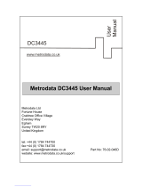
Back and Front Panels Figure 1 shows the back panel of the PathBuilder switch.
Figure 1 Back Panel
Figure 2 shows the front panel of the model S500 PathBuilder switch.
Figure 3 shows the front panel of the model S574 and model S578
PathBuilder switch.
Figure 4 shows the front panel of the model S580 PathBuilder switch.
Figure 5 shows the front panel of the model S590 PathBuilder switch.
Figure 6 shows the front panel of the model S593/S595 PathBuilder
switch.
Figure 7 shows the front panel of the model S598 PathBuilder switch.
Figure 8 shows the front panel of the model S599 PathBuilder switch.
Power
receptacle
On/off
switch
MODEL: xxxxxxx
xxxxxx
PATHBUILDER
xxx
S/N:
1SC05427
100-240VAC, 50/60HZ, 1.0-0.5A
250V, F2A
8.3
FOR CONTINUED PROTECTION
AGAINST FIRE HAZARD
REPLACE FUSE ONY WITH
SAME TYPE AND RATING
NTWK
ADDR:
3COM CORP.
SANTA CLARA, CA. MADE IN USA
080002 04BA1E LAN
04BA1F
04BA20
04BA21
WAN-A
WAN-B
WAN-C
20-0261-000
07/31/95
RPS
connector
Product
information label
/