Cisco UCS B200 M4 Installation And Service Note

Category
Servers
Type
Installation And Service Note

Cisco UCS B200 M4 is a density-optimized, half-width blade server that supports two CPU sockets for Intel E5-2600 v3 series CPUs and up to 24 DDR4 DIMMs. It supports one modular LOM (dedicated slot for Cisco's Virtual Interface Card) and one mezzanine adapter. Additionally, the UCS B200 M4 supports an optional storage module that supports up to 2 SAS or SATA hard drives or solid state disks (SSDs). You can install up to eight UCS B200 blade servers in a UCS chassis, mixing with other models or Cisco UCS blade servers in the chassis if desired.

Cisco UCS B200 M4 is a density-optimized, half-width blade server that supports two CPU sockets for Intel E5-2600 v3 series CPUs and up to 24 DDR4 DIMMs. It supports one modular LOM (dedicated slot for Cisco's Virtual Interface Card) and one mezzanine adapter. Additionally, the UCS B200 M4 supports an optional storage module that supports up to 2 SAS or SATA hard drives or solid state disks (SSDs). You can install up to eight UCS B200 blade servers in a UCS chassis, mixing with other models or Cisco UCS blade servers in the chassis if desired.

Cisco UCS B200 M4 Blade Server Installation and Service Note
Cisco UCS B200 M4 Blade Server 2
LEDs 2
Buttons 4
Connectors 4
Secure Digital (SD) Card Access 5
Storage Module 5
Removing a Blade Server Cover 6
Installing the Storage Module 7
Hard Drive Replacement 7
Blade Server Removal and Installation 9
Internal Components 12
Air Baffles 13
Diagnostics Button and LEDs 13
Working Inside the Blade Server 14
Installing and Enabling a Trusted Platform Module 26
Server Troubleshooting 28
Server Configuration 28
Physical Specifications for the Cisco UCS B200 M4 Blade Server 29
Obtaining Documentation and Submitting a Service Request 29
Revised: April 17, 2015,
Cisco UCS B200 M4 Blade Server
The Cisco UCS B200 M4 is a density-optimized, half-width blade server that supports two CPU sockets for Intel E5-2600 v3 series
CPUs and up to 24 DDR4 DIMMs. It supports one modular LOM (dedicated slot for Cisco's Virtual Interface Card) and one mezzanine
adapter. In addition, the UCS B200 M4 supports an optional storage module that supports up to 2 SAS or SATA hard drives or solid
state disks (SSDs) . You can install up to eight UCS B200 blade servers in a UCS chassis, mixing with other models or Cisco UCS
blade servers in the chassis if desired.
The UCS B200 M3 blade server is still available and is documented in separately.
Figure 1: Cisco UCS B200 M4 Front Panel
Blade ejector handle2Asset pull tag
Each server has a blank plastic tag that pulls out
of the front panel which is provided so that you
can add your own asset tracking label without
interfering with the intended air flow.
1
Hard drive bay 14Ejector captive screw3
Power button and LED6Hard drive bay 25
Blade health LED8Network link status LED7
Reset button access10Local console connector9
Locator button and LED11
LEDs
Server LEDs indicate whether the blade server is in active or standby mode, the status of the network link, the overall health of the
blade server, and whether the server is set to give a flashing blue beaconing indication.
The removable drives also have LEDs indicating hard disk access activity and disk health.
2
Table 1: Blade Server LEDs
DescriptionColorLED
Power off.OffPower
Main power state. Power is supplied to all server components in
normal operation.
Green
Standby power state. Power is supplied only to the service processor
(BMC) of the server so that the server can still be managed.
If you press and release the front-panel power button, the
server performs an orderly shutdown of the 12 V main
power and goes to standby power state. You cannot shut
down standby power from the front-panel power button.
See the Cisco UCS Manager Configuration Guide for your
release for information about completely powering off the
server from the software interface.
Note
Amber
None of the network links are up.OffLink
At least one network link is up.Green
Power off.OffHealth
Normal operation.Green
Minor error.Amber
Critical error.Blinking Amber
Beaconing not enabled.OffBeaconing
Beaconing to locate a selected bladeIf the LED is not blinking,
the blade is not selected. You can initiate beaconing in UCS Manager
or by using the Locator button.
Blinking blue 1 Hz
Inactive.OffActivity
(Disk Drive)
Outstanding I/O to disk drive.Green
Rebuild in progress. Health LED will flash in unison.Flashing Green
4 Hz
Identify drive active.Flashing Green
4 hz
3
DescriptionColorLED
Can mean either no fault detected or the drive is not installed.OffHealth
(Disk Drive)
Rebuild drive active. If the Activity LED is also flashing green, a
drive rebuild is in progress.
Flashing Amber
4 hz
Fault detected.Amber
Buttons
The Reset button is just inside the chassis and must be pressed using the tip of a paper clip or a similar item. Hold the button down
for five seconds, and then release it to restart the server if other methods of restarting are not working.
The beaconing function for an individual server may get turned on or off by pressing the combination button and LED.
The power button and LED allows you to manually take a server temporarily out of service but leave it in a state where it can be
restarted quickly. If the desired power state for a service profile associated with a blade server or an integrated rack-mount server is
set to "off", using the power button or Cisco UCS Manager to reset the server will cause the desired power state of the server to
become out of sync with the actual power state and the server may unexpected shutdown at a later time. To safely reboot a server
from a power-down state, use the Boot Server action in Cisco UCS Manager.
Connectors
The console port allows a direct connection to a blade server to allow operating system installation and other management tasks to
be done directly rather than remotely. The port uses the KVM dongle cable (N20-BKVM) which provides a connection into a Cisco
UCS blade server; it has a DB9 serial connector, a VGA connector for a monitor, and dual USB ports for a keyboard and mouse.
With this cable, you can create a direct connection to the operating system and the BIOS running on a blade server. A KVM cable
ships standard with each blade chassis accessory kit.
Figure 2: KVM Cable for Blade Servers
VGA connection for a monitor3Connector to blade server slot1
2-port USB connector for a mouse and keyboard4DB9 serial connector2
4
Secure Digital (SD) Card Access
SD card slots are provided and one or two SD cards can be populated. If two SD cards are populated, they can be used in a mirrored
mode (Cisco UCS Manager 2.2.x and later required).
Do not mix 16 GB and 32 GB SD cards in the same server.Note
The SD cards UCS-SD-32G-S and UCS-SD-64G-S can be used to store operating system boot images or other information. Once
the server has been removed from the chassis, you can access the SD card slots by rotating the latch up so that it does not cover the
slots. Remove or insert the SD cards as needed. Either or both slots may be used. Rotate the latch down to cover the slots before
installing the server in the chassis.
Figure 3: SD Card Slot Locations
Storage Module
The Cisco UCS B200 M4 blade server has an optional storage module that can be configured with SAS or SATA hard drives or solid
state disks (SSDs). Because the UCS B200 M4 can be used without disk drives, it does not necessarily come with the storage module
installed. A pair of blanking panels (two with this product ID: UCSB-LSTOR-BK) may be in place on a new UCS B200 M4 blade
server.
For information on installing the storage module, see Installing the Storage Module, on page 7.
5
Removing a Blade Server Cover
Replacing the cover is the reverse of removing the cover.
Procedure
Step 1
Press and hold the button down as shown in the figure below.
Step 2
While holding the back end of the cover, pull the cover back and then up.
Figure 4: Opening a Cisco UCS B200 M4 Blade Server
6
Installing the Storage Module
Procedure
Step 1
Place the storage module over the two standoff posts on the motherboard at the front of the server.
Step 2
Press down on the drive bay cage where it is labeled "Press Here to Install" until the storage module clicks into place.
Figure 5: Storage Module
Step 3
Using a Phillips-head screwdriver, tighten the four screws to secure the storage module. The locations of the screws are
labeled "Secure Here."
Hard Drive Replacement
The RAID storage module has two front-accessible drive bays that support hot-swappable, 2.5 inch drives. If you purchased the UCS
B200 M4 blade server without the storage module configured as a part of the system, a pair of blanking panels (UCSB-LSTOR-BK)
may be in place. These panels should be removed before installing a hard drive, but should remain in place to ensure proper cooling
and ventilation if the drive bay is unused .
You can remove and install blade server hard drives without removing the blade server from the chassis.
The drives supported in this blade server come with the drive sled attached. Spare drive sleds are not available. A list of currently
supported drives is in the specification sheets at: http://www.cisco.com/en/US/products/ps10280/products_data_sheets_list.html
7
Before upgrading or adding an HDD to a running system, check the service profile in Cisco UCS Manager and make sure the new
hardware configuration will be within the parameters allowed by the service profile.
To prevent ESD damage, wear grounding wrist straps during these procedures and handle modules by the
carrier edges only.
Caution
RAID Considerations
If the drive being replaced was part of a RAID array, Cisco recommends using a new drive of identical size, model, and manufacturer
to replace the failed drive. This recommendation comes from the industry standard practice of using drives of the same capacity when
creating RAID volumes. If drives of different capacities are used, the useable portion of the smallest drive will be used on all drives
that make up the RAID volume.
If you need to move a RAID volume from one server to another, both the old and new servers for the cluster must use the same LSI
controller. For example, migrating from a server with an LSI SAS1064E controller (B200 M2) to a server with a LSI SAS2008
MegaRAID controller (B200 M3) is not supported. Similarly, migrating a RAID controller volume from a UCS B200 M4 to a UCS
B420 M3 is not supported. However, migrating the RAID volume with LSI controllers is supported if you are migrating from a UCS
B200 M3 to a UCS B200 M4 blade server and running one of the following operating systems: RHEL 6.5, RHEL 7.0, Windows
Server 2012, and Windows Server 2012 R2.
For hard disk and RAID troubleshooting information, see the Cisco UCS Manager B-Series Troubleshooting Guide.
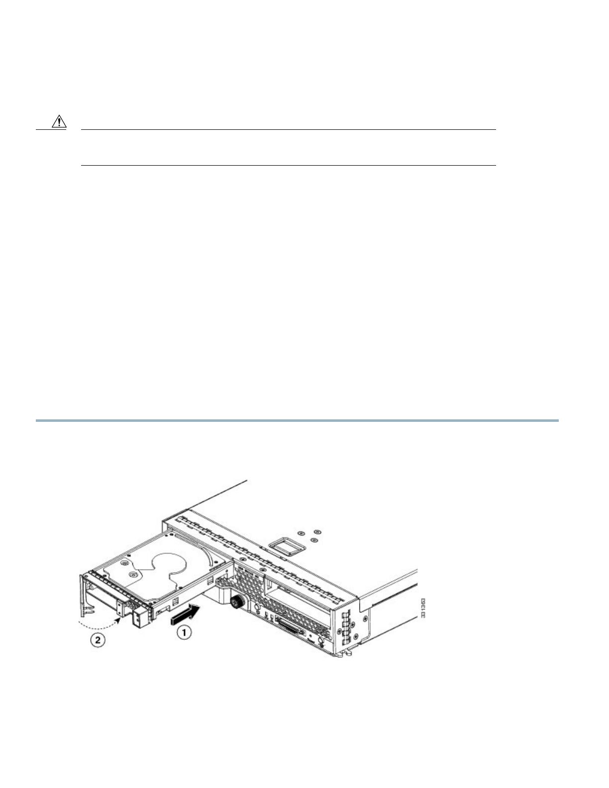
Installing a Blade Server Hard Drive
Procedure
Step 1
Place the hard drive lever into the open position by pushing the release button.
Figure 6: Installing a Hard Drive in a Blade Server
Step 2
Gently slide the hard drive into the opening in the blade server until it seats into place.
Step 3
Push the hard drive lever into the closed position.
8
You can use Cisco UCS Manager to format and configure RAID services. For details, see the Configuration Guide for the
version of Cisco UCS Manager that you are using. The configuration guides are available at the following URL: http://
www.cisco.com/en/US/products/ps10281/products_installation_and_configuration_guides_list.html
If you need to move a RAID cluster, see the Cisco UCS Manager B-Series Troubleshooting Guide.
Removing a Blade Server Hard Drive
To remove a hard drive from a blade server, follow these steps:
Procedure
Step 1
Push the button to release the ejector, and then pull the hard drive from its slot.
Step 2
Place the hard drive on an antistatic mat or antistatic foam if you are not immediately reinstalling it in another server.
Step 3
Install a hard disk drive blank faceplate to keep dust out of the blade server if the slot will remain empty.
Blade Server Removal and Installation
Before performing any internal operations on this blade server, you must remove it from the chassis.
To prevent ESD damage, wear grounding wrist straps during these procedures and handle modules by the
carrier edges only.
Caution
Powering Off Blade Servers Using the Power Button
You can also shut the server down remotely using Cisco UCS Manager. For details, see the Configuration
Guide for the version of Cisco UCS Manager that you are using. The configuration guides are available
at the following URL: http://www.cisco.com/en/US/products/ps10281/products_installation_and_
configuration_guides_list.html
Tip
Procedure
Step 1
For each server in the chassis that you want to power off, check the color of the Power Status LED.
Green indicates that the server is running and must be shut down before it can be safely powered off. Go to Step 2.
Amber indicates that the server is already in standby mode and can be safely powered off. Go to Step 3.
Step 2
Press and release the Power button, then wait until the Power Status LED changes to amber.
9
The operating system performs a graceful shutdown and the server goes to standby mode.
To avoid data loss or damage to your operating system, you should always invoke a graceful shutdown of the
operating system.
Caution
Step 3
(Optional) If you are shutting down all blade servers in a chassis, disconnect the power cords from the chassis to completely
power off the servers.
Step 4
Remove the appropriate servers from the chassis.
Removing a Blade Server
Using UCS Manager, decommission the server before physically removing the server. To remove a blade server from the chassis,
follow these steps:
Procedure
Step 1
Loosen the captive screw on the front of the blade.
Step 2
Remove the blade from the chassis by pulling the ejector lever on the blade until it unseats the blade server.
Step 3
Slide the blade part of the way out of the chassis, and place your other hand under the blade to support its weight.
Step 4
Once removed, place the blade on an antistatic mat or antistatic foam if you are not immediately reinstalling it into another
slot.
Step 5
If the slot is to remain empty, install a blank faceplate (N20-CBLKB1) to keep dust out of the chassis.
Installing a Half-width Blade Server
UCS B200 M4, UCS B200 M3, and UCS B22 M3 half-width blade servers are interoperable in a UCS chassis with any other UCS
blade servers, including prior generation B200 M2 and B200 M1 servers, or other UCS B-Series blade servers. To install a half-width
blade server, follow these steps:
10
Procedure
Step 1
Grasp the front of the blade server and place your other hand under the blade to support it.
Figure 7: Positioning a Blade Server in the Chassis
Step 2
Open the ejector lever in the front of the blade server.
Step 3
Gently slide the blade into the opening until you cannot push it any farther.
Step 4
Press the ejector lever so that it catches the edge of the chassis and presses the blade server all the way in.
Step 5
Tighten the captive screw on the front of the blade to no more than 3 in-lbs. Tightening with bare fingers only is unlikely
to lead to stripped or damaged captive screws.
Step 6
Power on the server. UCS Manager automatically reacknowledges, reassociates, and recommissions the server, provided
any hardware changes are allowed by the service profile.
11
Internal Components
Figure 8: Inside View of the UCS B200 M4 Blade Server
Modular storage subsystem connector2SD card slots1
DIMM slots4USB connector
An internal USB 2.0 port is supported. A 16
GB USB drive (UCS-USBFLSHB-16GB)
is available from Cisco. A clearance of 0.950
inches (24.1 mm) is required for the USB
device to be inserted and removed.
3
CPU heat sink install guide pins6Front heat sink and CPU 15
CMOS battery8Rear heat sink and CPU 27
DIMM diagnostic LED button10Trusted Platform Module (TPM)9
Adapter slot 212Adapter slot 111
When the storage module is installed, the USB connector is underneath it. Use the small cutout opening
in the storage module to visually determine the location of the USB connector when you need to insert it.
Note
12
Air Baffles
The air baffles direct and improve air flow for the server components. Two identical baffles ship with each B200 M4 server. No tools
are necessary to install them, just place them over the DIMMs as shown, with the holes in the center of the baffles aligned with the
corresponding motherboard standoffs.
Figure 9: Cisco UCS B200 M3 Air Baffles
Diagnostics Button and LEDs
At blade start-up, POST diagnostics test the CPUs, DIMMs, HDDs, and adapter cards, and any failure notifications are sent to UCS
Manager. You can view these notifications in the System Error Log or in the output of the show tech-support command. If errors
are found, an amber diagnostic LED also lights up next to the failed component. During run time, the blade BIOS, component drivers,
and OS all monitor for hardware faults and will light up the amber diagnostic LED for a component if an uncorrectable error or
correctable errors (such as a host ECC error) over the allowed threshold occur.
LED states are saved, and if you remove the blade from the chassis the LED values will persist for up to 10 minutes. Pressing the
LED diagnostics button on the motherboard causes the LEDs that currently show a component fault to light for up to 30 seconds for
easier component identification. LED fault values are reset when the blade is reinserted into the chassis and booted, and the process
begins from its start.
If DIMM insertion errors are detected, they may cause the blade discovery to fail and errors will be reported in the server POST
information, which is viewable using the UCS Manager GUI or CLI. UCS blade servers require specific rules to be followed when
populating DIMMs in a blade server, and the rules depend on the blade server model. Refer to the documentation for a specific blade
server for those rules.
13
HDD status LEDs are on the front face of the HDD. Faults on the CPU, DIMMs, or adapter cards also cause the server health LED
to light solid amber for minor error conditions or blinking amber for critical error conditions.
Working Inside the Blade Server
Installing a Motherboard CMOS Battery
All Cisco UCS blade servers use a CR2032 battery (Cisco PID N20-MBLIBATT=) to preserve BIOS settings while the server is
powered down.
There is danger of explosion if the battery is replaced incorrectly. Replace the battery only with the same
or equivalent type recommended by the manufacturer. Dispose of used batteries according to the
manufacturers instructions.
Warning
To install or replace a motherboard complementary metal-oxide semiconductor (CMOS) battery, follow these steps:
Procedure
Step 1
Remove the old CMOS battery:
a) Power off the blade, remove it from the chassis, and remove the top cover.
b) Push the battery socket retaining clip away from the battery.
c) Lift the battery from the socket. Use needle-nose pliers to grasp the battery if there is not enough clearance for your
fingers.
Step 2
Install a motherboard CMOS battery:
a) Push the battery socket retaining clip away from where the battery fits in the housing.
b)
Insert the new battery into the socket with the batterys positive (+) marking facing away from the retaining clip. Ensure
that the retaining clip can click over the top of the battery to secure it in the housing.
c) Replace the top cover.
14
d) Replace the server in the chassis and power on the blade by pressing the Power button.
Figure 10: Location of the Motherboard CMOS Battery
15
CPU and Heatsink Replacement
Removing a Heat Sink and CPU
Procedure
Step 1
Unscrew the four captive screws.
Step 2
Remove the heat sink.
Figure 11: Removing the Heat Sink and CPU
16
Step 3
Unhook the self-loading socket (SLS) lever .
Step 4
Unhook the SLS lever .
Step 5
Grasp the sides of the CPU carrier (indicated by the arrows in the illustration) and swing it into a standing position in the
SLS plug seat.
Figure 12: CPU Carrier and SLS Plug Seat
Step 6
Pull the CPU carrier up and out of the SLS plug seat.
Installing a New CPU and Heat Sink
Before installing a new CPU in a server, verify the following:
The CPU is supported for that given server model. This may be verified through the server Technical Specifications ordering
guides or by the relevant release of the Cisco UCS Capability Catalog.
A BIOS update is available and installed that supports the CPU and the given server configuration.
If the server will be managed by Cisco UCS Manager, the service profile for this server in Cisco UCS Manager will recognize
and allow the new CPU.
The CPUs and heat sinks are different and must be installed in the correct location. The front heat sink and CPU 1 can only be
installed in the front of the blade server and the rear heat sink and CPU 2 can only be installed in the rear of the blade server.
17
Procedure
Step 1
Hold the CPU carrier by its sides (indicated b the arrows). Insert and align the two CPU carrier pegs into the self-loading
socket (SLS) plug seat. To ensure proper seating, verify that the horizontal yellow line below the word ALIGN is straight.
Figure 13: Inserting the CPU Carrier
18
Step 2
Press gently on the top of the CPU carrier from the exterior side until it snaps into place.
Step 3
Close the socket latch.
Step 4
Hook the self-loading socket (SLS) lever .
Step 5
Hook the SLS lever .
Step 6
Thermally bond the CPU and heat sink using the thermal grease provided.
Step 7
Replace the heat sink. The yellow CPU heat sink install guide pins that are attached to the motherboard must align with
the cutout on the heat sink to ensure proper installation of the heat sink.
Figure 14: Replacing the Heat Sink
Step 8
Tighten the four captive screws in the order shown.
Memory and Performance
Installing Memory
To install a DIMM into the blade server, follow these steps:
Procedure
Step 1
Open both DIMM connector latches.
19
Step 2
Press the DIMM into its slot evenly on both ends until it clicks into place.
DIMMs are keyed. If a gentle force is not sufficient, make sure the notch on the DIMM is correctly aligned.
Be sure that the notch in the DIMM aligns with the slot. If the notch is misaligned you may damage the DIMM,
the slot, or both.
Note
Step 3
Press the DIMM connector latches inward slightly to seat them fully.
Supported DIMMs
The DIMMs supported in this blade server are constantly being updated. A list of currently supported and available DIMMs is in the
specification sheets at:
http://www.cisco.com/en/US/products/ps10280/products_data_sheets_list.html
Do not use any memory DIMMs other than those listed in the specification sheet. Doing so may irreparably damage the server and
require an RMA and down time.
Memory Arrangement
The blade server contains 24 DIMM slots12 for each CPU. Each set of 12 DIMM slots is arranged into four channels, where each
channel has three DIMMs.
Figure 15: Memory Slots In the Blade Server
Channels E-H for CPU 22Channels A-D for CPU 11
DIMMs and Channels
Each channel is identified by a letterA, B, C, D for CPU1, and E, F, G, H for CPU 2. Each DIMM slot is numbered 1, 2, or 3. Note
that each DIMM slot 1 is blue, each slot 2 is black, and each slot 3 is off-white or beige.
20
1 / 1

Cisco UCS B200 M4 Installation And Service Note

Category
Servers
Type
Installation And Service Note

Cisco UCS B200 M4 is a density-optimized, half-width blade server that supports two CPU sockets for Intel E5-2600 v3 series CPUs and up to 24 DDR4 DIMMs. It supports one modular LOM (dedicated slot for Cisco's Virtual Interface Card) and one mezzanine adapter. Additionally, the UCS B200 M4 supports an optional storage module that supports up to 2 SAS or SATA hard drives or solid state disks (SSDs). You can install up to eight UCS B200 blade servers in a UCS chassis, mixing with other models or Cisco UCS blade servers in the chassis if desired.

Ask a question and I''ll find the answer in the document

Finding information in a document is now easier with AI

Ask the document