Page is loading ...

HYDRO SS 700
OPERATOR’S MANUAL
Read & Understand
Retain for Future Reference
NOTICE
►
BENCH TOP
►
HANGING SUMP

Read operator’s manual carefully and thoroughly.
Understand all safety warnings and instructions before
attempting operation of the unit.
DO NOT OPERATE THE UNIT DRY (FULL WATER SUPPLY
REQUIRED IN THE SUMP). This would cause permanent
damage to the unit’s sump pump.
Hydro 700 must be properly grounded as a precaution against possible
electric shock. Always check for the correct voltage.
Always disconnect power before inspecting or servicing machine.
Keep cord away from heat, oil, sharp edges and moving parts. Replace
damaged cords immediately. Damaged cords increase the risk of electric
shock.
If use of an extension cord is necessary, use a heavy, gauge 3 wire extension
cord with a molded three-prong plug (See installation).
Keep hands and all objects from entering the path of the blade.
Install the Hydro SS 700 at bench-top height or higher for added safety and
optimum performance.
Do not use ammable liquids, caustic materials, or corrosive materials with
the Hydro SS 700.
When servicing Hydro SS 700, use only identical replacement parts
and follow instructions in the maintenance section of this manual. Use
of unauthorized parts or failure to follow maintenance instructions may
damage equipment or cause personal injury.
1 - Bench Top or Hanging Sump unit
1 - Operator’s Manual
5 - Wire Ties
1 - Hanger Bolt Assy. (Hanging Sump only)
When unpacking your unit,
Locate the following items.
THE HYDRO SS 700 CAN BE AUTOMATED WHEN USED
IN CONJUNCTION WITH A CONTROL. A FAN MAY NOT
APPEAR POWERED BUT COULD SUDDENLY BEGIN HIGH-SPEED ROATATION AS A
FUNCTION OF THE PRESET CONTROL.
CAUTION
GROUND FAULT RECAPTACLES ARE STRONGLY
RECOMMENDED AND MAY BE REQUIRED BY LAW.
NOTICE
GENERAL SAFETY
UNPACKING
1.
2.
3.
4.
5.
6.
7.
8.
9.
10.

Layout Guidelines
Small structures
In applications requiring only one unit,
install the unit anywhere along one end
wall, propelling the fog up and horizontally
down the length of the structure. If there
is forced ventilation, choose the intake
end of the structure. The best location for
automated controls is behind the fan at an
easily-accessible level for monitoring.
Large structures
Equally space the units within the
structure. Lower humidity and/or
cooling requirements can allow for
greater distance between fans. Usually,
the maximum distance between fans
should be 20’ from the side and 35’
from the front. If the structure has
forced ventilation, shift the fans closer
to the intake end. The fans should
always be propelling their fog with the
direction of natural or forced air ow.
Control location area
Placement Guidelines
Mount the fan high overhead in the largest available open area.
As a general rule, the higher the better when mounting your fan.
Allow one foot above the unit and adequate room in front of and
below the fan for the unobstructed propulsion of the fog.
Mount the fan near the intake end of a ventilated structure. In
structures with no ventilation, install the unit at the largest, most
open end and propel the fog toward the opposite end.
Utilize the pivoting fogging head in order to maximize the unit’s performance.
DO NOT Propel the fog into the wind (direction of airow).
DO NOT Pivot the fogging head to propel fog at a sharp downward angle.
DO NOT Cramp the fan in tight spaces or skinny aisleways.
DO NOT Mount the fan near the ground or underneath tables or benches. This
would result in a high loss of fog onto the ground, though it would not
cause mechanical harm to the unit.
PLACEMENT & LAYOUT
10’
35’
20’
Direction of air ow →
Direction of air ow →

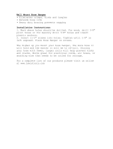
Installation
Find a Suitable Location:
For Bench Tops, nd a stable, at surface.
For Hanging Sumps, locate a support capable of handling over 25
pounds. Drill a 5/16” clearance hole through the support where
you want to hang the unit. Using 1/2” wrenches, secure the unit
into position with hardware provided. See Fig. 1
Insert Drainage Line: Place the drainage line into the sump box.
See Fig. 3A
Connect Water Supply: Hydro SS units come equipped with a
standard garden hose connector and 1/4” water line tubing. Simply connect to an
available hose bib.
To remove hose connector, apply pressure to the retaining clip while pulling on the
tubing. See Fig. 2
Connect Power Supply: Plug directly into a properly grounded receptacle. If equipped
with a Humidistat, Thermostat, or Cycle Timer Control, plug the control into a receptacle
and then plug the fan into the female side of the control’s pre-wired plug. See Fig. 3
Operation
Adjusting fog output: After the unit has been
plugged in and the water turned on, you can
adjust fogging output with the quarter turn ow
control valve located at the back of the unit next
to the switch box. The valve is fully open when
the lever is down, pointing straight back, and
fully closed when the lever is pointing straight
up. You may also adjust it anywhere in between.
Pivot Feature: Pivot the fogging head anywhere
between 15° down and 40° up from neutral.
The manufacturer’s recommended angle is
about 30° up.
Pull on tubing
Hose Connector
Push on retaining ring
Flow
Control
Valve
Switch
Box
Fogging
Head
Fig. 3A
Drain
Line
Return
INSTALLATION & OPERATION
Fig. 2
Fig. 3
or
With DF Control
No Control
115V
Receptacle
DF Control
“Piggyback”
Pre-wired Plug
Fig. 1

Impeller
Pump
Cover
Tube Fitting
Shaft
Lubricate Motor: Remove two blue plugs at the top of the
motor. Apply 4-5 drops of light grade petroleum based oil
at each bearing location 1 to 2 times a year or as needed.
Replace blue plugs. See Fig. 4
Clean Pump and Sump: Periodically clean debris from inside
the sump area and nearby the pump. If you need to clean
inside the pump, the cover easily snaps off. See Fig. 5
Clean Blade Assembly: After carefully
removing the blade assembly, remove the
stainless steel cover and O-ring. Soak the
blades in CLR for one hour, scrub clean
and rinse off with water. Carefully check the
small holes leading into passageways that
extend the length of each blade.
See Fig.6
When thoroughly clean, test by blowing a
small amount of air through each blade.
Winterizing: Protect your unit from winter damage.
If storing unit in freezing temperatures, be sure all
uid is drained from the unit.
MAINTENANCE
Fig. 5
Blade Resivor
Water Passageway
O-ring
Stainless Face Plate
Blade
Assy.
Fig. 6
NO FOG
1. Clogged Pump Filter
2. Badly Worn Pump Impeller
3. Clogged or Dead Pump
4. Not Getting Enough Water
5. Low Water Pressure Supply
6. Clogged SST Feed Tube
SPORADIC FOG
1. Worn/ Loose Pump Impeller
2. Not Getting Enough Water
POOR QUALITY FOG
1. Clogged Blade Assembly
2. Clogged Pump Filter
3. Stiff/Locked Motor Shaft
FAN DOES NOT SPIN
1. Stiff/Locked Motor Shaft
2. Bad Motor
3. Bad Electrical Connections
MOTOR OVERHEATING
1. Stiff/Locked Motor Shaft
2. Bad Motor
OVER FLOWING
1. Leaking Float Valve Assy.
1. Clean Sump Area. Remove pump lter, wash with soapy water and reinstall.
2. Make sure sump is getting ample water. Replace with new pump or impeller.
3. Remove, disassemble, clean and electrically test before reinstalling.
4. Check, clean or replace oat valve assembly. Check water supply lline for kinks.
5. A booster pump may be necessary with some low pressure RO supplies.
6. Remove, ream out with a small wire, clean and reinstall.
1. Replace with a new pump impeller or new pump.
2. Check oat valve assembly. Check water supply for kinks or low water pressure.
1. Remove assembly and clean out the rear reservoir and the blades’ passageways.
2. Clean sump area. Remove pump lter, wash with soapy water and reinstall.
3. Lubricate motor bearings while manually rotating shaft back and forth until loose.
1. Lubricate motor bearings while manually rotating shaft back and forth until loose.
2. If motor smells, doesn’t start or shaft will not loosen-up, replace motor.
3. Check for loose connections. Test motor and controls with a direct power supply.
1. Lubricate motor bearings while manually rotating shaft back and forth until loose.
2. If motor smells, doesn’t start or shaft will not loosen-up, replace motor.
1. Check for a bad seal or debris in oat valve assembly. Replace if necessary.
Troubleshooting
Possible Cause(s) Corrective Action
3 in 1
oil
Oil ports
Fig. 4

Fan Blade Assembly
First remove the atomizing ring/front
guard assembly. The blade assembly
is press-tted onto the motor shaft.
Position ngers behind both sides of the
hub with forearms pressed up against
the rim of the housing. Use the housing’s
rim as leverage and pull the blade
assembly outward towards the front. See
Fig. 8 Pull primarily on the hub portion of
the blade assembly; excess force on the
blades can cause damage. To reinstall,
press on using the palm of one hand
while the other hand is supporting the
unit.
Motor
Disconnect the electrical power. After
removing the atomizing ring/front guard
assembly, and the blade assembly, use
a 3/8” nut driver or wrench to remove
the four 10-24 nuts behind the blade
assembly securing the motor to the rear
guard. See Fig. 8
Pump
Disconnect the electrical power. With a
Phillips screwdriver, remove the sump
cover screws and the pump support screws. See Fig. 9 Disconnect the plumbing on
top of the pump and un-wire the pump’s electrical cord that leads inside the ON/OFF
Switch Box. Reinstall in the reverse order. Note: Only nger tighten the brass tube
tting when threading it into the top of the pump.
Fig. 8
Fig. 7
10-24 Flange Nuts
10-24
Nuts
Motor
Atomizing Ring/Front
Guard Assy.
Pump Support
Screws
Sump
Sump
Cover
Sump Cover
Screws
Float Valve
Assembly’s
Location
Pump’s
Location
Fig. 9
SERVICE & REPAIR
Atomizing Ring/Front Guard
Assembly
Using a 3/8” nut driver or wrench,
remove four 10-24 ange nuts
located at the back of the housing.
See Fig. 7. Remove the guard/
atomizing assembly out the front
fan opening. To reinstall, it is
easiest to work the bottom legs
into position and nger tighten
their nuts rst before working the
upper two legs into position.
↔

3
6
7
1
2
5
9
10
13
14
15
16
12
4
8
11
17
18
19
20
21
22
23
24
DESCRIPTION PART NO.
1 Atomizing Ring 400-001
2 Front Guard 400-002
3 Motor 1/20hp 115V 400-110
4 Rear Guard 400-127
5 Blade Assembly 400-128
6 Housing 400-100
7 Hanger Assembly 400-129
8 SST Water Feed Tube 400-130
9 Pivot Location NA
10 Sump 400-131
11 Float Valve Assembly 400-132
12 Flow Control Valve 400-016
13 Support Assembly 400-133
14 Pump 400-134
15 Pump Bracket 400-135
16 Pump Filter 400-137
17 115V Power Switch 109
18 Switch Box 82
19 Switch Box Cover 85
20 Power Cord 400-023
21 Drain Barb Fitting 400-114
22 Drain Hose 400-089
23 1/4” Water Tubing W-14
24 Garden Hose Connect W-2
REPLACEMENT PART IDENTIFICATION
HANGING SUMP
MODEL
BENCH TOP
MODEL

Aquafog and accessories are warranted to the original purchaser
against defects in material and workmanship under normal use for one full
year from date of purchase. Any part determined to be defective and returned
to the manufacturer, shipping cost prepaid, will be repaired or replaced at
Jaybird Manufacturing, Inc.'s discretion without charge. Proof of purchase
date and an explanation of the problem or complaint must accompany the
returned portion of the machine.
Jaybird Manufacturing, Inc. reserves the right to verify the legitimacy
of claimed defects. The provisions of this warranty do not apply to damage
resulting from direct or indirect misuse, negligence, accident, lack of main-
tenance, or unauthorized repairs or alterations which affect the machine's
performance or reliability.
LIMITATIONS OF LIABILITY. TO THE EXTENT ALLOWABLE UNDER
APPLICABLE LAW, JAYBIRD MANUFACTURING, INC.'S LIABILITY FOR DEATH,
INJURIES TO PERSONS OR PROPERTY, OR FOR CONSEQUENTIAL OR INCI-
DENTAL DAMAGES ARISING FROM THE USE OF OUR EQUIPMENT IS
EXPRESSLY DISCLAIMED. JAYBIRD MANUFACTURING, INC.'S LIABILITY IN
ALL EVENTS IS LIMITED TO, AND SHALL NOT EXCEED, THE PURCHASE PRICE
PAID. NO OTHER WARRANTY, EXPRESSED OR IMPLIED, IS AUTHORIZED,
INCLUDING WARRANTIES OF MERCHANTABILITY AND FITNESS FOR A PAR-
TICULAR PURPOSE.
This warranty gives you specic legal rights, and you may also have other rights,
which vary from state to state.
1
year
ONE YEAR LIMITED WARRANTY
Printed in U.S.A.
© 2015 Jaybird Mfg., Inc.
Jaybird Manufacturing, Inc.
135 Summer Lane
Centre Hall, PA 16828
Parts & Service: 1.814.364.1800
Website: www.jaybird-mfg.com
/