Page is loading ...

Instruction Manual
748468-E
August 2003
http://www.raihome.com
Model MicroCEM SHS
Sample Handling System
IB-103-102

Emerson Process Management
Rosemount Analytical Inc.
Process Analytic Division
6565P Davis Industrial Parkway
Solon, OH 44139
T (440) 914-1261
F (440) 914-1271
e-mail: gas.csc@EmersonProcess.com
http://www.raihome.com
ESSENTIAL INSTRUCTIONS
READ THIS PAGE BEFORE PROCEEDING!
Rosemount Analytical designs, manufactures and tests its products to meet many national and in-
ternational standards. Because these instruments are sophisticated technical products, you
MUST properly install, use, and maintain them
to ensure they continue to operate within their
normal specifications. The following instructions MUST be adhered to and integrated into your
safety program when installing, using, and maintaining Rosemount Analytical products. Failure to
follow the proper instructions may cause any one of the following situations to occur: Loss of life;
personal injury; property damage; damage to this instrument; and warranty invalidation.
• Read all instructions
prior to installing, operating, and servicing the product.
• If you do not understand any of the instructions, contact your Rosemount Analytical repre-
sentative for clarification.
• Follow all warnings, cautions, and instructions marked on and supplied with the product.
• Inform and educate your personnel in the proper installation, operation, and maintenance of the
product.
• Install your equipment as specified in the Installation Instructions of the appropriate Instruction
Manual and per applicable local and national codes. Connect all products to the proper electri-
cal and pressure sources.
• To ensure proper performance, use qualified personnel
to install, operate, update, program,
and maintain the product.
• When replacement parts are required, ensure that qualified people use replacement parts speci-
fied by Rosemount. Unauthorized parts and procedures can affect the product’s performance,
place the safe operation of your process at risk, and VOID YOUR WARRANTY
. Look-alike
substitutions may result in fire, electrical hazards, or improper operation.
• Ensure that all equipment doors are closed and protective covers are in place, except
when maintenance is being performed by qualified persons, to prevent electrical shock
and personal injury.
The information contained in this document is subject to change without notice.
Logos, trademarks and copyrights are property of their respective owners.

Instruction Manual
748468-E
August 2003
Rosemount Analytical Inc. A Division of Emerson Process Management Contents i
Model MicroCEM SHS
TABLE OF CONTENTS
PREFACE...........................................................................................................................................P-1
Definitions...........................................................................................................................................P-1
Intended Use Statement.....................................................................................................................P-2
Safety Summary.................................................................................................................................P-2
General Precautions For Handling And Storing High Pressure Gas Cylinders .................................P-4
Documentation....................................................................................................................................P-5
Compliances.......................................................................................................................................P-5
1-0 DESCRIPTION AND SPECIFICATIONS..............................................................................1-1
1-1 Overview................................................................................................................................1-1
1-2 MicroCEM SHS Specifications..............................................................................................1-2
2-0 INSTALLATION ....................................................................................................................2-1
2-1 Installation..............................................................................................................................2-1
3-0 OPERATION .........................................................................................................................3-1
3-1 Simplified Startup And Operation Procedure ........................................................................3-1
3-2 Calibration..............................................................................................................................3-2
3-3 Routine Operation .................................................................................................................3-2
4-0 MAINTENANCE AND SERVICE ..........................................................................................4-1
4-1 Preventive Maintenance........................................................................................................4-1
4-2 Corrective Maintenance.........................................................................................................4-1
4-3 Maintenance Logs.................................................................................................................4-1
4-4 Maintenance Frequency........................................................................................................4-1
5-0 TROUBLESHOOTING..........................................................................................................5-1
6-0 REPLACEMENT PARTS......................................................................................................6-1
6-1 Internal Sample Panel...........................................................................................................6-1
6-2 Sample Probes......................................................................................................................6-1
6-3 Hi Temp Components............................................................................................................6-1
7-0 RETURN OF MATERIAL......................................................................................................7-1
7-1 Return Of Material.................................................................................................................7-1
7-2 Customer Service..................................................................................................................7-1
7-3 Training..................................................................................................................................7-1
IB-103-102

Instruction Manual
748468-E
August 2003
ii Contents Rosemount Analytical Inc. A Division of Emerson Process Management
Model MicroCEM SHS
LIST OF ILLUSTRATIONS
Figure 1-1. MicroCEM Sample Handling System........................................................................ 1-1
Figure 1-2. MicroCEM Continuous Emissions Monitor................................................................ 1-1
LIST OF TABLES
Table 3-1. Typical Component Settings ...................................................................................... 3-1
Table 4-1. Component Maintenance Schedule - Filters.............................................................. 4-2
Table 4-2. Component Maintenance Schedule - Valves............................................................. 4-3
Table 4-3. Component Maintenance Schedule – Indicators....................................................... 4-4
Table 4-4. Component Maintenance Schedule – Pressure Adjustment..................................... 4-4
Table 4-5. Component Maintenance Schedule – Dryers............................................................ 4-5
Table 4-6. Component Maintenance Schedule – Temperature Control...................................... 4-6
Table 4-7. Component Maintenance Schedule – Electrical........................................................ 4-7
DRAWINGS (Located In Rear of Manual)
662011 Sample Probe 5’
662012 Sample Probe 4’
662320 Wiring Diagram, MicroCEM SHS
662321 Flow Diagram, MicroCEM SHS
662349 Installation Drawing, MicroCEM SHS
662350 Installation Drawing, MicroCEM SHS Hi Temp
IB-103-102

Instruction Manual
748468-E
August 2003
Rosemount Analytical Inc. A Division of Emerson Process Management Preface P-1
Model MicroCEM SHS
PREFACE
The purpose of this manual is to provide information concerning the components, functions,
installation and maintenance of the MicroCEM SHS.
Some sections may describe equipment not used in your configuration. The user should become
thoroughly familiar with the operation of this module before operating it. Read this instruction
manual completely.
DEFINITIONS
The following definitions apply to DANGERS, WARNINGS, CAUTIONS and NOTES found throughout
this publication.
DANGER .
Highlights the presence of a hazard which will cause severe personal injury, death, or substantial
property damage if the warning is ignored.
WARNING .
Highlights an operation or maintenance procedure, practice, condition, statement, etc. If not
strictly observed, could result in injury, death, or long-term health hazards of personnel.
CAUTION.
Highlights an operation or maintenance procedure, practice, condition, statement, etc. If not
strictly observed, could result in damage to or destruction of equipment, or loss of effectiveness.
NOTE
Highlights an essential operating procedure,
condition or statement.
IB-103-102

Instruction Manual
748468-E
August 2003
P-2 Preface Rosemount Analytical Inc. A Division of Emerson Process Management
Model MicroCEM SHS
INTENDED USE STATEMENT
The MicroCEM Sample Handling System is intended for use as an industrial process measurement
device only. It is not intended for use in medical, diagnostic, or life support applications, and no
independent agency certifications or approvals are to be implied as covering such applications.
SAFETY SUMMARY
If this equipment is used in a manner not specified in these instructions, protective systems may be
impaired.
AUTHORIZED PERSONNEL
To avoid explosion, loss of life, personal injury and damage to this equipment and on-site property,
do not operate or service this instrument before reading and understanding this instruction manual
and receiving appropriate training. Save these instructions.
DANGER.
ELECTRICAL SHOCK HAZARD
Do not open while energized. Installation requires access to live parts which can cause death or
serious injury.
For safety and proper performance this instrument must be connected to a properly grounded
three-wire source of power.
DANGER.
POSSIBLE EXPLOSION HAZARD
Do not operate without covers secure. Ensure that all gas connections are made as labeled and are
leak free. Improper gas connections could result in explosion and death.
WARNING.
DEVICE HAZARDOUS AREA CERTIFICATION(S)
Any addition, substitution, or replacement of components installed on or in this device, must be
certified to meet the hazardous area classification that the device was certified to prior to any such
component addition, substitution, or replacement. In addition, the installation of such device or
devices must meet the requirements specified and defined by the hazardous area classification of
the unmodified device. Any modifications to the device not meeting these requirements, will void
the product certification(s).
IB-103-102

Instruction Manual
748468-E
August 2003
Rosemount Analytical Inc. A Division of Emerson Process Management Preface P-3
Model MicroCEM SHS
WARNING.
PARTS INTEGRITY AND UPGRADES
Tampering with or unauthorized substitution of components may adversely affect the safety of this
instrument. Use only factory approved components for repair.
Because of the danger of introducing additional hazards, do not perform any unauthorized modifi-
cation to this instrument.
Return the instrument to Rosemount Analytical Customer Service Center. See Section 7.
CAUTION.
PRESSURIZED GAS
This unit requires periodic calibration with a known standard gas. It also may utilizes a pressur-
ized carrier gas, such as helium, hydrogen, or nitrogen. See General Precautions for Handling and
Storing High Pressure Gas Cylinders, page P-4.
CAUTION.
HEAVY WEIGHT
Use two persons or a suitable lifting device to move or carry the instrument.
IB-103-102

Instruction Manual
748468-E
August 2003
P-4 Preface Rosemount Analytical Inc. A Division of Emerson Process Management
Model MicroCEM SHS
GENERAL PRECAUTIONS FOR HANDLING AND STORING HIGH
PRESSURE GAS CYLINDERS
Edited from selected paragraphs of the Compressed Gas Association's "Handbook of Compressed
Gases" published in 1981
Compressed Gas Association
1235 Jefferson Davis Highway
Arlington, Virginia 22202
Used by Permission
1. Never drop cylinders or permit them to strike each other violently.
2. Cylinders may be stored in the open, but in such cases, should be protected against extremes of
weather and, to prevent rusting, from the dampness of the ground. Cylinders should be stored in the
shade when located in areas where extreme temperatures are prevalent.
3. The valve protection cap should be left on each cylinder until it has been secured against a wall or
bench, or placed in a cylinder stand, and is ready to be used.
4. Avoid dragging, rolling, or sliding cylinders, even for a short distance; they should be moved by using a
suitable hand-truck.
5. Never tamper with safety devices in valves or cylinders.
6. Do not store full and empty cylinders together. Serious suckback can occur when an empty cylinder is
attached to a pressurized system.
7. No part of cylinder should be subjected to a temperature higher than 125
°
F (52
°
C). A flame should
never be permitted to come in contact with any part of a compressed gas cylinder.
8. Do not place cylinders where they may become part of an electric circuit. When electric arc welding,
precautions must be taken to prevent striking an arc against the cylinder.
IB-103-102

Instruction Manual
748468-E
August 2003
Rosemount Analytical Inc. A Division of Emerson Process Management Preface P-5
Model MicroCEM SHS
DOCUMENTATION
The following MicroCEM SHS instruction materials are available. Contact Customer Service Center or
the local representative to order (See Section 7).
748467 Instruction Manual, MicroCEM Continuous Emission Monitor
748468 Instruction Manual, MicroCEM Sample Handling System (this document)
COMPLIANCES
This product may carry approvals from several certifying agencies. The certification marks appear on the
product name-rating plate.
CSA (Pending)
IB-103-102

Instruction Manual
748468-E
August 2003
P-6 Preface Rosemount Analytical Inc. A Division of Emerson Process Management
Model MicroCEM SHS
IB-103-102

Instruction Manual
748468-E
August 2003
Rosemount Analytical Inc. A Division of Emerson Process Management Description and Specifications 1-1
Model MicroCEM SHS
SECTION 1
DESCRIPTION AND SPECIFICATIONS
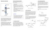
1-1 OVERVIEW
The MicroCEM Sample Handling System
(SHS) (Figure 1-1) is designed for use with
the MicroCEM Continuous Emission Monitor
(Figure 1-2) to continuously determine the
concentration of O
2
, CO, and NOx in a flow-
ing gaseous mixture.
The sampled gas is collected from the stack
and prepared by the Probe/Sample Handling
System for analysis and processing by the
Analysis Enclosure.
The MicroCEM SHS is enclosed in a rugged
NEMA 4X, IP65 type enclosure, for harsh en-
vironment.
Figure 1-1. MicroCEM Sample Handling System
Figure 1-2. MicroCEM Continuous Emissions Monitor
IB-103-102

Instruction Manual
748468-E
August 2003
1-2 Description and Specifications Rosemount Analytical Inc. A Division of Emerson Process Management
Model MicroCEM SHS
1-2 MicroCEM SHS SPECIFICATIONS
Power ............................................ Universal Power Supply 85 – 264 VAC, 50 – 60 Hz, +
10%
500 Watts Maximum at Start Up. 250 Watts Nominal
Mounting........................................ Wall Mount
Area Classification......................... General Purpose / NEMA 4X (IP65) Fiberglass Enclosure
Ambient Range
Temperature.......................... -30° to 50° Celsius
Relative Humidity................... 5 to 99%
Instrument Weight......................... 75 lbs. Typical
Dimensions.................................... 24“ x 24“ x 12“ (HxWxD)
Stack Sample Moisture ................. Up to 25%
Sample Cooler............................... Thermo Electric dual pass Chiller.
Permeation Tube (-30° C) dewpoint.
Customer instrument air required @ 5 L/M, -40° C dewpoint
Max. Stack Temperature............... 500° F (Higher temperatures available by utilizing elongated
spools)
Stack Pressure.............................. -5 to 15 inches H
2
O
Sample Flow Rate......................... 1 L/min from sample handling enclosure to Analysis enclosure
Response Time (Max distance between Analysis Enclosure and Sample Conditioning/Probe)
Enclosure is 300'. (Response time is 20 seconds/100' w/1/4" tub-
ing).
Probe Length................................. 48" length 316 SS Probe with .5 micron sintered filter. (Customer
to cut to length in field.)
Mounting Flange ............................ Optional 4“ 150#
Sample Pump................................ 316 SS diaphragm type
Instrument Air Requirements......... Instrument grade air required. 15 SCFM @ 60 -100 PSIG (30 sec-
onds 2 times per day). (Pressure Regulation by Customer.)
IB-103-102

Instruction Manual
748468-E
August 2003
Rosemount Analytical Inc. A Division of Emerson Process Management Installation 2-1
Model MicroCEM SHS
SECTION 2
INSTALLATION
WARNING
ELECTRICAL SHOCK HAZARD
POSSIBLE EXPLOSION HAZARD
Do not open while energized. Do not op-
erate without doors and covers secure.
Installation requires access to live parts
which can cause death or serious injury.
DANGER.
ELECTRICAL SHOCK HAZARD
Installation and servicing of this device re-
quires access to components that may
present electrical shock and/or mechanical
hazards. Refer installation and servicing to
qualified service personnel.
CAUTION.
CODE COMPLIANCE
Installation of this device must be made in
accordance with all applicable national
and/or local codes. See specific refer-
ences on the installation drawing located
in the rear of this manual.
CAUTION.
PRESSURIZED GAS
This unit requires periodic calibration with
a known standard gas. It also may utilizes
a pressurized carrier gas, such as helium,
hydrogen, or nitrogen. See General Pre-
cautions for Handling and Storing High
Pressure Gas Cylinders, page P-4.
2-1 INSTALLATION
Refer to drawings located in the rear of this
manual.
1. Move packaged System Enclosure to in-
stallation location. Unpack system and
inspect for shipping damage. Install sys-
tem in permanent location as required as
shown on Outline and Mounting Dimen-
sions Drawing. Install
2. Leak check interconnecting sample line(s)
with 15 psig (103 kPa) nitrogen (or clean,
dry, oil-free air) from sample tap to enclo-
sure at ambient temperature and at nor-
mal operating temperature. Eliminate all
leaks. System must be leak tight or incor-
rect analyzer reading will result. A tempo-
rary pressure gauge may be installed on
sample line. Pressure loss should be less
than 1 psig (6.89 kPa) per 16 hours.
3. Connect vent and drain line per Outline
and Mounting Dimensions Drawing. In-
sure that connection is made to a pipe or
tubing size equal to or larger than the fit-
ting size supplied and is vented and
drained to a pressure source at atmos-
pheric pressure ±4 inches water column.
4. Verify the tightness of every tube fitting
and pipe fitting in the system as they may
have loosened in transit. The entire panel
system should be leak checked at 15 psig
(103 kPa). The system must be leak tight
prior to attempting a system start-up. At
this time, also verify that no foreign mate-
rial is in any of the tubing or piping. You
may want to blow out the lines with nitro-
gen or clean, dry, oil-free instrument air.
Never use plant air for pressure checking
or purging of sample lines as plant air
may contain unacceptable amounts of oil
and/or water.
IB-103-102

Instruction Manual
748468-E
August 2003
2-2 Installation Rosemount Analytical Inc. A Division of Emerson Process Management
Model MicroCEM SHS
5. Connect analog output signal as required
per Electrical Interconnect and Outline
and Mounting Dimensions Drawings.
Connect Status ID contacts and System
Alarm contacts as required.
6. Connect 115 VAC 60 Hz single phase
power (utility). Observe polarity when in-
stalling power - hot to black and neutral to
white. Incorrect connections may cause
damage to system. Provide grounding for
power as required by local codes for fi-
berglass enclosures. Verify all wiring is
per the Electrical Interconnect diagram.
7. Connect customer supplied zero and
span calibration gas cylinders and Rose-
mount supplied dual stage regulators as
required. Connect Instrument Air (per ISA
Standard S7.3).
NOTE
Refer to all NOTES on drawings located in
the rear of this for additional installation
information.
System should now be ready for start-up by
authorized personnel. Prior to start-up, the
operating instructions should be read and
thoroughly understood.
IB-103-102

Instruction Manual
748468-E
August 2003
Rosemount Analytical Inc. A Division of Emerson Process Management Operation 3-1
Model MicroCEM SHS
SECTION 3
OPERATION
CAUTION.
Do not operate or service this instru-
ment before reading and understanding
this instruction manual and receiving
appropriate training.
Refer to installation drawing supplied
with the application data package.
3-1 SIMPLIFIED STARTUP AND OPERATION
PROCEDURE
1. Install System Enclosure(s), intercon-
necting sample line, user supplied zero
and span gas cylinders with Rose-
mount supplied dual stage regulators,
conduit, and electrical cables per instal-
lation instructions.
2. Connect 115 VAC 60 Hz single phase
power to appropriate terminals as re-
quired. Turn on user supplied main
disconnect and circuit breaker.
3. Apply power to temperature control
system for probe box. Apply power to
Thermoelectric Cooler. Allow box to
stabilize at operating temperature prior
to introducing sample.
4. Verify that analyzer ranges and analog
outputs are configured as desired.
Apply power to analyzer (if not all ready
powered).
5. Introduce zero gas locally to analyzer
as it is warming to operating tempera-
ture. Calibrate analyzer as recom-
mended using valves integral to
analyzer. Allow 12-24 hours for ana-
lyzer reading to stabilize.
6. Verify that Thermoelectric cooler is op-
erating properly prior to starting sample
pump. Verify that all remote/local
switches are in Remote mode. Adjust
perma pure purge air flow for 3-4 li-
ter/minute on FI
1
. Allow sample to flow
by applying power to sample pump (if
not all ready powered.) Sample sys-
tem will provide 1-2 liter/minute sample
flow at 8-12 psig. If more sample is
used, then dewpoint of sample will not
be low enough to prevent condensation
in minimum ambient conditions.
7. System should now be analyzing sam-
ple. Table 3-1 lists typical settings for
various components.
ITEM DESCRIPTION
NORMAL
SETTING/INDICATION
FI
1
Perma Pure Purge Air Flow 3-4 Liters/minute
PR
1
/PI
1
Perma Pure/Blowback Air Pressure 20-30 psig
Enclosure Air Conditioner 35
0
C Set
PRS
1
Zero Gas8-12 psig
PRS
2
90 PPM Nitric Oxide in N
2
Span Gas 8-12 psig
Table 3-1. Typical Component Settings
IB-103-102

Instruction Manual
748468-E
August 2003
3-2 Operation Rosemount Analytical Inc. A Division of Emerson Process Management
Model MicroCEM SHS
8. Verify output from analyzer. Adjust as
required. Refer to analyzer instruction
manual. When switching ranges, it is
the user’s responsibility to insure that
analyzer output is coordinated with
range change.
9. Verify operation of Thermoelectric
cooler high temperature and moisture
carryover contact closure and indicator
lights. Contacts will close on alarm.
Clear any alarms by correcting prob-
lem.
3-2 CALIBRATION
Analyzer may be manually or automatically
calibrated locally or through sample system
by analyzer controls.
Normally a calibration will be recommended
once every 24 hours or as determined by
user based on application requirements.
System has capability to manually intro-
duce zero and span gas near sample point,
through sample line, and through sample
system. The user should periodically com-
pare this value with zero and span gas ad-
mitted directly to analyzer to determine if
the system is contributing a bias.
The sample system should contribute less
than a 5% change. The cause of any larger
deviation should be determined and cor-
rected.
3-3 ROUTINE OPERATION
The system should operate continuously
unattended. Periodic visual inspection of
system should be made to insure that op-
erating parameters of system are correct.
Manual zero/span gas calibration recom-
mended once per 24 hour period or as de-
sired depending on application. This may
be adjusted based on actual operating ex-
perience. Refer to Analyzer Instruction
Manual for details.
For short term shutdown of system, intro-
duce nitrogen or zero gas to analyzer(s) for
10-15 minutes. For long term shutdown of
system, close sample inlet valve. Remove
power from system. Shut off all zero and
span gases and air to system.
IB-103-102

Instruction Manual
748468-E
August 2003
Rosemount Analytical Inc. A Division of Emerson Process Management Maintenance and Service 4-1
Model MicroCEM SHS
SECTION 4
MAINTENANCE AND SERVICE
The Sample Conditioning system is designed
for minimum maintenance based on antici-
pated sample composition and conditions. A
routine maintenance program will minimize
system downtime.
Maintenance will consist of two types: pre-
ventive and corrective. Preventive consists of
monitoring certain operating parameters at se-
lected intervals and determining if corrective
maintenance is required. Following are tables
which define the expected preventive mainte-
nance. Corrective maintenance will be per-
formed on as needed basis due to an
unexpected system failure.
4-1 PREVENTIVE MAINTENANCE
Preventive maintenance activities have been
developed to maximize system availability.
These activities are extremely important to the
overall quality of the monitoring system. All
preventive maintenance activities shall be per-
formed by maintenance personnel.
The performance of the monitoring system
should be reviewed on a weekly basis for the
initial six months of operation to determine if
the preventive maintenance activities and
schedule are effective. After six months,
maintenance activities shall be added or de-
leted and the frequency adjusted, if neces-
sary, to maintain a high level of data
availability and accuracy.
4-2 CORRECTIVE MAINTENANCE
Corrective maintenance shall be initiated to
remedy any problems that may occur with the
system. In order to determine the cause of a
problem, maintenance personnel should refer
to the trouble shooting sections of the Opera-
tion and Service Manual.
4-3 MAINTENANCE LOGS
All maintenance activities performed on the
monitoring equipment shall be recorded on
maintenance log sheets and stored with the
monitoring system files.
4-4 MAINTENANCE FREQUENCY
Table 4-1 through Table 4-7 lists expected
service and maintenance intervals for the
various system components - they should be
inspected at this interval. Actual life may vary
depending on operating conditions. If any
component requires repair or replacement
more frequently than listed, then consideration
should be given to providing a more reliable or
more corrosion resistant component. Those
components not identified are not applicable
to this system.
IB-103-102

Instruction Manual
748468-E
August 2003
4-2 Maintenance and Service Rosemount Analytical Inc. A Division of Emerson Process Management
Model MicroCEM SHS
WHERE
USED
COMPONENT
MAINTENANCE
ITEM
DAILY WEEKLY MONTHLY
EVERY
3 MO.
EVERY
6 MO.
EVERY
9 MO.
EVERY
12 MO.
SP
1
Primary sintered metal
sample filters
Filter Element B I,C or R
Filter Element I,C or R
Sintered Metal Sample
Guard Filters
Seal Kit I,R
Filter Element B I,R
Y-Strainers
Seal Kit I,R
Disposable End-of-Line
Filters
Element I,R
Filter Element R F
2
Sample Filters with Non-
Metallic Elements
Seal Kit I,R
Filter Element R
Sample Coalescing Fil-
ters with Non-Metallic
Elements
Seal Kit I,R
Filter Element I,R
Instrument Air Filters with
Non-Metallic Elements
Seal Kit I,R
Legend:
A – Tighten as required
B – Blowback/Blowdown
C – Clean
I – Inspect (some disassembly may be required)
R – Replace as required.
T – Test for proper function by stimulating operating/alarm condition
V – Visual check.
Table 4-1. Component Maintenance Schedule - Filters
IB-103-102

Instruction Manual
748468-E
August 2003
Rosemount Analytical Inc. A Division of Emerson Process Management Maintenance and Service 4-3
Model MicroCEM SHS
WHERE
USED
COMPONENT
MAINTENANCE
ITEM
DAILY WEEKLY MONTHLY
EVERY
3 MO.
EVERY
6 MO.
EVERY
9 MO.
EVERY
12 MO.
Packing Adjust-
ment
I,T
F
2
Regulating/Needle
Valves/Toggle Valves
Seat and Seals I,R
Flow Regulators Flexible Orifice I,R
RV
1
Check/Relief Valves
O-Ring Seal,
Spring
I,R
Seals I,R
Manual or Remote-
Operated Ball Valves - 2,
3, 4, or 5- Way
Packing Adjust-
ment
I,A
EOV
1
Plug Valves - 2,3,4, or 5-
Way, Manual or Remote-
Operated
Plug Assembly I,R
Packless Valve (Dia-
phragm or Bellows
Sealed), Manual or Re-
mote- Operated
Seat and Seals I,R
Quick Connect Fittings O-Rings I,R
Coils
Valve Internals
(check for cross
leakage)
I,R
SV
1
Solenoid Valves
Valve Seats and
Springs
I,R
Air Operators I,R
EOV
1
Valve Operators
Motorized Op-
erators
I,R
Legend:
A – Tighten as required
B – Blowback/Blowdown
C – Clean
I – Inspect (some disassembly may be required)
R – Replace as required.
T – Test for proper function by stimulating operating/alarm condition
V – Visual check.
Table 4-2. Component Maintenance Schedule - Valves
IB-103-102

Instruction Manual
748468-E
August 2003
4-4 Maintenance and Service Rosemount Analytical Inc. A Division of Emerson Process Management
Model MicroCEM SHS
WHERE
USED
COMPONENT
MAINTENANCE
ITEM
DAILY WEEKLY MONTHLY
EVERY
3 MO.
EVERY
6 MO.
EVERY
9 MO.
EVERY
12 MO.
Indication V
FI
1
Flowmeters
O-Rings and
Seals
I,R
Indication V
PI
1
Pressure Gauges
Snubbers I,R
Legend:
A – Tighten as required
B – Blowback/Blowdown
C – Clean
I – Inspect (some disassembly may be required)
R – Replace as required.
T – Test for proper function by stimulating operating/alarm condition
V – Visual check.
Table 4-3. Component Maintenance Schedule – Indicators
WHERE
USED
COMPONENT
MAINTENANCE
ITEM
DAILY WEEKLY MONTHLY
EVERY
3 MO.
EVERY
6 MO.
EVERY
9 MO.
EVERY
12 MO.
Diaphragm Pumps Diaphragm I,R P
1
Piston Pumps
Valve/Valve
Gasket
Rotary or Centrifugal
Pump
Seals I,R
Valves and
Valve Seat
I,C
Bellows Pump
Bellows
1
I
P
2A,B
Peristaltic Pump Tubing I,R
Sample Back-
,Differential-, and Pres-
sure Regulators
Valve Seat and
Diaphragm
I,R
PR
1
Air Service Pressure
Regulators
Regulator R
1, Factory replacement of bellows as required by pump manufacturer only.
Legend:
A – Tighten as required
B – Blowback/Blowdown
C – Clean
I – Inspect (some disassembly may be required)
R – Replace as required.
T – Test for proper function by stimulating operating/alarm condition
V – Visual check.
Table 4-4. Component Maintenance Schedule – Pressure Adjustment
IB-103-102
/