Page is loading ...

Quick Installation Guide
CDIH226VIRF
101 Wrangler, Suite 201 • Coppell, Texas 75019 • Phone: 469-635-6800 • Fax: 469-635-6822 • Toll Free: 1-888-694-STAR (7827)
www.costarvideo.com
Features:
• 2 mega pixel resolution (1080p)
• 3-9 mm auto iris and vari-focal lens
• 1/2.7” CMOS Progressive Scan image sensor
• Remote focus capability and zoom control
• True day/night with IR cut filter
• OnVIF supported; iNEX compatible
• Two-way audio communication
• Black Light Compensation (BLC)
• 2 Dimensional Noise Reduction (2DNR)
• SD memory card supported
• Multiple compression (H.264, MJPEG, MPEG-4)
• Motion detection
• Dual IP streaming
• Event buffering
• Password protection, IP filtering
• Weatherproof IP66 rated
• Power over Ethernet (PoE), DC12V or AC24V
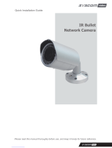
Description:
The CDIH226VIRF dome camera provides
high quality video with (1080p) 2.0 mega
pixel resolution. The
Remote Focus
capability allows you to optically zoom and
fine-focus the camera over the network,
eliminating the need to use two installers to
hand-focus the camera.
The IP66
weatherproof rating makes this bullet camera
suitable for outdoor applications such as gas
stations, retail parking lots and many others.
Costar Video’s IP cameras are compatible
with the iNEX user interface platform. The
iNEX user interface incorporates features
such as simplified user management,
advanced camera mapping and logical
camera grouping making it easier to monitor
and access each of your cameras. The iNEX
user interface also has the ability to integrate
both analog and IP camera technology on
the same platform allowing you to have a
diverse surveillance system. Costar Video’s
IP cameras are OnVIF supported. The
industry standard OnVIF protocol makes it
easy to integrate Costar branded IP cameras
with OnVIF compatible recorders.

Quick Installation Guide
1. Description
The Network Camera supports the network service for a sensor image with progressive scan, which
can be monitored on a real-time screen regardless of distances and locations. By using its dedicated
program, many users are able to have an access to the Network Camera at once or a single user can
monitor various network cameras at the same time. It also enables users to play, store and retrieve a
monitoring image by using a PC. All the settings and real-time monitoring screens are also provided
through an access to the web.
The Network Camera is fully featured for security surveillance and remote monitoring needs. It is
based on the DSP compression chip, and makes it available on the network as real-time, full frame
rate Motion JPEG and H.264 (or MPEG-4) video streams.
The alarm input and alarm output can be used to connect various third party devices, such as, door
sensors and alarm bells.
• Installation Steps
Follow these steps to install the network camera on your local network (LAN):
1. Check the package contents against the list below.
2. Connect the Network Camera. See page 3.
3. Set an IP address. See page 6.
4. Set the password. See page 8.
• Package Component
The system comes with the following components:
Check your package to make sure that you received the complete system, including all components
shown above.
2

Quick Installation Guide
• Contents in the installation CD
1. The Network Camera User’s Manual
2. The SmartManager User’s Manual
3. The NCTitanium User’s Manual
4. The SmartManager Installation software
5. The NCTitanium Installation software
Note: Check your package to make sure that you received the complete system, including all
components shown above.
2. Installation
For the operation of the Network Camera, it is necessary to connect a network cable for data
transmission, power connection from supplied power adapter. Depending on operation methods, it is
possible to connect an alarm cable additionally. For its fixation on different locations, please consult
with an installer.
2.1 Connection
Connection Description
NO
Connector Name
Description
1
Micro-SD Slot
Micro-SD memory slot
2
Service Monitor
Port
Service Monitor & OSD Controller Communication Port, Stereo Jack
3 Audio In & Out Port Audio Input and Output, Stereo Jack.
4 Alarm In & Out Port
Alarm Input and Output, 3pin terminal.
Pin1: Alarm In, Pin2: GND, Pin3: Alarm Out
5
Main Power
Main Power, 2pin terminal,
DC12V 470mA(4.0W) / AC24V 520mA(6.5W) with heater Off,
or AC24V 1.13A(25.5W) with heater On
Pin1: DC12V/AC24V, Pin2: GND/AC24V
6 RJ-45 Port
Ethernet, RJ-45 port compatible with 10/100Mbps having PoE
functionality.
3

Quick Installation Guide
Micro SD memory slot on the Board
Card Slot for Micro SD memory: Socket “J15”
• Connecting to the RJ-45
Connect a standard RJ-45 cable to the network port of the network camera. Generally a
cross-over cable is used for directly connection to PC, while a direct cable is used for connection
to a hub.
You can also use a router featuring PoE (Power over Ethernet) to supply power to the camera.
• Connecting Alarms
AI(Alarm In) :
You can use external devices to signal the network camera to react on events. Mechanical or
electrical switches can be wired to the AI (Alarm In) and G (Ground) connectors.
G(Ground) :
Connect the ground side of the alarm input and/or alarm output to the G (Ground) connector.
Alarm Out :
The network camera can activate external devices such as buzzers or lights. Connect the device
to the AO (Alarm Out) and G (Ground) connectors.
• Connecting the Power
Connect the power of DC12V or AC24V for the network camera. Connect the positive(+) pole to
the ‘+’ position and the negative(-) pole to the ‘-‘ position for the DC power.
Be careful not to reverse the polarity when you connect the power cable.
You can also use a router featuring PoE (Power over Ethernet) to supply power to the
camera.
The heater will operate properly only by the power source of AC 24V.
If using PoE, the heater will not operate at all.
If PoE and DC 12V are both applied, this camera will get supplied with power from PoE.
• Connecting Service Monitor Port
Service monitor output port (J7) is located on the board of the dome camera, and is used for an
easy OSD setup.
▶ ID & IP assignment
To make changes in the OSD menu, please use the OSD controller provided optionally with your
camera purchase. You can set Camera Title and IP Address.
4

Quick Installation Guide
1. Connect the OSD Controller to the Service Monitor port of the network camera.
2. Connect Service Monitor and the Video Output port of the OSD Controller.
3. Press the SET button to access main Menu.
4. Change Camera ID, and IP Address. You can change the Name or Title and IP address of the
camera. Using the ↑↓←→ buttons on the controller, you can change the parameters.
5. Select SAVE or CANCEL to exit the Main Menu.
Video Output is used for an easy zoom and focus control when installing lens. Video Output is
restricted to 704x480(576) resolution.
▶ Zoom & Focus Control
The camera enters Zoom and Focus control mode as soon as connecting OSD Controller to the
Service Monitor port.
-. Zoom Control: ↑(Zoom In), ↓(Zoom Out)
-. Focus Control: ←(Focus Near), →(Focus Far)
-. Smart Focus: Press and hold the SET button for 2 or more seconds. The camera readjusts
focus automatically.
Note: You can get the Optional OSD Controller from your installer.
Heater Kit Installation(Optional)
1. Place the heater element is slot “A”. Please ensure that the cables are facing upwards and the
heater is pointing towards the Dome.
2. Place the plug in the Connector “B” (J13) which is found on the controller board.
• Heater (IF Applicable)
Power Supply
AC24V
Power Consumption
20Watt
Heater On
at 41°F (5°C)
Heater Off
at 59°F (15°C)
Note: The Heater module does not come equipped with the camera; however can be purchased as
an option.
5

Quick Installation Guide
2.2 Network Connection and IP assignment
The Network Camera supports the operation through the network. When a camera is first connected
to the network it has no IP address. So, it is necessary to allocate an IP address to the device with the
“Smart Manager” utility on the CD. The factory default IP is “192.168.30.220”.
1. Connect the Network Camera / device to the network and power up.
2. Start SmartManager utility (All Programs>SmartManager>SmartManager), the main window will
be displayed, after a short while any network devices connected to the network will be displayed
in the list.
3. Select the camera on the list and click right button of the mouse. You can see the pop-up menu
as below.
4. Select Assign IP. You cam see a Assign IP window.
Enter the required IP address.
6

Quick Installation Guide
3. Operation
The Network Camera can be used with Windows operating system and browsers. The recommended
browsers are Internet Explorer, Safari, Firefox, Opera and Google Chrome with Windows.
3.1 Access from a browser
1. Start a browser (Internet Explorer).
2. Enter the IP address or host name of the Network Camera in the Location/Address field of your
b r o w s e r.
3. You can see a starting page. Click Live View or Setup to enter web page.
4. The network camera’s Live View page appears in your browser.
3.2. Access from the internet
Access from the internet once connected, the Network Camera is accessible on your local network
(LAN). To access the network camera from the Internet you must configure your broadband router to
allow incoming data traffic to the network camera. To do this, enable the NAT-traversal feature, which
will attempt to automatically configure the router to allow access to the network camera. This is
enabled from Setup > System > Network > NAT.
For more information, please see “3.5.5 System>Network>NAT” of User’s Manual.
7

Quick Installation Guide
3.3 Setting the admin password over a secure connection
To gain access to the product, the password for
the default administrator user must be set. This
is done in the “Admin Password” dialog, which is
displayed
when the network camera
is accessed
for the setup at the first time.
Enter your admin
name and password, set by the administrator.
Note: The default administrator username and
password is “admin”. If the password is lost, the
Network Camera must be reset
to the factory
default settings. See
“3.6 Resetting to the Factory
Default Settings”
.
3.4 Live View Page
The live view page comes in several screen
modes
: 1920x1080, 1280x1024, 1280x720,
7
04
x480(576), 640x480, 352x240(288),
and
320x240. Users are a
llowed to select
the most suitable one out of those modes.
Please, adjust the mode in accordance with
your PC specifications and monitoring
purposes.
1) General controls
Live View Page Search & Playback Page Setup Page Help Page
The video drop-down list allows you to select a customized or pre-programmed
video stream on the live view page. Stream profiles are configured under Setup > Basic
Configuration > Video & Image. . For more information, please see “3.5.1 Basic Configuration >
Video & Image” of User’s Manual.
The resolution drop-down list allows you to select the most suitable one
out of video resolutions to be displayed on live view page.
The protocol drop-down list allows you to select which combination of
protocols and methods to use depends on your viewing requirements, and on the properties of
your network.
2) Control toolbar
The live viewer toolbar is available in the web browser page only. It displays the following
buttons:
The Stop button stops the video stream being played. Pressing the key again toggles the
start and stop. The Start button connects to the network camera or start playing a
video stream.
8

Quick Installation Guide
The Pause button pause the video stream being played.
The Snapshot button takes a snapshot of the current image. The location where the
image is saved can be specified.
The digital zoom activates a zoom-in or zoom-out function for video image on the live
screen.
The Full Screen button causes the video image to fill the entire screen area. No other
windows will be visible. Press the 'Esc' button on the computer keyboard to cancel full
screen view.
The Manual Trigger button activates a pop-up window to manually start or stop the event.
The Remote Focus button enables users to adjust focus and zoom remotely via network.
The Smart Focus button readjusts focus automatically.
Use this scale to control the volume of the speakers.
Use this scale to control the volume of the microphone.
Use this scale to control the volume of the speakers and microphones.
3) Video and Audio Streams
The network camera provides several images and video stream formats. Your requirements and
the properties of your network will determine the type you use.
The Live View page in the network camera provides access to H.264, MPEG-4 and Motion JPEG
video streams, and to the list of available video streams. Other applications and clients can also
access these video streams/images directly, without going via the Live View page.
4) Focus and Zoom Control
You can control Zoom and Focus in the live screen. Press the button on the left top in the live
screen to activate the Zoom & Focus control panel.
9

Quick Installation Guide
• Adjusting Zoom:
Click “–“ button to zoom out and click “+” button to zoom in.
The focus is moved slightly after adjusting zoom; adjust the
focus again, as necessary.
• Adjusting Focus:
Click “–“ button for far focus and click “+” button to near focus.
Note: Click the button in the live screen to set the focus to the optimum position.
3.5 Network Camera Setup
This section describes how to configure the network camera, and is intended for product
Administrators, who have unrestricted access to all the Setup tools; and Operators, who have access
to the settings for Basic, Live View, Video & Image, Audio, Event, and System Configuration.
You can configure the network camera by clicking Setup in the top right-hand corner of the Live View
page. Click on this page to access the online help that explains the setup tools
When accessing the Network Camera for the first time,
the “Admin Password” dialog appears. Enter your admin
name and password, set by the administrator.
Note: If the password is lost, the Network Camera must
be reset to the factory default settings.
See “3.6 Resetting to the Factory Default Settings”.
3.6 Resetting to the factory default settings
To reset the Network Camera to the original factory settings, go to the Setup>System> Maintenance
web page (described in “3.5.5 System > Maintenance”) or use the Reset button (SW1) on the board
of the dome camera, as described below:
10

Quick Installation Guide
• Using the Reset Button
Follow the instructions below to reset the Network Camera to the factory default settings using
the Reset button.
1. Power off the Network Camera by disconnecting the power adapter.
2. Open the top cover of camera.
3. Press and hold the Reset button (SW1) on the board with your finger while reconnecting
the power.
4. Keep the Reset button (SW1) pressed during about 2 seconds.
5. Release the Reset button (SW1).
6. The network
camera resets to factory defaults and restarts after completing the factory reset.
The unit now has the default IP address 192.168.30.220.
7. Close the top cover of camera.
Caution: When performing a Factory Reset, you will lose any settings you have saved.
3.7 More Information
For more information, please see the Network Camera User’s Manual, which is available on the CD
included in this package.
11

Quick Installation Guide
12

Quick Installation Guide
Full-HD
VP DOME NETWORK CAMERA
Printed in Korea
13
/