1
IMPORTANT:
Go to www.extron.com for the complete
user guide, installation instructions, and
specifications before connecting the
product to the power source.
SSP 200 • Setup Guide
The Extron SSP 200 is a high-performance surround sound processor that automatically decodes Dolby
®
, DTS
®
, and PCM
formats from digital input sources to discrete audio outputs. Providing up to ten built-in balanced analog outputs, the SSP200
provides the exibility needed for pro A/V applications in corporate, commercial, and education environments. It supports
the latest immersive formats of Dolby Atmos and DTS:X plus legacy Dolby and DTS formats. An upmix function synthesizes
exceptional multichannel audio from stereo content. The SSP 200 features an HDMI input with loop through, coaxial and optical
digital inputs, and an analog stereo input. It is designed for integration into pro A/V installations, featuring a compact, half-rack
metal enclosure, RS-232 serial and LAN control, and balanced line level outputs.
This guide provides instructions for an experienced user to set up and congure the SSP 200. It covers how to connect
other devices and perform basic operations using rear panel connections and the front panel controls. For full operation and
conguration through Extron Product Configuration Software (PCS), internal web pages, and Simple Instruction Set (SIS™)
commands, see the SSP 200 User Guide.
NOTE: For information while using PCS, see the SSP 200 PCS Help File.
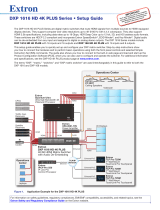
Rear Panel Connectors
50-60 Hz
100-240V
--A MAX
1 THRU
OUTS
DMP EXP
INPUTS
SSP 200
2
5
LR
34
1(LF) 2(RF) 3(C) 4(SUB) 5(LS) 6(RS)789 10(MIX)
RS-232
Tx Rx G
LAN
RESET
e
SSP 200
CONFIG
PCM
2-CH
ATMOS
HDCP
EXP
SURROUND SOUND PROCESSOR
SOURCE INPUT VOLUME
1 2 3 4 5
AAA
AAA CCC
BBB CCC
BBB
H
H
Figure 1. Rear Panel Connectors
A
AC power connector
B
Audio inputs
C
DMP expansion port
D
RS-232 port
E
LAN port
F
Reset button
G
Status light
H
Analog outputs
The SSP 200 (
A
) uses an IEC power cable to connect to a 100-240 VAC, 50-60 Hz, power source.
The SSP 200 (
B
) accepts one HDMI input with embedded audio, three digital inputs, and one analog input. In addition, there is
an HDMI loop out (through) connector.
• Input 1 accepts digital signals through an HDMI cable, supporting HDMI version 2.0 with HDCP version 2.3 compliance.
• Input 2 accepts a 75 ohm unbalanced digital coaxial S/PDIF input.
• Inputs 3 and 4 accept digital signals through S/PDIF optical (TOSLINK
®
) cables.
• Input 5 accepts a balanced or unbalanced, stereo or mono, analog input through a 6-pole captive screw connector.
Connect an EXP-enabled device to the DMP expansion port (
C
) for a digital audio connection using Extron proprietary protocol.
Use the included one-foot long shielded CAT6 cable to connect the SSP 200 to a Primary EXP-enabled device (see the SSP 200
User Guide for EXP bus operation details).
The ten outputs (
H
) are balanced or unbalanced, line level, analog signals made available through captive screw connectors
providing outputs for the following surround sound channels.
Number Abbreviation Channel Description Number Abbreviation Channel Description
1
LF Left front 6 RS Right surround
2 RF Right front 7 See note below
3 C Center 8 See note below
4 SUB Subwoofer 9 See note below
5 LS Left surround 10 See note below
NOTE: Numbers 7 through 10 are configurable as back, height, or downmix channels using PCS.
By default, the SSP 200 is set to 7.1 with downmix enabled with all ten analog outputs enabled. Outputs in this conguration are
7 – Left Back, 8 – Right Back, 9 – Downmix Left, and 10 – Downmix Right.
1