Owner’s Manual
PMC
16
Personal Monitor Controller

These symbols are internationally accepted symbols that warn of potential
hazards with electrical products. The lightning flash means that there are
dangerous voltages present within the unit. The exclamation point indi-
cates that it is necessary for the user to refer to the owner’s manual.
These symbols warn that there are no user serviceable parts inside the
unit. Do not open the unit. Do not attempt to service the unit yourself.
Refer all servicing to qualified personnel. Opening the chassis for any
reason will void the manufacturer’s warranty. Do no get the unit wet. If
liquid is spilled on the unit, shut it off immediately and take it to a dealer
for service.
Disconnect the unit during storms to prevent damage.
If you want to dispose this product, do not mix it with general household waste. There is a
separate collection system for used electronic products in accordance with legislation that
requires proper treatment, recovery and recycling.
Private household in the 25 member states of the EU, in Switzerland and Norway may return their used
electronic products free of charge to designated collection facilities or to a retailer (if you purchase a similar
new one).
For Countries not mentioned above, please contact your local authorities for a correct method of disposal.
By doing so you will ensure that your disposed product undergoes the necessary treatment, recovery and
recycling and thus prevent potential negative effects on the environment and human health.
ELECTROMAGNETIC COMPATIBILITY
This device complies with part 15 of the FCC Rules and
the Product Specifications noted on the Declaration
of Conformity. Operation is subject to the following
two conditions:
• this device may not cause harmful
interference, and
• this device must accept any interference received,
including interference that may cause undesired
operation.
Operation of this unit within significant
electromagnetic fields should be avoided.
• use only shielded interconnecting cables.

DECLARATION OF CONFORMITY
Manufacturer’s Name: dbx
Manufacturer’s Address: 8760 S. Sandy Parkway
Sandy, Utah 84070, USA
declares that the product:
Product name: dbx PMC16
Product option: all (requires Class II power adapter that
conforms to the requirements of EN60065,
EN60742, or equivalent.)
conforms to the following Product Specifications:
Safety: IEC 60065 -01+Amd 1
EMC: EN 55022:2006
EN 55024:1998
FCC Part 15
Supplementary Information:
The product herewith complies with the requirements of the:
Low Voltage Directive 2006/95/EC
EMC Directive 2004/108/EC.
RoHS Directive 2002/95/EC
WEEE Directive 2002/96/EC
EC Regulation 278/2009
With regard to Directive 2005/32/EC and EC Regulation
1275/2008 of 17 December 2008, this product is designed,
produced, and classified as Professional Audio Equipment and
thus is exempt from this Directive.
Roger Johnsen
Director, Engineering
Signal Processing
8760 S. Sandy Parkway
Sandy, Utah 84070, USA
Date: August 29, 2012
European Contact: Your local dbx Sales and Service Office or
Harman Signal Processing
8760 South Sandy Parkway
Sandy, Utah
84070 USA
Ph: (801) 566-8800
Fax: (801) 568-7583
Warning
For your protection, read the following:
Important Safety Instructions
1. Read these instructions.
2. Keep these instructions.
3. Heed all warnings.
4. Do not use this apparatus near water.
5. Clean only with dry cloth.
6. Do not block any ventilation openings. Install in accor-
dance with the manufacturer’s instructions.
7. Do not install near any heat sources such as radiators,
heat registers, stoves, or other apparatus (including
amplifiers) that produce heat.
8. Protect the power cord from being walked on or
pinched particularly at plugs, convenience receptacles,
and the point where they exit from the apparatus.
9. Unplug this apparatus during lightning storms or when
unused for long periods of time.
10. No user serviceable parts inside. Refer all servicing to
qualified service personnel. Servicing is required when
the apparatus has been damaged in any way, such as
power-supply cord or plug is damaged, liquid has been
spilled or objects have fallen into the apparatus, the
apparatus has been exposed to rain or moisture, does
not operate normally, or has been dropped.
11. WARNING: To reduce the risk of fire or electric
shock, do not expose this apparatus to rain or mois-
ture.
12. Refer to labels on the unit, including bottom cover, or
other markings and pertinent information.

Support/Service contact
If you require technical support, contact dbx Technical Support. Be prepared to accurately describe
the problem. Know the serial number of your device–this is printed on a sticker attached to the
chassis. If you have not already taken the time to fill out your warranty registration card and send it
in, please do so now. You may also register online at www.dbxpro.com.
Before you return a product to the factory for service, we recommend you refer to the manual. Make
sure you have correctly followed installation steps and operation procedures. For further technical
assistance or service, please contact our Technical Support Department at (801) 568-7660 or visit
www.dbxpro.com. If you need to return a product to the factory for service, YOU MUST FIRST
CONTACT TECHNICAL SUPPORT TO OBTAIN A RETURN AUTHORIZATION NUMBER.
NO RETURNED PRODUCTS WILL BE ACCEPTED AT THE FACTORY WITHOUT A RETURN AUTHORIZATION
NUMBER.
Please refer to the Warranty information on the following page, which extends to the first end-user.
After expiration of the warranty, a reasonable charge will be made for parts, labor, and packing if you
choose to use the factory service facility. In all cases, you are responsible for transportation charges
to the factory. dbx will pay return shipping if the unit is still under warranty.
Use the original packing material if it is available. Mark the package with the name of the shipper
and with these words in red: DELICATE INSTRUMENT, FRAGILE! Insure the package properly. Ship
prepaid, NOT COLLECT. DO NOT SHIP PARCEL POST.

Warranty
1. The warranty registration card that accompanies this product must be mailed within 30 days after
purchase date to validate this warranty. You can also register online at www.dbxpro.com. Proof-of-
purchase is considered to be the responsibility of the consumer. A copy of the original purchase
receipt must be provided for any warranty service.
2. dbx warrants this product, when purchased new from an authorized U.S. dbx dealer and used solely
within the U.S., to be free from defects in materials and workmanship under normal use and service.
This warranty is valid to the original purchaser only and is non-transferable.
3. dbx liability under this warranty is limited to repairing or, at our discretion, replacing defective
materials that show evidence of defect, provided the product is returned to dbx WITH RETURN
AUTHORIZATION from the factory, where all parts and labor will be covered up to a period of two
years. A Return Authorization number must first be obtained from dbx. The company shall not be
liable for any consequential damage as a result of the product’s use in any circuit or assembly.
4. dbx reserves the right to make changes in design or make additions to or improvements upon this
product without incurring any obligation to install the same additions or improvements on products
previously manufactured.
5. The foregoing is in lieu of all other warranties, expressed or implied, and dbx neither assumes nor
authorizes any person to assume on its behalf any obligation or liability in connection with the sale
of this product. In no event shall dbx or its dealers be liable for special or consequential damages or
from any delay in the performance of this warranty due to causes beyond their control.

PMC
16
Owner’s Manual
toc
table of contentS
INTRODUCTION ............................................................. 1
PHILOSOPHY ................................................................ 2
FEATURES ..................................................................... 4
PACKAGE CONTENTS ...................................................... 5
QUICK START ................................................................ 6
PANEL DESCRIPTIONS .................................................... 8
Top Panel ................................................................ 8
Rear/Side Panels .....................................................11
MIC STAND MOUNTING INSTRUCTIONS ........................... 13
MAKING CONNECTIONS–CABLING .................................. 14
Power ....................................................................14
Analog Outputs .......................................................14
Headphone Outputs .................................................14
BLU link.................................................................15
APPLICATIONS ............................................................ 16
Personal Monitoring w/dbx TR1616 ............................16
Personal Monitoring w/BSS Audio Soundweb London
System ..................................................................18
16 x 16 Digital Snake w/Personal Monitoring ...............20
32 x 32 Digital Snake w/Personal Monitoring ...............22
THE LCD DISPLAY ........................................................ 24
Introduction To The Meters Page ...............................24
SETUP MODE–THE SETUP WIZARD & SETUP MENUS .......... 26
Setup Mode Introduction ..........................................26
The Setup Wizard ....................................................27
Setup Wizard Options ...............................................28
The Setup Menus .....................................................30
Setup Menu Options ................................................31
LIVE MODE–THE PMC16 MONITOR MIXER ....................... 36
Live Mode Introduction ............................................36
Using Multi-Select ...................................................39
Using Groups ..........................................................40
Adjusting Channel Levels ..........................................41
Adjusting Channel Pans ............................................42
Adjusting Effect Sends .............................................43
Using The Solo Function ...........................................44
Using The Mute Function ..........................................45
Using The Clear Function ..........................................46
Using The Global Trim Function .................................47
THE TOP PANEL KNOBS ................................................ 48
REVERB ..................................................................48
LOW ......................................................................48
HIGH .....................................................................48
MASTER .................................................................48
PRESETS ..................................................................... 49
Storing & Recalling Presets .......................................50
FACTORY RESET ........................................................... 52
FIRMWARE UPDATES .................................................... 53
BLOCK DIAGRAM ......................................................... 54
DIMENSIONS ............................................................... 56
SPECIFICATIONS .......................................................... 57

PMC
16
Owner’s Manual
1
introduction
Thank you for choosing the dbx
©
PMC16 personal monitor controller. The PMC16 is a digital
remote control providing a cost effective and powerful personal monitoring solution.
Whether using headphones, in-ear monitors, powered monitors, or traditional wedge
monitors, the PMC16 allows performing musicians to control their own personalized stage
monitor mix with ease.
Using BLU link, the PMC16 is capable of receiving up to 16 channels of high-end digital
audio via CAT5e cable. The PMC16 comprises a 16 channel monitor mixer section with full
control of levels, panning, effect send levels, muting, and soloing.
The PMC16’s output processing section includes: stereo width control, wedge monitor
compensation, high and low master EQ, master level control, and dbx limiting. Built-in
Lexicon
©
courtesy reverb rounds out the all-star processing power of the PMC16.
With a Setup Wizard for ease of configuration, full 16 channel monitor mixer level
metering, channel grouping, 16 preset locations for future recall of configurations and
mixes, and an intuitive yet powerful user interface, PMC16 gives you the power to dial in
YOUR mix exactly as YOU want it, in real time.

PMC
16
Owner’s Manual
2
philoSophy
The PMC16 is a digital remote control consisting of a monitor mixer, a reverb effect
processor, and a global processing and output section. This creates an audio chain akin
to a traditional live sound monitoring system and puts it in the hands of the on-stage
musician, allowing each on-stage musician to tailor their own personalized mix and allow
the system engineer to focus on the front of house mix.
The PMC16 has two modes of operation: Setup Mode and Live Mode. Setup Mode refers to
the Setup Wizard and Setup Menus which are visible when the WIZARD button is pressed.
This mode is used by the system engineer to initially create the “configuration” and set
global options. Live Mode is the mode which refers to normal operation and consists of all
parameters pertaining to the “mix”. When the on-stage musician is editing their mix, they
are doing so in Live Mode. Live Mode consists of four pages, they are: the Meters page,
the Levels page, the Pan page, and the Effects page. Using these four pages allows each
musician to create their own unique mix by adjusting each instrument’s gain, placement
in the stereo field, and front to back spacial placement, using reverb. Channel muting and
soloing are available to help each musician focus on channels which require attention or
channels which should be eliminated from the mix.
The PMC16’s Setup Wizard assists the system engineer during setup and allows for quick,
easy configuration of the PMC16. The PMC16’s Live Mode of operation was designed to
provide a fast, intuitive navigational experience, so musicians new to the PMC16 can start
using the system immediately.

PMC
16
Owner’s Manual
3
The PMC16 receives audio via the BLU link audio over Ethernet protocol. When assigning
BLU link audio channels to the PMC16, each PMC16 input channel can be assigned any
available BLU link channel on the network. This allows the system engineer to send any
BLU link audio channels on the network to any PMC16, so each musician receives the
channels of audio they require to create their mix.
The output processing in the PMC16 was designed to provide the best listening experience
possible. Stereo width control allows the system engineer to optimize the outputs for
wedge monitors, headphones, or in-ear monitoring. Stereo width is completely variable,
allowing for normal stereo operation, full mono collapse of the stereo image for mono
wedge monitors, hyper-stereo for use with headphones or stereo in-ear monitors, or
anything in between. Lexicon® courtesy reverb is provided to help the mix really come
to life!
The PMC16 was designed to provide all the outputs necessary for almost any application.
Two XLR outputs are available for connecting to amplifiers and powered wedge monitors.
Two 1/4” outputs allow for connection to any balanced or unbalanced line level device,
such as in-ear transmitters or recording devices. The 1/4” and 1/8” headphone outputs
ensure you won’t be stuck with headphones that aren’t compatible.
The on-board USB, DSC, and Ethernet ports allow the PMC16 to be built upon and exciting
new features to be added in the future, ensuring the PMC16 is prepared for what lies
ahead.

PMC
16
Owner’s Manual
4
featureS
• 16 Channel Monitor Mixer With Level, Pan, Mute, Solo, & Reverb Send Control
• 16 Preset Locations For Mix & Configuration Recall
• LCD Display With 16 Channel Metering
• Lexicon
©
Courtesy Reverb
• dbx PeakStopPlus™ Limiting
• Global High & Low EQ
• Global Master Level Control
• Global Stereo Width Control
• BLU link High Bandwidth, Fault Tolerant Digital Audio Bus
• XLR & 1/4” Stereo Or Mono Outputs
• 1/8” & 1/4” Headphone Outputs
• Setup Wizard
• Supports 48 kHz & 96 kHz Sampling Rates
• Channel Linking, Grouping, & Multi-Select Capabilities
• Supports Up To 60 PMC16s On A Single BLU link Ring
• Built-In Sturdy Mic Stand Mount

PMC
16
Owner’s Manual
5
package contentS
The PMC16 was packaged with extreme care. Please take a moment to ensure the items
listed below were received and that no damage to contents has occurred.
• PMC16 Personal Monitor Controller
• Power Supply
• Manual

PMC
16
Owner’s Manual
6
Quick Start
Configuration
1. Mount the PMC16 to a mic stand, if desired.
2. If connecting to a wedge monitor, turn off the power to the amplifier or powered
monitor.
3. Ensure the PMC16’s <MASTER> level control is turned all the way down (fully
counterclockwise).
4. Using the appropriate output connector, connect the PMC16 to the desired
monitoring device (i.e. headphones, in-ear monitor transmitter, amplifier, or
powered wedge monitor).
5. Connect the BLU link output of the sending BLU link device to the PMC16’s BLU
LINK IN port.
6. Connect the BLU LINK OUT port of the PMC16 to the next BLU link device in the
ring.
7. Connect the included power supply to the PMC16’s power input jack and the other
end to an available AC outlet.
8. Run the PMC16’s Setup Wizard by pressing the <WIZARD> button. Ensure “Setup”
Wizard” is selected on the display then press the <DATA> encoder to begin the
Wizard. Select the “RUN ALL SETUP ITEMS” option and press the <DATA> encoder.
9. Follow the on-screen instructions and select the appropriate options for your
system configuration.

PMC
16
Owner’s Manual
7
10. When prompted, store the configuration to a preset. Follow the on-screen
instructions to name the preset and select a location in which to store the preset.
11. Once the Wizard is complete, press the <PRESET> button to return to Live mode.
12. Apply power to your amplifier or powered monitor.
13. Send signal to the PMC16 (signal presence can be verified on the PMC16’s LCD
display which displays all input level meters on the Meters page).
14. Slowly raise the PMC16’s <MASTER> level control to the initial desired listening
level.
Operation
15. Use the mute and solo functions to help create your mix, bringing channels into
focus using SOLO or eliminating channels from the mix using MUTE.
16. Adjust channel levels by using the <LEVELS> button, <CHANNEL SELECT> buttons,
and the <DATA> encoder.
17. Adjust channel pans by using the <PAN> button, <CHANNEL SELECT> buttons, and
the <DATA> encoder.
18. Turn the <REVERB> control to adjust how much overall reverb you would like in
the mix. If you would like to further adjust each channel’s reverb effect send level,
press the <EFFECTS> button and use the <CHANNEL SELECT> buttons for selecting
channels. Turn the <DATA> encoder to edit the selected effect send level(s).
19. If desired, save the mix to a preset by pressing the <PRESET> button and following
the on-screen instructions.

PMC
16
Owner’s Manual
8
panel deScriptionS
Top Panel
1 2 3 4 5 6 7 8
9
10
11
12
1. LCD Display
This LCD display shows input metering, menus, pages, and parameters and is used
during configuration and operation.
2. DATA Encoder
The DATA encoder is used for navigating menus, on-screen option selection, and
parameter editing.

PMC
16
Owner’s Manual
9
3. BACK Button
This button navigates back one page when navigating menus. This button also
navigates back to the Meters page when pressed multiple times (depending upon
how deep you are nested within a menu).
4. Function Buttons
• WIZARD Button–Pressing this button allows access to the PMC16 Setup Wizard
and Setup Menus for initially configuring the PMC16.
• GROUP Button–Toggles the Group function on and off.
• PRESET Button–Pressing this button allows for the storing or recalling of a
preset.
• LEVEL Button–Enters the Level page for adjusting each channel’s level.
• PAN Button–Enters the Pan page for adjusting each channel’s pan setting.
• EFFECTS Button–Enters the Effects page for adjusting each channel’s effect
send level.
5. REVERB Knob
This control allows for quick adjustment of the reverb’s return level, which adjusts
the overall reverb level.
6. LOW Knob
This control allows for quick adjustment of the low band shelving filter. This control
affects all outputs and is used to control the low-end frequencies of the mix.

PMC
16
Owner’s Manual
10
7. HIGH Knob
This control allows for quick adjustment of the high band shelving filter. This
control affects all outputs and is used to control the high-end frequencies of the
mix.
8. MASTER Knob
This control allows for quick adjustment of the master output level. This control
affects all outputs and is pre-limiter.
9. Master Level Meter
This 4-segment LED meter displays the output signal level. The four LEDs represent
-30 dBu, 0 dBu, +10 dBu, and +17 dBu (3 dB below the clip point).
10. Channel Monitor Buttons
• CLEAR Button–Used to quickly clear all muted or soloed channels.
• SOLO Button–Used to solo channels or channel groups.
• MUTE Button–Used to mute channels or channel groups.
11. Scribble Strip
Use a non-permanent marker on this strip to label each channel.
12. Channel Select Buttons (1-16)
Allows for the selection of channels or channel groups for editing levels, pans,
effect sends, mutes, or solos. Dual LEDs on each button indicate channel selection
(top LED=green), solo state (bottom LED=amber), and mute state (bottom
LED=red).

PMC
16
Owner’s Manual
11
Rear/Side Panels
2
1
3 54 6 7 8
9
10
1. Power Supply Input Jack
Used for providing power to the PMC16. Connect only the included power supply to
this jack.
2. Power Cord Clip
This clip holds the power cord, preventing the power plug from accidental removal.
3. BLU LINK IN/OUT Ports
These BLU link ports allow you to connect to any BLU link compatible device and
allow for the daisy chaining of multiple PMC16 remotes.
4. ETHERNET Port
This port allows for future expansion of the PMC16’s feature set.

PMC
16
Owner’s Manual
12
5. DSC Input Port
This port allows for future expansion of the PMC16’s feature set.
6. USB Port
This Mini USB port is used for updating the PMC16’s firmware.
7. 1/4” Outputs
Connect these balanced outputs to any balanced or unbalanced line level device,
such as an in-ear transmitter or recording device.
8. XLR Outputs
Connect these balanced outputs to an amplifier or powered wedge monitor.
9. 1/4” Headphone Output
Connect this output to headphones which have a 1/4” headphone plug.
10. 1/8” Headphone Output
Connect this output to headphones which have a 1/8” mini headphone plug.

PMC
16
Owner’s Manual
13
Mic Stand Mounting inStructionS
To install the PMC16 to a mic stand:
1. Align the mounting hole on the bottom of the PMC16’s chassis to the threads
on the top of the mic stand.
2. Carefully turn the PMC16 clockwise to begin threading the PMC16 to the mic
stand, ensuring the threads are properly aligned. Be careful not to cross-
thread the threads or overtighten.
Note: The threaded mounting hole in the bottom of the PMC16 chassis is compatible
with 5/8” (1.6 cm) mic stand mounts.

PMC
16
Owner’s Manual
14
Making connectionS–cabling
Power
Use only the included power supply for supplying power to the PMC16. A power supply
with the incorrect specifications may cause damage to the device. See “Specifications” for
further information on this power supply.
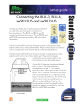
Analog Outputs
The 1/4” and XLR analog outputs provide
balanced audio connections. If connecting
to unbalanced equipment, use the 1/4”
outputs. The wiring conventions of these
connectors are shown to the right.
1/4” XLR
Tip
Hot
Pin 1
Ground
Ring
Cold
Pin 2
Hot
Sleeve
Ground
Pin 3
Cold
Note:
The 1/4” and XLR output jacks can be used simultaneously as long as the
combined parallel load equals 400 Ω or greater.
Headphone Outputs
The 1/8” and 1/4” headphone outputs each have an impedance of 50 Ω. It is recommended
that headphones connected to these jacks have an impedance rating of 50 Ω or greater.
Note: The 1/8” and 1/4” headphone jacks are paralleled. Both connections can be used
simultaneously as long as the combined parallel load equals 50 Ω or greater.
Page is loading ...
Page is loading ...
Page is loading ...
Page is loading ...
Page is loading ...
Page is loading ...
Page is loading ...
Page is loading ...
Page is loading ...
Page is loading ...
Page is loading ...
Page is loading ...
Page is loading ...
Page is loading ...
Page is loading ...
Page is loading ...
Page is loading ...
Page is loading ...
Page is loading ...
Page is loading ...
Page is loading ...
Page is loading ...
Page is loading ...
Page is loading ...
Page is loading ...
Page is loading ...
Page is loading ...
Page is loading ...
Page is loading ...
Page is loading ...
Page is loading ...
Page is loading ...
Page is loading ...
Page is loading ...
Page is loading ...
Page is loading ...
Page is loading ...
Page is loading ...
Page is loading ...
Page is loading ...
Page is loading ...
Page is loading ...
Page is loading ...
Page is loading ...
/